• ALÂMINAPODE SER VIOLENTAMENTEREPELIDADE MATERIALQUENÃO CONSIGACORTAR -Aprojecção da lâmina pode
provocaraamputaçãodebraçosoupernas.Mantenhaaspessoaseanimaisaumadistânciade10metrosemtodasasdirecções.Se
alâminaentraremcontactocomobjectosestranhosduranteofuncionamento,desligueomotoreaguardeatéquealâminapare.Em
seguida,verifiquesealâminaestádanificada.Deitesempreforaalâminaseestiverdeformadaourachada.
• ALÂMINAPROJECTAVIOLENTAMENTEOBJECTOS - Pode ficar cego ou ferido. Use protecções para os olhos, face e pernas.Antes
deutilizaralâmina,retiresempretodososobjectosestranhosdaáreadetrabalho.Mantenhaaspessoaseanimaisaumadistânciade
10metrosemtodasasdirecções.
• INSPECCIONEOAPARADOR DE RELVAEACESSÓRIOSANTES DE O UTILIZAR - Nunca utilize o equipamento se os res-pectivos
componentesnãoestiveremdevidamentemontados.
• ALÂMINAPÁRADEPOIS DAVÁLVULADEBORBOLETASERSOLTA-Umalâminaemrotaçãoporinérciapodecortarooperadorou
ostranseuntes.Antes de efectuar qualquer reparação na lâmina, desligue o motor e certifique-se de que a lâmina está parada.
• ZONADE PERIGO COM DIÂMETRO DE 20 metros - Os transeuntes podem ficar cegos ou feridos. Mantenha as pessoas e animais
aumadistânciade10metrosemtodasasdirecções.
3. INSTRUÇÕESDE MONTAGEM
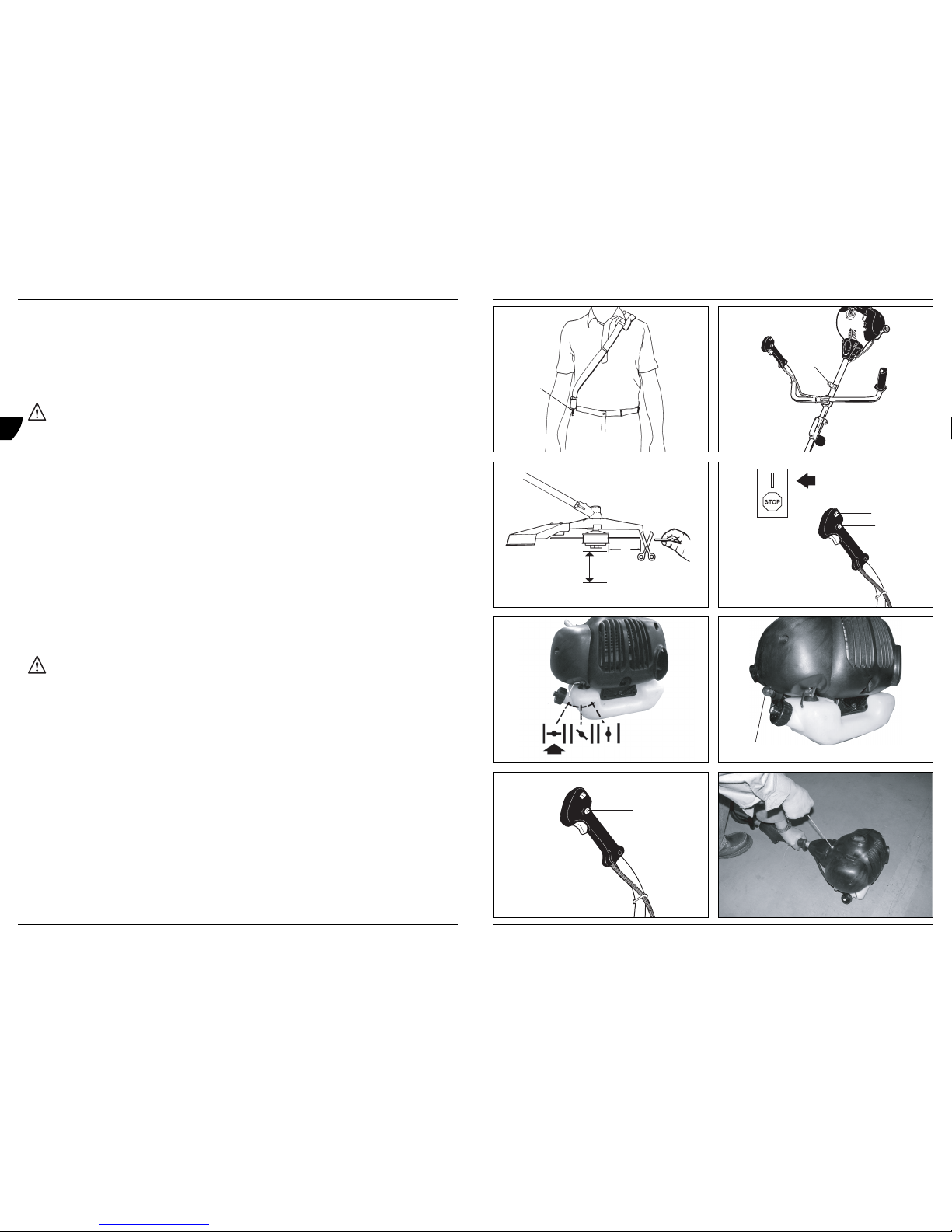
Montagemdapega“Bike”
Fig. 2A + 2B
• Parainstalarapeganoequipamento,sãonecessáriososseguintescomponentesdokitdeutilizador:Pega“Guiadordebicicleta”(A),
suportedefixação(B),grampo(C)eparafusos(D).
• Coloqueosuportedefixação(B)noveioaumadistânciade10a12cmdaextremidadedapega,monteogrampo(C)eaperteos2
parafusos(D).
• ColoqueapegaemformadeU(A)nosuportedefixação,monteooutrogrampo(C)eaperteosoutros2parafusos(D).
• Coloqueofreio(E)incluídonokitdeutilizadorconformeindicado.
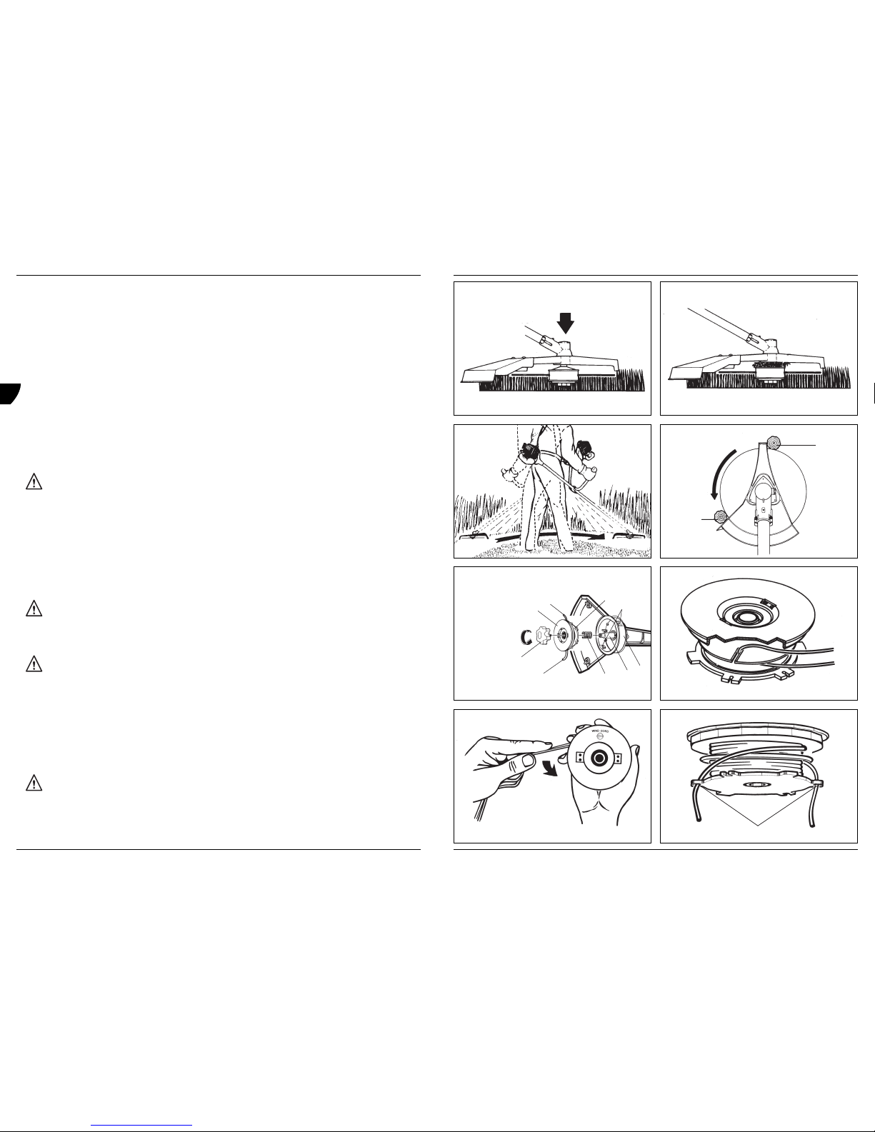
Instalaroequipamento
Fig. 3A + 3B
Para evitar lesões pessoais graves, desligue o equipamento antes de remover ou instalar o acessório.
Nota:parafacilitarainstalaçãoouremoçãodoacessório,coloqueoequipamentonochãoounumabancada.
• Rodeobotão(A)nosentidoopostodosponteirosdorelógioparadesapertaroacessório.
• Mantendooacessório(B)firmementefixo,empurre-odirectamenteparaoconectordemudançarápida(C)atéobotãodelibertação(D)
aparecernoorifícioprincipal(E)doconectordemudançarápida.
O botão de libertação deve estar colocado no orifício principal e o botão devidamente fixo antes de utilizar o equipamento.
• Rodeobotão(A)nosentidodosponteirosparaapertá-lo.
Todos os acessórios foram concebidos para serem utilizados no orifício principal, excepto indicação em contrário no manual do utilizador
relativosaacessóriosespecíficos.Seforutilizadooorifícioincorrecto,issopodedarorigemadanosnoequipamento.
Montagemdaprotecçãodalâmina
Fig. 4A + 4B
• Retireotampãodaengrenagem(A)doveiodacaixadeengrenagemroscada.
• Coloqueaprotecçãodacaixadeengrenagemealinheosorifíciosdemontagem.Insiraosparafusos(B)talcomoindicadonaimageme
aperte-oscomcuidado.
• Coloquedenovootampãodaengrenagem(A).Certifique-sedequeoseparadordotampão(C)estácolocado,poiscasocontrário
otampãoirároçarnacaixadeengrenagem.
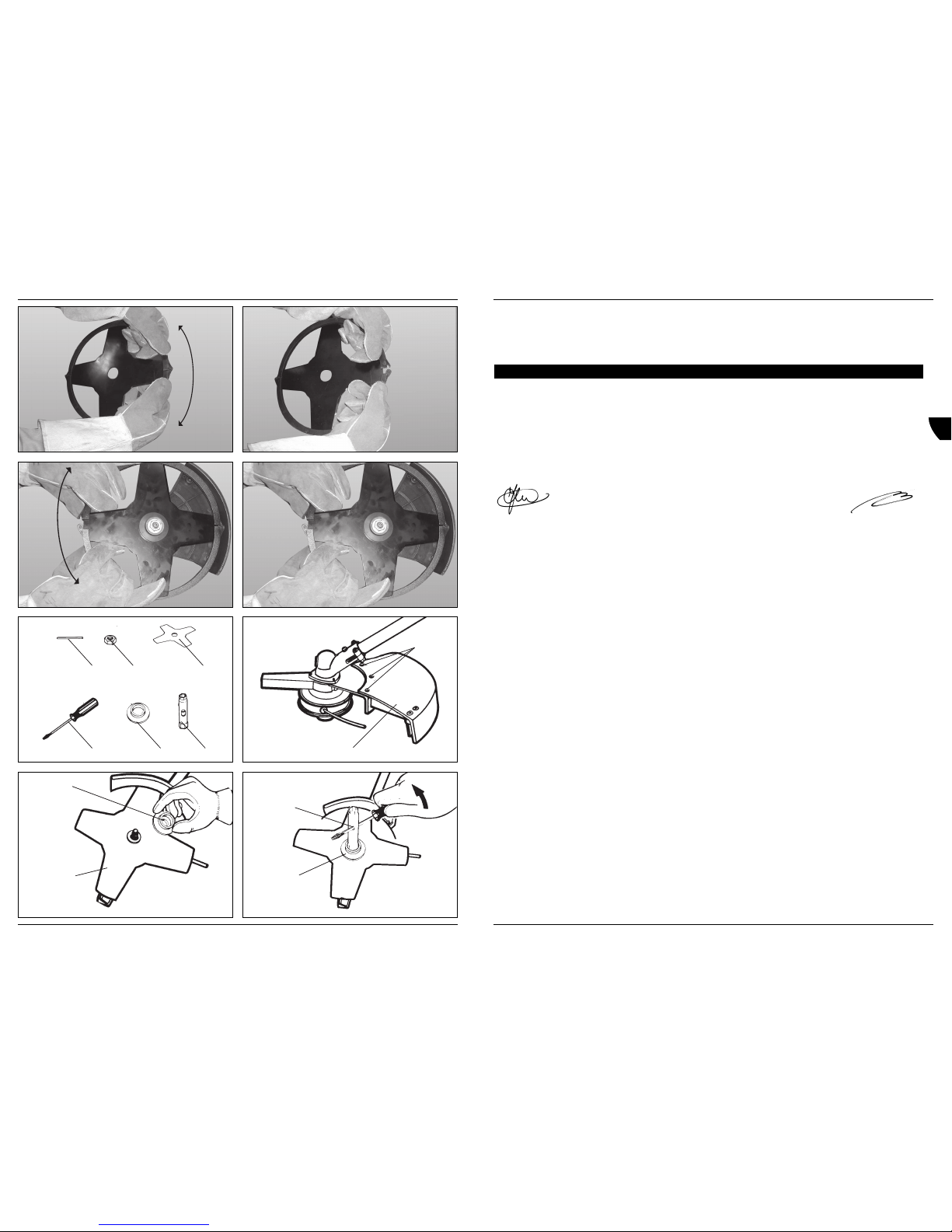
Montagemdacabeçadecorte
Fig. 5A + 5C
• Monteotampãodeengrenagem(A),certificando-sedequeoseparadordotampão(B)estácolocado.
• Insiraopinodefixação(C)eenrosqueacabeçadecortenoveio.Aperte a cabeça de corte à mão/
Montagemdaprotecçãocontrafragmentos
Fig. 6
Vireo equipamento ao contrário e monte a protecção contra fragmentos (A) conforme indicado.
A protecção deve ser instalada de modo a distribuir correctamente a linha de corte e a proteger o operador.
Ferm 63
GB
D
NL
F
E
P
PETROLGRASS TRIMMER32CC
The numbers in the following text correspond with the figures on page 2-10.
Please read and make sure that you understand this manual before operation. Keep it in a safe place for future reference. It
contains specifications and information for operation, starting, stopping, maintenance, storage, and assembly specific to this
product.
Please read and make sure that you understand the safety instructions before operation. Keep it in a safe place for future
reference. It explains possible hazards involved with the use of this product and which measures you should take to make using
this product safer.
Introduction
Thisproductwasdesignedandmanufacturedtoprovidelonglifeandon-the-jobdependability.Pleasereadandmakesurethatyou
understandthismanual.Youwill find it easy to use and full of helpful operating tips and safety messages. Specifications, descriptions and
illustrativematerialinthisliteratureareasaccurateasknownatthetimeofpublication,butaresubjecttochangewithoutnotice.Illustrations
mayincludeoptionalequipmentandaccessories,andmaynotincludeallstandardequipment.
Contents
1. Machinedata
2. Safety
3. Assemblyinstructions
4. Operatinginstructions
5. Maintenance
1.MACHINE DATA
Technicalspecifications
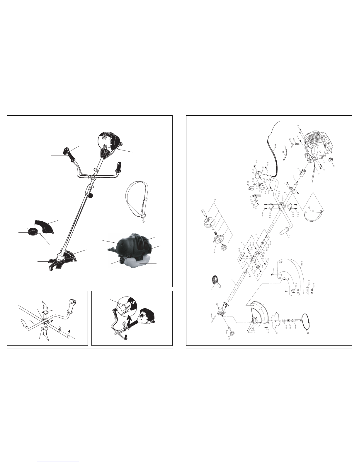
Generalidentification
Fig. 1
1. Stringhead
2. Cutterline
3. Debrisshield
4. Blade
5. Bladeguard
6. Driveshaftassembly
7. “Bike”handle
8. Throttletrigger
9. ON/OFFSwitch
10. Safetytrigger
11. Lockknob
12. Chokelever
13. Starterropehousing
14. Fueltank
15. Airfiltercover
Enginetype Air-cooled,2-cycle,chromecylinder
Displacement 32cm3
Dryweight 7.0kg
Fuelcapacity 710cm3
Bumphead Twin line bump feed
Blade 4teeth
Driveshaftlength 66+66cm
Cuttingwidth
Twin line head 43 cm
Blade 23cm
Handle „Bike“handle
Ignition Electronic
Drive Centrifugalclutch
Soundpowerlevel 110dB(A)
Vibrationat high speed 9.46 m/s2
Performance 0.75kW
Recommendedmaximumrotationalfrequencyofthespindle
Twin line 8500 min-1
Blade 11000min-1
Idlespeed 3050±350min-1
Fuelconsumption 620g/kWh
10 Ferm
GB
D
NL
F
E
P