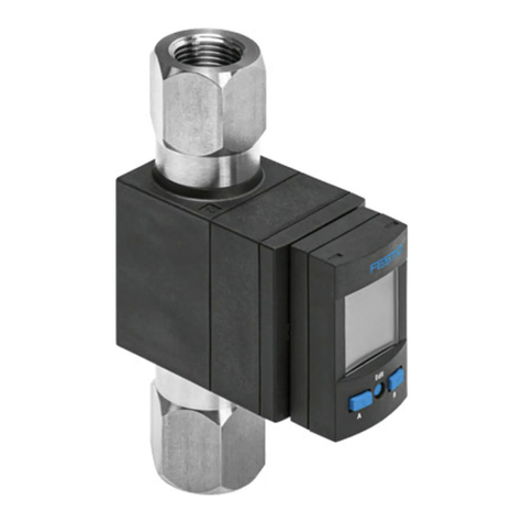
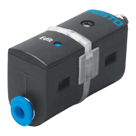
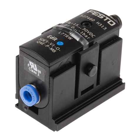
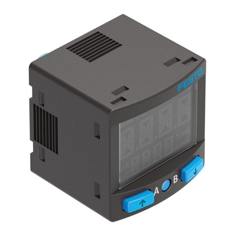
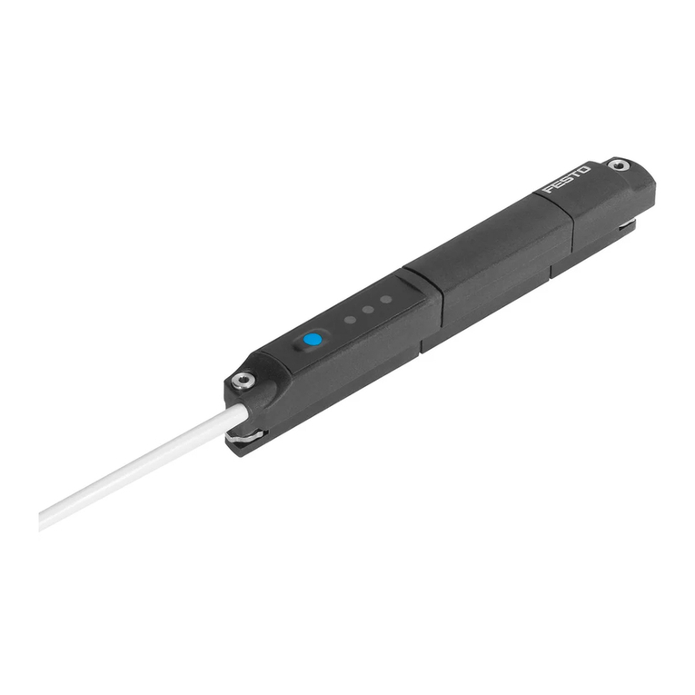
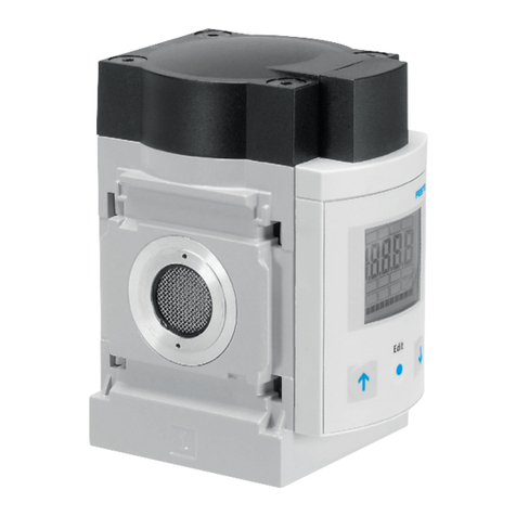
Festo SPAE User manual

SPAE
Pressure sensor
Operating instruc-
tion
8185191
8185191
2022-12c
[8185193]

Translation of the original instructions
IO-Link is a registered trademark of its respective trademark holder in certain countries.

Festo — SPAE — 2022-12c
3
Table of contents
1 Applicable Documents. . . . . . . . . . . . . . . . . . . . . . . . . . . . . . . . . . . . . . . . . . . . . . . . . . . . . . . . . . . . 4
2Safety. . . . . . . . . . . . . . . . . . . . . . . . . . . . . . . . . . . . . . . . . . . . . . . . . . . . . . . . . . . . . . . . . . . . . . . . . . 4
2.1 Safety instructions. . . . . . . . . . . . . . . . . . . . . . . . . . . . . . . . . . . . . . . . . . . . . . . . . . . . . . . . . . 4
2.2 Intended use. . . . . . . . . . . . . . . . . . . . . . . . . . . . . . . . . . . . . . . . . . . . . . . . . . . . . . . . . . . . . . 4
2.3 Training of qualified personnel. . . . . . . . . . . . . . . . . . . . . . . . . . . . . . . . . . . . . . . . . . . . . . . . 4
2.4 Range of application and certification. . . . . . . . . . . . . . . . . . . . . . . . . . . . . . . . . . . . . . . . . . 4
3 Additional information. . . . . . . . . . . . . . . . . . . . . . . . . . . . . . . . . . . . . . . . . . . . . . . . . . . . . . . . . . . . 5
4 Product overview. . . . . . . . . . . . . . . . . . . . . . . . . . . . . . . . . . . . . . . . . . . . . . . . . . . . . . . . . . . . . . . . 5
4.1 Product overview . . . . . . . . . . . . . . . . . . . . . . . . . . . . . . . . . . . . . . . . . . . . . . . . . . . . . . . . . . . 5
4.1.1 Display components. . . . . . . . . . . . . . . . . . . . . . . . . . . . . . . . . . . . . . . . . . . . . . . . 5
4.1.2 Operating key. . . . . . . . . . . . . . . . . . . . . . . . . . . . . . . . . . . . . . . . . . . . . . . . . . . . . 7
4.2 Function. . . . . . . . . . . . . . . . . . . . . . . . . . . . . . . . . . . . . . . . . . . . . . . . . . . . . . . . . . . . . . . . . . 7
4.2.1 Operating statuses. . . . . . . . . . . . . . . . . . . . . . . . . . . . . . . . . . . . . . . . . . . . . . . . . 7
4.2.2 Switching functions. . . . . . . . . . . . . . . . . . . . . . . . . . . . . . . . . . . . . . . . . . . . . . . . . 8
5Assembly. . . . . . . . . . . . . . . . . . . . . . . . . . . . . . . . . . . . . . . . . . . . . . . . . . . . . . . . . . . . . . . . . . . . . . . 9
5.1 Mounting sensor on mounting clip. . . . . . . . . . . . . . . . . . . . . . . . . . . . . . . . . . . . . . . . . . . . 9
5.2 Mounting sensor on plate. . . . . . . . . . . . . . . . . . . . . . . . . . . . . . . . . . . . . . . . . . . . . . . . . . . 10
5.3 Mounting sensor on QS plug connector. . . . . . . . . . . . . . . . . . . . . . . . . . . . . . . . . . . . . . . 10
6 Installation. . . . . . . . . . . . . . . . . . . . . . . . . . . . . . . . . . . . . . . . . . . . . . . . . . . . . . . . . . . . . . . . . . . . 11
6.1 Installation, electrical. . . . . . . . . . . . . . . . . . . . . . . . . . . . . . . . . . . . . . . . . . . . . . . . . . . . . . 11
7Commissioning. . . . . . . . . . . . . . . . . . . . . . . . . . . . . . . . . . . . . . . . . . . . . . . . . . . . . . . . . . . . . . . . . 11
7.1 Displaying parameters in SHOW mode. . . . . . . . . . . . . . . . . . . . . . . . . . . . . . . . . . . . . . . . 11
7.2 Setting sensor in EDIT mode. . . . . . . . . . . . . . . . . . . . . . . . . . . . . . . . . . . . . . . . . . . . . . . . . 11
7.3 Teaching switching point in TEACH mode. . . . . . . . . . . . . . . . . . . . . . . . . . . . . . . . . . . . . . 12
7.4 Replicating parameters. . . . . . . . . . . . . . . . . . . . . . . . . . . . . . . . . . . . . . . . . . . . . . . . . . . . . 13
7.5 Menu structure. . . . . . . . . . . . . . . . . . . . . . . . . . . . . . . . . . . . . . . . . . . . . . . . . . . . . . . . . . . 15
8 Operation. . . . . . . . . . . . . . . . . . . . . . . . . . . . . . . . . . . . . . . . . . . . . . . . . . . . . . . . . . . . . . . . . . . . . 16
8.1 Restoring factory settings (Restore). . . . . . . . . . . . . . . . . . . . . . . . . . . . . . . . . . . . . . . . . . 16
9Fault clearance. . . . . . . . . . . . . . . . . . . . . . . . . . . . . . . . . . . . . . . . . . . . . . . . . . . . . . . . . . . . . . . . . 16
10 Removal. . . . . . . . . . . . . . . . . . . . . . . . . . . . . . . . . . . . . . . . . . . . . . . . . . . . . . . . . . . . . . . . . . . . . . . 17
11 Technical data. . . . . . . . . . . . . . . . . . . . . . . . . . . . . . . . . . . . . . . . . . . . . . . . . . . . . . . . . . . . . . . . . . 17
11.1 Technical data for UL/CSA certification . . . . . . . . . . . . . . . . . . . . . . . . . . . . . . . . . . . . . . . . 20

4
Festo — SPAE — 2022-12c
Safety
1 Applicable Documents
All available documents for the product èwww.festo.com/sp.
2 Safety
2.1 Safety instructions
–Only use the product in its original condition without unauthorised modifications.
–Only use the product if it is in perfect technical condition.
–Observe the identifications on the product.
–Before working on the product, switch off the compressed air supply and lock it to prevent it from
being switched on again.
–Only use media in accordance with the specifications è Technical data.
–The product may generate high frequency interference, which may require interference suppression
measures in residential areas.
2.2 Intended use
The sensor records the relative pressure in pneumatic applications.
2.3 Training of qualified personnel
Work on the product may only be carried out by qualified personnel who can evaluate the work and
detect dangers.
The qualified personnel have skills and experience in dealing with electropneumatic (open-loop)
control technology.
2.4 Range of application and certification
In combination with the UL inspection mark on the product, the information in this section must also
be observed in order to comply with the certification conditions of Underwriters Laboratories Inc. (UL)
for USA and Canada.
UL approval information
Product category code QUYX2 (USA)
or QUXY8 (Canada)
File number E322346
Considered standards UL 61010-1
CAN/CSA 22.2 No. 61010-1
UL mark
Tab. 1: UL certification information

Festo — SPAE — 2022-12c
Product overview
5
Conditions of Acceptability
For use only in or with complete equipment where the acceptability of the combination is determined
by UL LLC. When installed in an end-product, consideration must be given to the following:
–This component has been judged on the basis of the creepage and clearances required in the
indicated Standards, which would cover the component itself if submitted for Listing: CAN/CSA 22.2
No. 61010-1-12 3rd Ed., UL 61010-1 3rd Ed.
–The end-product shall consider that: The enclosure does not serve as a fire/electrical/mechanical
enclosure.
–The output connectors are: Not investigated for field wiring.
–The unit is considered acceptable for use in a max ambient of: 50°C.
3 Additional information
–Contact the regional Festo contact if you have technical problems èwww.festo.com.
–Accessories and spare parts èwww.festo.com/catalogue.
4Product overview
4.1 Product overview
2 3 4
56
1
Fig. 1: Design
1
LEDs
2
Display
3
Operating key
4
Electrical connection
5
Blanking plug, dependent on type
6
Pneumatic port, design dependent on type
4.1.1 Display components
LED Display Meaning
Both LEDs on Continuously on RUN mode: switching output switched
Both LEDs off Continuously on RUN mode: switching output not switched

6
Festo — SPAE — 2022-12c
Product overview
LED Display Meaning
One LED flashes Continuously on RUN mode: IO-Link communication active
Both LEDs off Function and Value flash
alternately
SHOW mode
Both LEDs flash alter-
nately
Continuously on or
flashing
EDIT mode: first menu option
Both LEDs flash simulta-
neously
Continuously on or
flashing
EDIT mode: second menu option or TEACH mode
Tab. 2: LEDs
Display Meaning
<Value> In RUN mode: current measured value in % FS
Single-digit pressure display values are displayed with a preceding under-
score,e.g._1
‘F0’ Switching function F0 è4.2.2 Switching functions
‘F1’ Switching function F1 è4.2.2 Switching functions
‘F2’ Switching function F2 è4.2.2 Switching functions
‘F3’ Switching function F3 è4.2.2 Switching functions
Threshold value comparator
Window comparator
‘P1’ Switching point P1 in % FS
‘P2’ Switching point P2 in % FS; not with switching function F0 and F1
‘HY’ Hysteresis in % FS:
Adjustable from 0…99, corresponds to 0 to 9.9% FS; not with switching function F2
‘Lo’ Minimum measured value in % FS
‘Hi’ Maximum measured value in % FS
‘Pn’ PNP switching output
‘nP’ NPN switching output
‘nc’ Switching logic normally closed contact
‘no’ Switching logic normally open contact
‘di’ Switch display on and off:
‘On’ = always on; ‘1’…‘20’ = switch off after 1…20 minutes
‘do’ Aligning the numeric indicator on the display:
‘do’ = default alignment; ‘op’ = rotated 180°
‘op’

Festo — SPAE — 2022-12c
Product overview
7
Display Meaning
‘LC’ Enabling and disabling the security code:
‘OF’ = security coded deactivated; ‘On’ = security coded activated;
‘1’…‘99’ = security code
‘rP’ IO-Link master function to replicate parameters:
‘On’ = replicate on; ‘OF’ = replicate off
Tab. 3: Display
4.1.2 Operating key
The operating key is used to select switching functions and set parameters. The function of the
operating key is time and context-dependent. If the operating key is not actuated for approx. 12
seconds during the setting procedure, the sensor will automatically switch to the RUN mode. Changed
setting values are accepted. Exceptions: TEACH mode and display min./max. measured values.
4.2 Function
The sensor converts pneumatic pressure values into a voltage proportional to the pressure. The
measurement is made using a piezoresistive sensor element.
The connection to the higher-level system is established via a switching output or a IO-Link interface.
The switching output can be configured to monitor a threshold value or a pressure range. The PNP
or NPN and the normally open (N/O) or normally closed (N/C) output can be optionally set in this
process.
The process values can be read out and parameters changed and transmitted to additional devices
through the IO-Link interface.
4.2.1 Operating statuses
Operating status Function
RUN mode –Basic state after the operating voltage has been applied.
–Display of the current measured value.
–Display of the selected switching status.
SHOW mode –Display of the current settings.
EDIT mode –Setting or modification of parameters.
TEACH mode –Acceptance of the current measured value to determine the switching
point.
Tab. 4: Operating statuses

8
Festo — SPAE — 2022-12c
Product overview
4.2.2 Switching functions
Threshold value comparator
Function Normally open contact (N/O) Normally closed (N/C contact)
F0:
Switching function:
–Threshold value comparator
–1 switching point (P1)
TEACH mode:
–1 teach-in point (tP)
–tP = P1
F1:
Switching function:
–Threshold value comparator
–1 switching point (P1)
TEACH mode:
–2 teach-in points (TP1, TP2)
–P1 = ½ (tP1 + tP2)
F2:
Switching function:
–Threshold value comparator
–2 switching points (P1, P2)
TEACH mode:
–2 teach-in points (TP1, TP2)
–tP1 = P1, tP2 = P2
Tab. 5: Threshold value comparator
Window comparator
Function Normally open contact (N/O) Normally closed (N/C contact)
F3:
Switching function:
–Window comparator
–2 switching points (P1, P2)
TEACH mode:
–2 teach-in points (TP1, TP2)
–tP1 = P1, tP2 = P2
Tab. 6: Window comparator

Festo — SPAE — 2022-12c
Assembly
9
5 Assembly
NOTICE
An unfavourable mounting position may impair the function of the product.
• When selecting the mounting position, make sure that condensate from the compressed air lines
cannot accumulate in the sensor.
5.1 Mounting sensor on mounting clip
Product variant SPAE-...-Q... and mounting clip SAMH
Fig. 2: Mounting clip SAMH
1. Slide the sensor into the mounting clip with the cable outlet at the top or with the cable outlet at
the bottom.
2. If the tubing is on one side, close the unused pneumatic port with a blanking plug.
Fig. 3: SPAE-...-Q...

10
Festo — SPAE — 2022-12c
Assembly
5.2 Mounting sensor on plate
Product variant SPAE-...-F
Fig. 4: Flange hole pattern SPAE-…-F1)
1) Pressure port hole: maximum Æ 2 mm
–Check that the sealing ring is correctly seated.
M2
max. 0,3 Nm
Fig. 5: SPAE-...-F
5.3 Mounting sensor on QS plug connector
Product variant SPAE-...-S...
• Insert the sensor into the QS plug connector to the stop.
Fig. 6: SPAE-...-S...

Festo — SPAE — 2022-12c
Commissioning
11
6 Installation
6.1 Installation, electrical
WARNING
Risk of injury due to electric shock.
• For the electric power supply, use only PELV circuits that ensure a reliable electric disconnection
from the mains network.
• Observe IEC60204-1/EN60204-1.
• Connect the sensor.
–Note maximum permissible cable lengths è11 Technical data.
–Only route the signal line and power supply in a common line.
Circuit diagram and wire assignment
Circuit diagram Core colour Allocation
Brown (BN) Operating voltage +24 V DC
Black (BK) Switching output or IO-Link (C/Q line)
Blue (BU) 0V
Tab. 7: Circuit diagram
7Commissioning
7.1 Displaying parameters in SHOW mode
Requirement: the sensor is ready for operation and is in RUN mode.
1. Press the operating key briefly.
ÄThe sensor is in SHOW mode. The first parameter set is displayed.
2. Press the operating key to display each of the following parameters.
ÄThe other parameters are displayed.
7.2 Setting sensor in EDIT mode
Requirement: the sensor is ready for operation and is in RUN mode.
Entering security code
If the security code is enabled, the parameter entry option is blocked: ‘LC’ flashes briefly, then the
value 1 appears.
1. Press the operating key repeatedly until the security code is set.
2. Press and hold the operating key.
ÄThe parameter entry option is unblocked.

12
Festo — SPAE — 2022-12c
Commissioning
Setting the switching function
1. Press the operating key once.
ÄThe display alternates between the designation and the symbol of the currently set switching
function.
2. Press and hold the operating key to switch to EDIT mode.
ÄThe LEDs flash alternately.
3. Press the operating key repeatedly until the desired switching function appears in the display.
4. Press and hold the operating key.
ÄThe setting is saved.
ÄThe RUN mode is active.
Setting switching points and hysteresis
–The hysteresis display value corresponds to 10 times the actual value, e.g.the value of the value 10
corresponds to a hysteresis of1.0%FS.
–Parameters ‘P2’ and ‘HY’ are only displayed if they are intended for the set switching function
è4.2.2 Switching functions.
–The values can be set in two stages with a rough adjustment in steps of ten and a precision
adjustment in steps of one.
1. Press the control button repeatedly until the required parameter appears on the display.
ÄThe display alternately shows the designation and the value of the currently set switching
function.
2. Press and hold the operating button to switch to the EDIT mode and make the rough adjustment.
ÄThe LEDs flash alternately.
3. Press the operating key repeatedly until a value is displayed that is equal to, or slightly less than,
the desired value.
4. Press and hold the operating key to make the precision adjustment.
ÄThe LEDs flash simultaneously.
5. Press the operating key repeatedly until the desired value is displayed.
6. Press and hold the operating key to save the setting.
ÄThe RUN mode is active.
7.3 Teaching switching point in TEACH mode
Requirement: the sensor is ready for operation and is in RUN mode.
Entering security code
The teach function is blocked when the security code is activated.
•Enable parameter entry èEntering security code.
Setting switching point with a teach pressure at F0
1. Apply the teach pressure to the sensor.

Festo — SPAE — 2022-12c
Commissioning
13
2. Press and hold the operating key to accept the teach pressure as the switching point.
The display alternates between ‘P1’ and the value of the set switching point while the operating
key is pressed.
ÄThe teach pressure is applied as the switching point.
3. Release the operating key.
ÄThe RUN mode is active.
Setting switching point with two teach pressures
1. Apply the first teach pressure to the sensor.
2. Press and hold the operating key to accept the teach pressure as the switching point.
The display alternates between ‘tP’ and the value of the set switching point while the operating
key is pressed.
ÄThe teach pressure is set as the switching point.
3. Release the operating key.
4. Apply the second teach pressure to the sensor.
5. Press and hold the operating key to accept the teach pressure as the switching point.
The display alternates between ‘tP’ and the value of the set switching point while the operating
key is pressed.
ÄThe teach pressure is set as the switching point.
6. Release the operating key.
ÄSwitching function F1 only: ‘P1’ and the value of the switching point P1 briefly appear.
ÄThe RUN mode is active.
7.4 Replicating parameters
Requirements:
–The previously configured sensor (master sensor) is ready for operation and is in RUN mode.
–The switching output on the device sensor is configured to PNP and is in an unswitched status; the
LED is off.
–The master sensor and device sensor have the same design with reference to the parameters,
i.e.they have the same device ID.
–The master sensor is connected to the device sensor and the power supply èFig. 7.
–Parameterisation of the device sensor must not be blocked via IO-Link.

14
Festo — SPAE — 2022-12c
Commissioning
Fig. 7: Terminal allocation
On the configured sensor (master):
1. Press the operating key repeatedly until ‘rP’/‘OF’ appears.
2. Press and hold the operating key.
Ä‘rP’/‘On’ briefly appears.
ÄAfter successful replication ‘rP’/‘OF’ appears. If an error occurs, an error message will appear
briefly è9 Fault clearance.
3. If an additional sensor is to be parameterised, connect the additional sensor and repeat step 1
and step 2.
4. Press the operating key briefly.
ÄThe RUN mode is active.

Festo — SPAE — 2022-12c
Commissioning
15
7.5 Menu structure
Fig. 8: Menu structure
If the value ‘nP’ is selected when setting the switching output, operation of the IO-Link is not possible.

16
Festo — SPAE — 2022-12c
Fault clearance
8 Operation
8.1 Restoring factory settings (Restore)
Restoring the factory settings will delete the current settings.
1. Switch off the operating voltage.
2. Press and hold the operating key.
3. Switch on the operating voltage.
ÄA value appears.
Ä‘--’ appears.
Ä‘rS’ appears.
4. Release the operating key.
9 Fault clearance
Malfunction Cause Remedy
No display No operating voltage or unreli-
able operating voltage
–Apply permissible operating
voltage
Electrical connections swapped –Connect the device in accord-
ance with the circuit diagram
Device faulty –Replace device
No measured value indicator in
the RUN mode
Display switch-off activated –Press the operating key
–Set ‘On’ value
Display flashes in the RUN mode Measuring range exceeded –Hold measuring range
Implausible measured value Wrong display orientation –Check the orientation of the
display
Indicator or switching output
does not respond in accordance
with the settings
Short circuit or overload at
output
–Eliminate short circuit/over-
load
Incorrect switching point set –Repeat teach-in
Device faulty –Replace device
Display ‘Er’/‘LC’ Incorrect security code –Entering security code
Display ‘Er’/‘Co’ IO-Link communication error –Check setting of the device
sensor (Pn)
–Check line
Display ‘Er’/‘Id’ Device ID error, devices do not
have the same design
–When replicating, use sensors
with the same pressure range
(same device ID)

Festo — SPAE — 2022-12c
Technical data
17
Malfunction Cause Remedy
Display ‘Er’/‘bY’ Switching output is active –Check device settings
Display ‘Er’/‘01’ Device error –Replace device
Display ‘Er’/‘17’ Undervoltage –Apply permissible operating
voltage
Display ‘Er’/‘20’ Temperature fault –Check operating conditions
–Replace device
Display ‘Er’/‘21’ Short circuit –Eliminate short circuit
Tab. 8: Fault clearance
10 Removal
1. Switch off the operating voltage and the compressed air.
2. Disconnect the electrical and pneumatic connections from the sensor.
3. Release the fasteners and remove the sensor.
–Release the latch when using mounting clips.
11 Technical data
General
Certification RCM Mark, c UR us – Recognized
Declaration of conformity èwww.festo.com/sp
Tab. 9
Input signal/measuring element
Operating medium Compressed air in accordance with ISO
8573-1:2010 [7:4:4], lubricated operation pos-
sible
Temperature of medium [°C] 0…50
Ambient temperature [°C] 0…50
Tab. 10
Output, general
Accuracy at room temperature [%FS] ± 1.5
Accuracy in ambient temperature range [%FS] ± 2.5

18
Festo — SPAE — 2022-12c
Technical data
Output, general
Repetition accuracy [%FS] ± 0.3
Temperature coefficient [%FS/K] Typ. ± 0.05
Tab. 11
Switching output
Switch-on time [ms] Typ. 1, with filter time constant = Off (default)
Switch-off time [ms] Typ. 1, with filter time constant = Off (default)
Max. output current [mA] 100
Capacitive load maximum DC [nF] 100
Voltage drop [V] Max. 1.2
Inductive protective circuit Present
Tab. 12
Output, additional data
Short circuit current rating Yes
Overload protection Present
Tab. 13
Electronics
Operating voltage range DC [V] 18…30
No-load supply current [mA] < 11
Ready-state delay [ms] < 30
Reverse polarity protection All connections against one other
Tab. 14
Electromechanics
Electrical connection Cable 3-wire, open end
Max. permissible line length [m] 30, with IO-Link 20
Cable sheath material PVC
Tab. 15

Festo — SPAE — 2022-12c
Technical data
19
Mechanics
Mounting position Any, avoid condensation accumulation in the
sensor
Housing material Reinforced PA
Key material POM
Tab. 16
Immission/Emission
Storage temperature [°C] –20…+80
Degree of protection in accordance with
EN60529
IP40
Protection class in accordance with
DIN VDE 0106-1
III
Shock resistance in accordance with
EN60068-2
30 g acceleration with 11 ms duration (half-sine)
Vibration resistance in accordance with
EN60068-2
10…60Hz: 0.35mm/
60…150Hz: 5g
Pollution degree 3
Tab. 17
SPAE -B2 -B11 -V025 -V05 -V1
Pressure
gauge
range
[MPa] –0.1…0.1 –0.1…1 0…–0.025 0…–0.05 0…–0.1
[bar] –1…1 –1…10 0…–0.25 0…–0.5 0…–1
[psi] –14.5…14.5 –14.5…145 0…–3.625 0…–7.25 0…–14.5
Overload
range
[MPa] –0.1…0.5 –0.1…1.5 –0.1…0.1 –0.1…0.2 –0.1…0.5
[bar] –1…5 –1…15 –1…1 –1…2 –1…5
[psi] –14.5…72.5 –14.5…217.5 –14.5…14.5 –14.5…29 –14.5…72.5
Tab. 18

20
Festo — SPAE — 2022-12c
Technical data
SPAE -P025 -P05 -P1 -P2 -P6 -P10
Pressure
gauge
range
[MPa] 0…0.025 0…0.05 0…0.1 0…0.2 0…0.6 0…1
[bar] 0…0.25 0…0.5 0…1 0…2 0…6 0…10
[psi] 0…3.625 0…7.25 0…14.5 0…29 0…87 0…145
Overload
range
[MPa] –0.1…0.1 –0.1…0.2 –0.1…0.5 –0.1…0.6 –0.1…1.5 –0.1…1.5
[bar] –1…1 –1…2 –1…5 –1…6 –1…15 –1…15
[psi] –14.5…
14.5
–14.5… 29 –14.5…
72.5
–14.5… 87 –14.5…
217.5
–14.5…
217.5
Tab. 19
IO-Link
IO-Link protocol V1.1
IO-Link profile Smart Sensor Profile
Function classes: 0x8000, 0x8001, 0x8002,
0x8003, 0x8004
Communication mode COM2 (38.4 kbaud)
Port type A
Process data length IN 2 bytes
Process data content IN Pressure monitoring BDC1 (BinaryDataChannel1)
Pressure monitoring BDC2 (BinaryDataChannel2)
Pressure measurement value PDV 14 bit (Process-
DataVariable)
IODD and IO-Link device description èwww.festo.com
Tab. 20: General IO-Link specification
11.1 Technical data for UL/CSA certification
Ambient conditions UL/CSA
Pollution degree 2
Operating temperature 0…50 °C/ 32…122 °F
Relative humidity 0…100%
For use in wet locations No
Tab. 21: Ambient conditions UL/CSA
Table of contents
Other Festo Accessories manuals

Festo
Festo VMPAF-FB-PS Series User manual

Festo
Festo SOOE-RS PNLK-T Series User manual

Festo
Festo SRBG User manual

Festo
Festo SFAM User manual

Festo
Festo SDAP-...-M50-Series User manual

Festo
Festo SDE1 Series User manual

Festo
Festo SFAW Series User manual

Festo
Festo SRBC Series User manual

Festo
Festo SFAB User manual

Festo
Festo SOPA-C series User manual

Festo
Festo SRAP-M-CA1 Series User manual

Festo
Festo SPAN-B Series User manual

Festo
Festo SFAB-10U User manual

Festo
Festo SPAW series User manual

Festo
Festo SOEG-S-Q20 series User manual

Festo
Festo SBSI-EN Service manual

Festo
Festo SFAW User manual

Festo
Festo SBSI-EN User manual

Festo
Festo Span Series User manual

Festo
Festo NECA-S1G9-P9-MP3-SA User manual