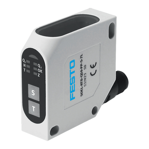
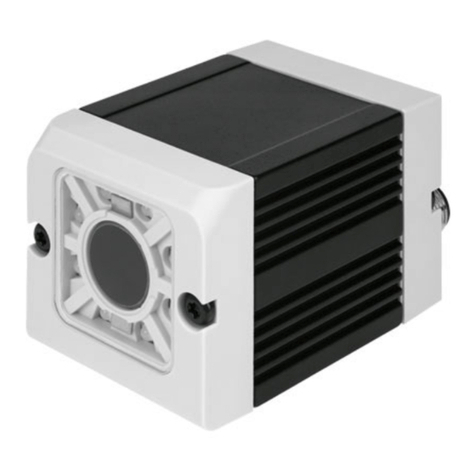
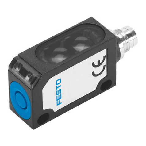
Vision Sensor Mounting and operating instructions
Table of Contents
1 General Information and Safety 5
1.1 Safety notes 5
1.2 Components supplied 5
1.3 Requirements for use 5
2 Intended Use 6
2.1 Field of application 6
2.2 Functions overview 7
2.3 Sensor types 8
2.3.1 Object detection 8
2.3.2 Code Reader 8
2.4 Field of view / Depth of view 10
3 Installation 13
3.1 Mechanical Installation 13
3.1.1 Arrangement for dark-field illumination 13
3.1.2 Arrangement for bright-field illumination 14
3.1.3 Alignment for a vertical illumination 15
3.1.4 Assembly Vision Sensor - Mounting bracket SBAM-C6-CP 16
3.2 Electrical installation 16
3.2.1 Connection possibilities 17
3.2.1.1 LED Display 17
3.2.1.2 Focussing screw 18
3.2.1.3 24 V DC Connection 18
3.2.1.4 LAN Connection 18
3.2.1.5 Data Connection 18
3.2.2 Plug connections 19
3.2.2.1 PIN assignment, connection 24 V DC 19
3.2.2.2 PIN assignment, connection LAN 19
3.2.2.3 PIN assignment DATA *A) 20
3.2.2.4 Exemplary connection plan and software settings for the following setup: 20
3.2.2.5 Electrical connection supply voltage and shield 21
3.2.2.6 Electrical connection PNP / NPN 21
3.3 Network settings, Short reference 22
3.3.1 Basic settings for PC and Vision Sensor 22
3.3.2 Direct Connection - Setting the IP Address of the PC 23
3.3.3 Network Connection - Setting the IP address of the Vision Sensor 24
4 Vision Sensor – Operating- and configuration software 26
4.1 Vision Sensor – Operating- and configuration software - Overview 26
4.1.1 Structure of PC software 26
4.1.2 Context help 26
4.2 Vision Sensor – Operating- and configuration software – Short introduction 27
4.2.1 Vision Sensor, Short introduction, Starting the software 27
4.2.2 Vision Sensor Device Manager: Open sensors or sensor simulation / Passwords 27
4.2.3 Passwords 29
4.2.4 Password levels: 29
4.3 Vision Sensor Configuration Studio: Setting sensor, Job 31
4.3.1 Job Setup 32
Vision Sensor SBSI-EN, 8033107 - 1401N12.05.2014 Page 3


