Fitting instructions
ã(Festo AG & Co., D-73726 Esslingen, 1999) Part no.: 396 436
Internet: http://www.festo.com 9910a
e-mail: service_international@festo.com
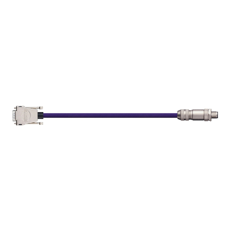
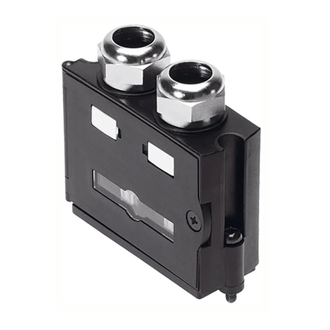
Field bus plug FBS-SUB-9-GS-9 (TN 18529)
1screw
2union nut
3sealing ring
4screw connector,
lower part
5upper cover
6seal
7circuit board
8cable clip
9terminal block
aJ lower cover
aA countersunk screw
Fitting
1. Insert seals 6into upper and lower covers 5+aJ .
2. Insert the printed circuit board 7into the guide of the lower
cover.
3. Fasten the printed circuit board to the lower cover with
countersunk screws aA.
4. Screw the lower part of the screw connector 4into the upper
cover as far as it will go.
5. Thread the union nut 2and sealing ring 3onto the bus cable.
Pass the bus cable through the upper cover.
6. Remove part of the insulation from the bus cable (Fig. 2) and
connect to terminal block 9. Clamp the screening with the cable
clip 8 to the printed circuit board.
7. Push the upper cover onto the printed circuit board 7and latch
with the lower cover.
8. Screw the union nut 2and seal ring 3together with the lower
part of the screw connector 4.
9. Insert screws 1as far as they will go into the plug housing and
then screw them in under pressure with a screwdriver until they
project 1 to 2 mm out of the lower cover.
Caution
•Switch on the terminating resistors both at the start and at the end
of the segment (Fig. 3). If the bus cable is looped through, the
terminating resistors must not be switched on.
•At the start and end of the segment a cable exit must be closed
with the plug supplied (Fig. 3).
The screening braiding must be clamped uninsulated under the cable
clip.
65 10
Fig. 2: Removing insulation from the bus cable (dimensions in mm)
Fig. 1: Individual parts of the plug Fig. 3: Switch for bus termination, plug
6
aJ
aA
6
7
8
9
5
4
3
2
1
Bus termination
enabled not
enabled
