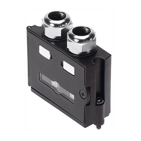
Product design of the central lubrication system EGC-HD-BS-C
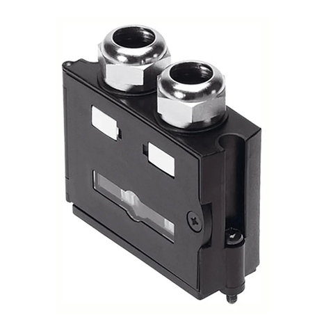
1Lubrication adapter
2Lubrication port on rear guide,
rear
3Lubrication port on front guide,
front
4Lubrication port with ball screw
drive
Fig. 5 Product design of the central lubrication system EGCHDBSC
Product design of the central lubrication system EGC-HD-TB-C
1Lubrication adapter
2Lubrication port on rear guide,
rear
3Lubrication port on front guide,
front
Fig. 6 Product design of the central lubrication system EGCHDTBC
6 Assembly
6.1 Safety
WARNING!
Risk of Injury due to Unexpected Movement of Components
For vertical or slanted mounting position: when power is off, moving parts can
travel or fall uncontrolled into the lower end position.
• Bring moving parts of the product into a safe end position or secure them
against falling.
6.2 Fasten the central lubrication system supply line
Reducing load on the supply line
Attach the supply line to the lubrication adapter only in combination with a strain
relief
Connect central lubrication system DGC-C, DGC-FA-C, DGCI-C
Restriction of the central lubrication system connections
When using shock absorbers, shock absorber retainers with stops or lateral pro
file mounting the number of permissible connection variants for the central lubric
ation system is reduced.
Profile mounting MUC
underneath at the side, rear
DGC8/.../63C
DGC8 /.../ 63FAC
DGCI18 /.../ 63C
DGC18/.../63C
DGC18 /.../ 63FAC
DGCI18 /.../ 63C
without cushioning
with elastic cushioning P
with pneumatic cushioning PPV
with shock absorber YSR / YSRW
Profile mounting MUC
underneath at the side, rear
with shock absorber retainer DADP and stop KYC
–
Tab. 1 Overview DGC... C, permissible connections for central lubrication system
1Lubrication adapter
2Fitting or threaded pin
3Supply lines for central lubrication
system, guide
Fig. 7 Connect central lubrication system DGCC, DGCFAC, DGCIC (example: sup
ply cable at top)
– Lubrication port: guide at both ends; front, top or rear
1. Remove threaded pins2.
2. Mount fittings2. (tightening torque è Tab. 2 Information for fitting)
3. Connect guide for central lubrication system supply lines3. (2x)
Connect central lubrication system EGC-C
1Lubrication adapter
2Fitting or threaded pin
3Supply lines for central lubrication
system, guide
4Supply line for central lubrication
system, ball screw drive
Fig. 8 Connect central lubrication system EGCBSC (example: supply line at top)
1Lubrication adapter
2Fitting or threaded pin
3Supply lines for central lubrication
system, guide
Fig. 9 Connect central lubrication system EGCTBC / EGCFAC (example: supply
line at top)
– Lubrication connection for guide (KF): at both ends; front, top or rear
– Lubrication port with ball screw drive (BS): one end; at the front
1. Remove threaded pins2.
2. Mount fittings2. (tightening torque è Tab. 2 Information for fitting)
3. Connect guide for central lubrication system supply lines3. (2x)
4. Connect supply line to ball screw drive central lubrication system4. (only
BS: 1x)
