manuals.online logo
Brands
  1. Home
  2. •
  3. Brands
  4. •
  5. Festo
  6. •
  7. Cables And Connectors
  8. •
  9. Festo CTEU-AS Operating and installation instructions

Festo CTEU-AS Operating and installation instructions

Bus node
CTEU-AS
Festo AG & Co. KG
Postfach
73726 Esslingen
Germany
+49 711 347-0
www.festo.com
Description
Installation and interfaces
8032384
1405NH
[8032386]
Original: de
Bus node CTEU-AS English.............................................
1 Instructions on this description
This description includes information for mounting the bus node on an I-port-com-
patible device from Festo (e.g. valve terminal with I-port interface) and for installa-
tion of this combination in a higher-level control system.
AS-Interface
®
and TORX
®
are registered trademarks of the respective
trademark owners in certain countries.
2Intendeduse
The bus node type CTEU-AS has been designed exclusively for use as a slave on
the AS-interface fieldbus. It may only be used in its original status without unau-
thorised modifications and only in perfect technical condition.
The bus node is intended for use in an industrial environment. Outside of industrial
environments, e.g. in commercial and mixed-residential areas, actions to suppress
interference may have to be taken.
3Targetgroup
The target group for this description consists of trained specialists in control and
automation technology who have experience with installation of stations on the
AS-interface fieldbus.
4Mounting
Warning
Danger of injury to people, damage to the machine and system resulting from
uncontrolled movements of the actuators and undefined switching states
• Switch off the operating and load voltage supplies.
• Switch off compressed air supply.
• Exhaust the pneumatics valve terminal.
Note
Damage to the electronics
The bus node includes electrostatically sensitive devices.
• Do not touch any electrical/electronic components.
• Observe the handling specifications for electrostatically sensitive devices.
Note
Use cover caps to seal unused connections. You will then achieve degree of pro-
tection IP65/IP67.
Information on mounting the bus node on the decentralised electrical
connecting plate CAPC-... can be found in the mounting instructions that
accompany the connecting plate.
The bus node CTEU-AS supports only the X1 connection of the electrical
connecting plate CAPC-.... The X2 connection on the electrical connecting
plate CAPC-... is without a function for the CTEU-AS bus node.
For mounting the bus node on a valve terminal with I-Port interface, proceed as
follows:
1. Inspect the seals and sealing surfaces on bus node and valve terminal.
2. Plug the bus node onto the valve terminal in the right position and without tilt-
ing.
3. Screw the three self-tapping screws in by hand. You can use the threads already
present when you screw it in again.
4. Tighten the screws by hand in diagonally opposite sequence, with a tightening
torque of 0.7 ± 0.1 Nm.
5 Connection and display components
The following electrical connection and display components can be found on the
bus node:
1
3
4
2
1DIL switch group (chap. 7.2)
2Status LEDs (status display/
diagnostics chap. 8)
3M12 plug for AS-interface bus and
additional power supply (AS-i In)
(chap. 6)
4M12 socket, AS-interface bus and
additional power supply (AS-i Out)
(chap. 6 )
Fig. 1
6 Connect AS-interface bus and auxiliary power supply
The bus node also supplies voltage to equipment connected via the I-port inter-
face.
Warning
Danger of electric shock
• Only use PELV circuits in accordance with IEC/EN 60204-1 (protective extra-
low voltage, PELV) for the electrical power supply.
• Observe also the general requirements for PELV power circuits in accordance
with IEC/EN 60204-1.
• Only use voltage sources which guarantee reliable electrical isolation of the
operating voltage in accordance with IEC/EN 60204-1.
Through the use of PELV circuits, protection against electric shock (protection
against direct and indirect contact) is ensured in accordance with IEC/EN 60204-1.
Observe with branch lines:
– the maximum overall length of the AS-interface bus (100 m without repeater/
extender)
– the line length of the load voltage connection cable (depends on the current
consumption of the valve terminal and fluctuations in load voltage).
M12 plug, AS-interface In Pin Allocation
1
3
2
41AS-interface +
20 V (auxiliary power supply)
3AS-interface –
424 V (auxiliary power supply)
Fig. 2
M12 socket, AS-interface Out Pin Allocation
4
23
11AS-interface +
20 V (auxiliary power supply)
3AS-interface –
424 V (auxiliary power supply)
Fig. 3
Note
Electromagnetic interference
• Make the connection to functional earth via the connected device or the elec-
trical connecting plate CAPC-....
Functional test:
– The LED “PS” is illuminated green when the power supply is correctly presented.
– The LED “X1” is lit green if a device is connected and the I-Port communication is
ready to function (chap. 8).
7 Basic settings for fieldbus communication
7.1 Removal of the DIL switch cover
To set the DIL switches, the cover must be removed:
1. Switch off the power supply.
2. Unscrew the two mounting screws of the transparent cover and remove the
cover.
7.2 Setting the DIL switches
The bus node has a DIL switch group with 2 DIL switches. Set the valve configura-
tion with DIL switches 1 and 2.
1
1DILswitches1and2
Fig. 4
I/O configuration,
AS-interface slaves
Valve configuration DIL
switches
1 2
8I/8O – The first 8 solenoid coils are actuated.
– The number of valves is not checked.
– The profile for both AS-interface slaves is 7.A.7
(factory setting).
OFF OFF
16 I/16 O – The first 16 solenoid coils are actuated.
– The number of valves is not checked.
– The profile for both AS-interface slaves is 7.A.A.
ON OFF
4I/4O – The first 4 solenoid coils are actuated.
– The number of valves is not checked.
– The profile of the AS-interface slave is 7.F.E.
(standard slave).
OFF ON
–Reserved ON ON
Fig. 5
7.3 Mounting of the DIL switch cover
1. Place the cover carefully on the bus node. Make sure that the seal is seated
correctly!
2. Tighten the mounting screws with max. 0.4 Nm with a Torx screwdriver
(size T10) or a slot screwdriver that fits.
7.4 Address allocation
Before connecting to the AS-Interface bus: Assign a free address to the slave.
Addressing can be performed via an AS-interface addressing device in accordance
C.S.2.1, an addressing cable and through an AS-interface master.
The number of connected solenoid coils is set through the DIL switches
(chap. 7.2). Depending on this setting, the number of slave addresses, IO and
ID code are automatically configured and saved (subsequent table).
Number of
solenoid coils
Slave
address
Profile 1 Profile 2 AS-interface-
master type
1…4 1Standard S-7.F.E –M1 … M4
1…8 1ExtendedA+B S-7.A.7 S-7.A.7 M4
1…16 1ExtendedA+B S-7.A.A S-7.A.A M4
Fig. 6
Assignment of slave addresses to physical outputs/valves of the connec-
ted devices can be found in the respective product documentation.
8 Status display/diagnostics
8.1 Status display via LEDs
PS (power system) – X1 (I-port)
LED indicator Status and significance
PS X1
Both LEDs light green:
– additional voltage present
LED “PS” lights green, LED “X1” flashes green
– additional voltage present
– short circuit at a solenoid coil or other diagnosis of the I-port device
(peripheral area)
Both LEDs flash green:
– additional voltage missing
LED “PS” lights green, LED “X1” flashes red:
– additional voltage present
– no I-port device detected
– peripheral faults
LED “PS” illuminated green, LED “X1” illuminated red:
– additional voltage present
– short circuit/overload behind the AS-interface coil
– peripheral error, I-port connection interrupted
Fig. 7
AS-i (AS-interface)
LED
indicator
Status and significance
LED illuminated green:
– AS-interface voltage applied
– no error is present.
LED is off:
– AS-Interface voltage not applied
LED illuminated red:
– AS-interface address not set (equals 0)
– no communication
LED flashes red/green:
– peripheral fault (e.g. no additional voltage, no I-port)
Fig. 8
Note
AS-interface has an integrated watchdog function, which can be activated/deac-
tivated via the parameter bit P0.
Valid is:
–P0=1Watchdog activated (delivery status)
–P0=0Watchdog deactivated
If Watchdog is activated, the outputs are reset as soon as bus communication
malfunctions.
8.2 Error diagnostics via AS-interface bus
AS-interface
parameter-entry bits
Faults
P3 P2 P1 P0
– 1 1 0 short circuit/overload behind the AS-interface coil
– 1 0 1 no additional voltage
– 0 1 1 no I-port device found
– 1 0 0 short circuit at a solenoid coil
Fig. 9
9Technicaldata
General
Degree of protection through housing
(in accordance with EN 60529)
IP65/67
1) 2)
AS-interface specification 3.0
Protection against electric shock
(Protection against direct and indirect contact in
accordance with IEC/DIN 60204-1)
Through use of PELV circuits
Electromagnetic compatibility (EMC)
3)
– emitted interference
– resistance to interference
See declaration of conformity
www.festo.com
Vibration and shock
(as per EN 60068)
Severity level (SL)
4)
for mounting on
– vibration (part 2 – 6) Wall: SG 2, H-rail: SG 1
– shock (part 2 – 27) Wall: SG 2, H-rail: SG 1
– continuous shock (part 2 – 29) Wall and H-rail: SG 1
Temperature range
– storage/transport –20…+70°C
2)
– environment, operation –5 … +50 °C
2)
Materials PA (reinforced), PC, NBR, steel (galvanized),
RoHS-compliant circuit boards
1) Requirement: Bus node mounted completely, plug connector in the plugged-in status or provided with
cover cap.
2) Note that connected devices may only satisfy a lower degree of protection, a smaller temperature
range, etc.
3) The bus node is intended for use in an industrial environment. Outside of industrial environments,
e.g. in commercial and mixed-residential areas, actions to suppress interference may have to be taken.
4) Explanation of the severity level subsequent tables
Fig. 10
Vibration load
Frequency range [Hz] Acceleration [m/s
2
]Deflection [mm]
Severity
level 1
SL2 SL1 SL2 SL1 SL2
2…8 2…8 ––±3.5 ±7
8…27 8…27 10 10 – –
27 … 58 27 … 60 ––±0.15 ±0.75
58 … 160 60 … 160 20 50 – –
160 … 200 160 … 200 10 10 – –
Fig. 11
Shock load
Acceleration [m/s
2
]Duration [ms] Shocks per direction
SL1 SL2 SL1 SL2 SL1 SL2
±150 ±300 11 11 5 5
Fig. 12
Continuous shock load
Acceleration [m/s
2
]Duration [ms] Shocks per direction
±150 61000
Fig. 13
Power supply
AS-interface bus connection
– voltage range (protected against incorrect
polarity)
26.5 … 31.6 V DC
– residual ripple š20 mVpp
AS-interface auxiliary power supply
– voltage range (protected against incorrect
polarity)
24 V DC _10%
– residual ripple 4mVpp
Intrinsic current consumption
– bus node electronics Max. 30 mA
– bus node on device (e.g. valve terminal) Max. 60 mA
– bus node on electrical connecting plate
CAPC-...
Max. 30 mA
Load current for the AS-interface slave Max. 700 mA
(A load of max. 700 mA can be connected to
the “AS-interface Out” socket.)
Fig. 14
Technical data of the connected equipment can be found in the respective
product documentation.

Other Festo Cables And Connectors manuals

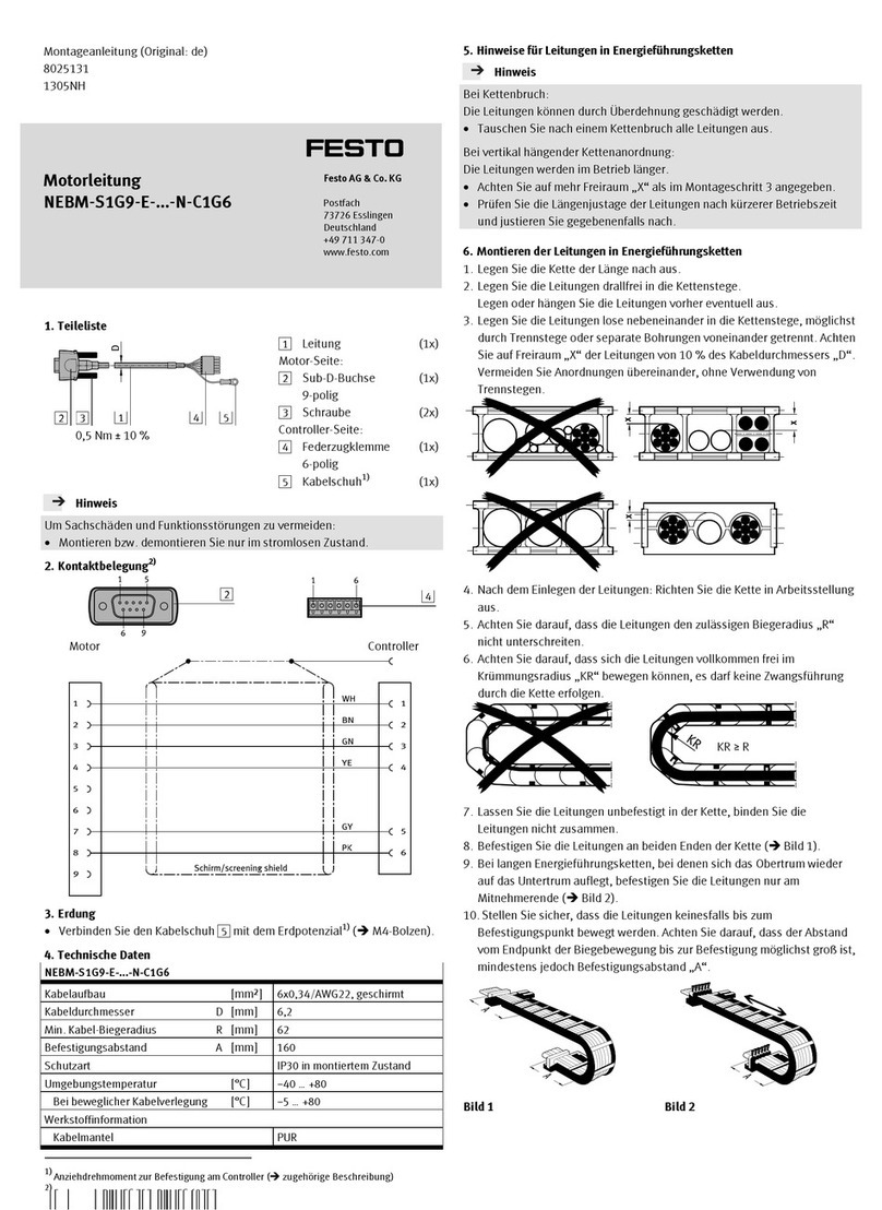
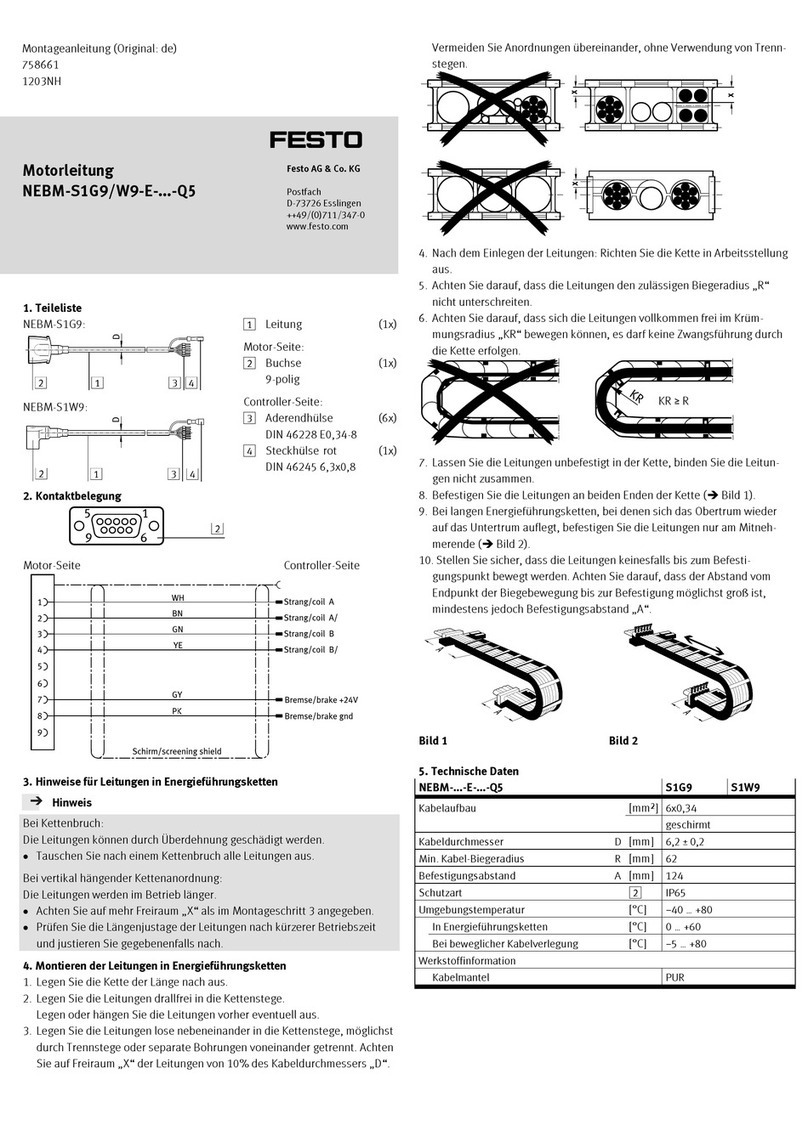
Festo HMVY-4 User manual

Festo

Festo HMVY-4 User manual

Festo QSP 18 Series User manual

Festo

Festo QSP 18 Series User manual

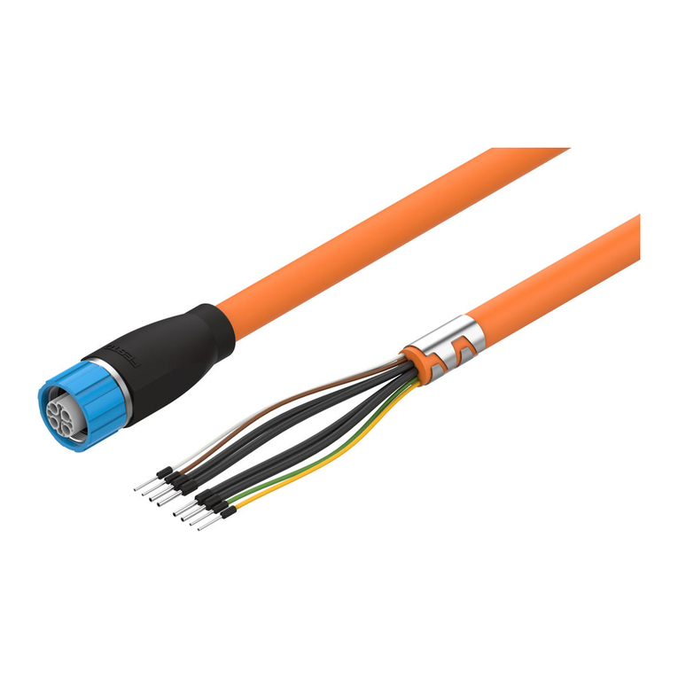
Festo NEBM-M23G12-E N-S1G9 Series User manual

Festo

Festo NEBM-M23G12-E N-S1G9 Series User manual

Festo ZBV-DGSL User manual

Festo

Festo ZBV-DGSL User manual

Festo NEBM-T1G8 Series Assembly instructions

Festo

Festo NEBM-T1G8 Series Assembly instructions

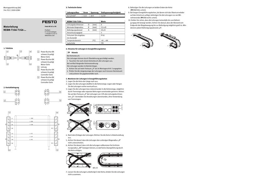
Festo NEBM-T1G6-T1G6 Series User manual

Festo

Festo NEBM-T1G6-T1G6 Series User manual

Festo NEBM-H6G4-Q13-LE4 Series User manual

Festo

Festo NEBM-H6G4-Q13-LE4 Series User manual

Festo NEBM-M12G8-E S1G9-V3 Series User manual

Festo

Festo NEBM-M12G8-E S1G9-V3 Series User manual

Festo NEBM-M23G6-E Series User manual

Festo

Festo NEBM-M23G6-E Series User manual

Festo NEBC-U3G5-ES N-S-U1G4 Series User manual

Festo

Festo NEBC-U3G5-ES N-S-U1G4 Series User manual

Festo YXCL-1 User manual

Festo

Festo YXCL-1 User manual

Festo FBS-SUB-9-GS-2x4POL-B User manual

Festo

Festo FBS-SUB-9-GS-2x4POL-B User manual

Festo NEBM-S1G9-E-***-N-C1G6 User manual

Festo

Festo NEBM-S1G9-E-***-N-C1G6 User manual

Festo NEBM-M12G8-E Q5 Series User manual

Festo

Festo NEBM-M12G8-E Q5 Series User manual

Festo NEBM-M12G12-RS N-S1G15 Series User manual

Festo

Festo NEBM-M12G12-RS N-S1G15 Series User manual

Festo NEBC-PPG6-E N-LE3-V Series User manual

Festo

Festo NEBC-PPG6-E N-LE3-V Series User manual

Festo NEBC-D12G4-E -R3G4-ET Series User manual

Festo

Festo NEBC-D12G4-E -R3G4-ET Series User manual

Festo NEBM-M40G8-E N-LE7 Series User manual

Festo

Festo NEBM-M40G8-E N-LE7 Series User manual

Festo VAVE-L1 Series User manual

Festo

Festo VAVE-L1 Series User manual

Festo FBS-RJ45-8-GS User manual

Festo

Festo FBS-RJ45-8-GS User manual

Festo MS6-9-AMV User manual

Festo

Festo MS6-9-AMV User manual

Festo NEBM-M12G12-RS N-M12G12H Series User manual

Festo

Festo NEBM-M12G12-RS N-M12G12H Series User manual

Festo NEBC-U7G10-ES N-S-U5G9 Series User manual

Festo

Festo NEBC-U7G10-ES N-S-U5G9 Series User manual

Festo NEBM-S1G9-E N-S1G9 Series User manual

Festo

Festo NEBM-S1G9-E N-S1G9 Series User manual

Popular Cables And Connectors manuals by other brands

Philips SWV2058W Specifications

Philips

Philips SWV2058W Specifications

TRENDnet TU3-SA - Quick installation guide

TRENDnet

TRENDnet TU3-SA - Quick installation guide

MADRIX ORION user manual

MADRIX

MADRIX ORION user manual

Paradyne 5030 installation instructions

Paradyne

Paradyne 5030 installation instructions

Panduit KMTRTH installation instructions

Panduit

Panduit KMTRTH installation instructions

Nordval PMPC01 instructions

Nordval

Nordval PMPC01 instructions

Staubli MA213-05 Assembly instructions

Staubli

Staubli MA213-05 Assembly instructions

Ophit HDMB2 user guide

Ophit

Ophit HDMB2 user guide

LEGRAND HT2202 manual

LEGRAND

LEGRAND HT2202 manual

NETVIO EX-HT2-401-10 quick start guide

NETVIO

NETVIO EX-HT2-401-10 quick start guide

HUBER+SUHNER QUICK-FIT 23 010 372 Assembly instruction

HUBER+SUHNER

HUBER+SUHNER QUICK-FIT 23 010 372 Assembly instruction

Gefen DisplayPort EXT-DPSB-100 user manual

Gefen

Gefen DisplayPort EXT-DPSB-100 user manual

3M 7620-S-2 instructions

3M

3M 7620-S-2 instructions

Gleason Reel 14", 16", 19" Direct Drive Electric Cable Reel... Installation and maintenance instructions

Gleason Reel

Gleason Reel 14", 16", 19" Direct Drive Electric Cable Reel... Installation and maintenance instructions

Thitronik XL 868 manual

Thitronik

Thitronik XL 868 manual

Tektronix Keithley 4200-RPC-2 Assembly instructions

Tektronix

Tektronix Keithley 4200-RPC-2 Assembly instructions

Olimpia splendid KIT B0620 Instructions for assembly

Olimpia splendid

Olimpia splendid KIT B0620 Instructions for assembly

Comar Systems ASR 100 Installation and quick reference guide

Comar Systems

Comar Systems ASR 100 Installation and quick reference guide

manuals.online logo
manuals.online logoBrands
  • About & Mission
  • Contact us
  • Privacy Policy
  • Terms and Conditions

Copyright 2025 Manuals.Online. All Rights Reserved.