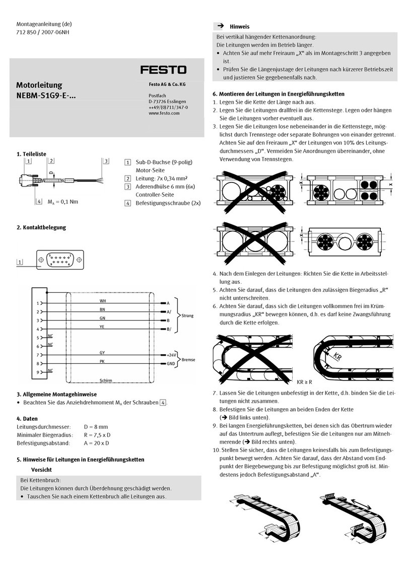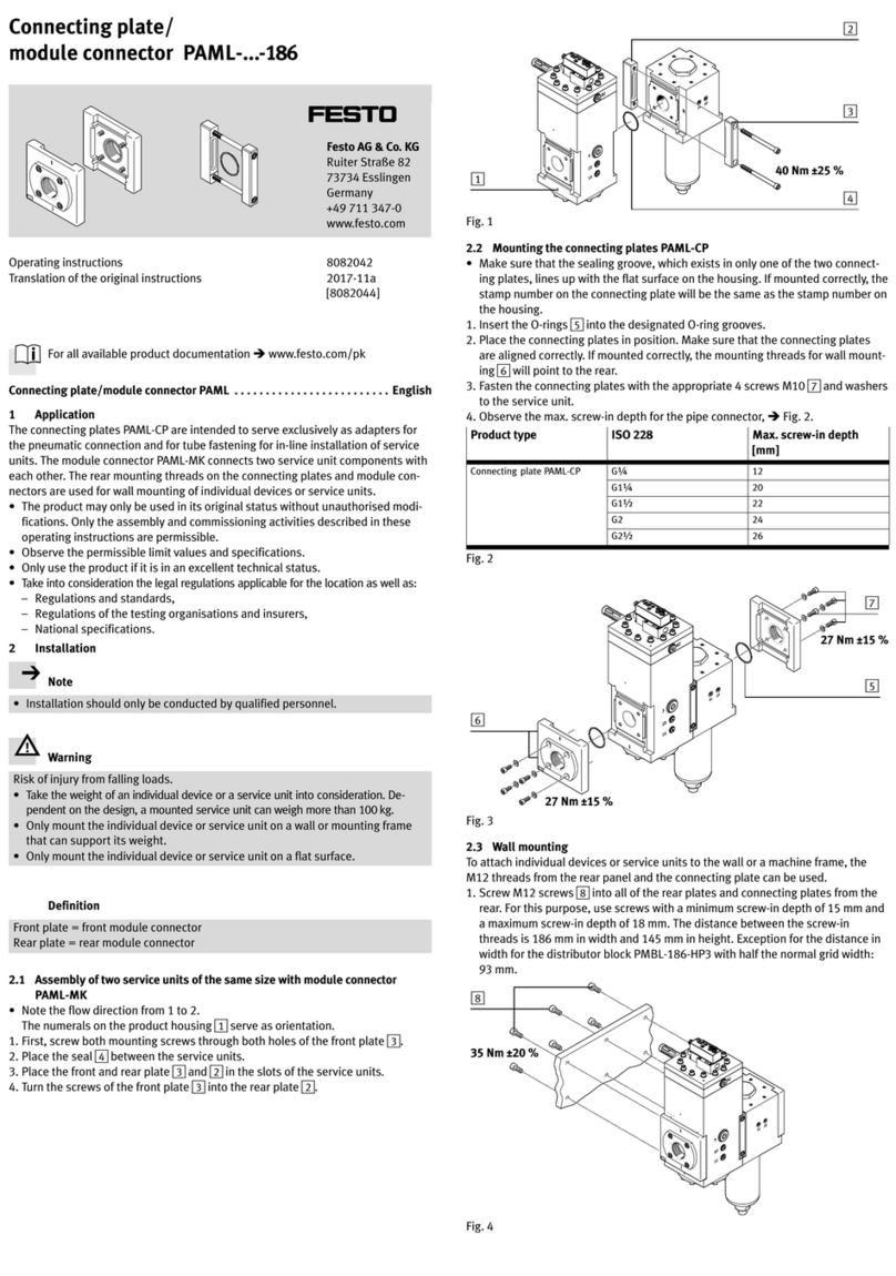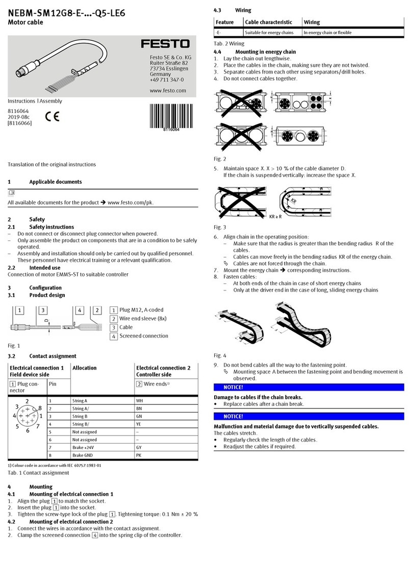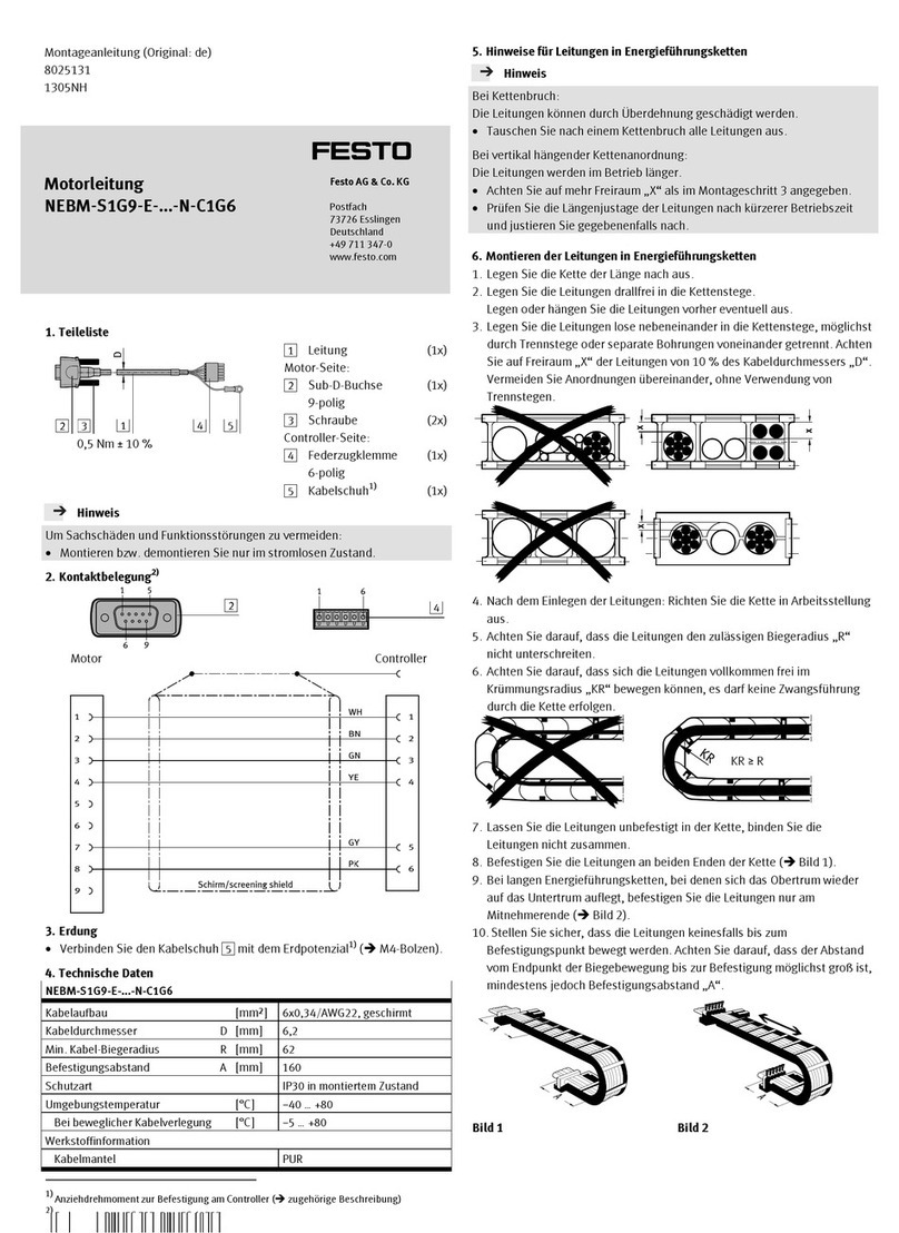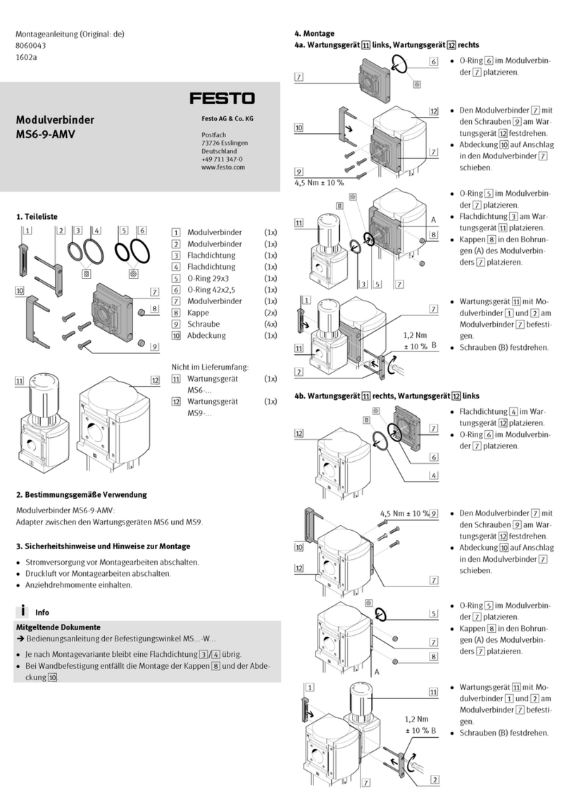
Mount the strain relief
Fig. 6
1. Check that the brass rings(K) of the cables(G) and (H) are seated correctly at
the strain relief(E).
2. Mount the strain relief(E) with the screw(F) on the brass rings(K). Tighten-
ing torque: 0.7Nm±30%
Attach the cover
Fig. 7
1. Place the cover(A) carefully on the connection box(B).
2. Ensure that there are no wires caught between the cover(A) and the connec-
tion box(B).
3. Tighten screws(C). Tightening torque: 1.2Nm±20%
4.2 Mounting, controller side
• Connect the plug connector3 to the matching socket on the controller until
it clicks into place.
4.3 Installation
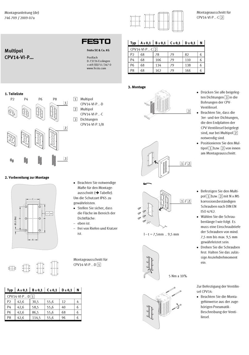
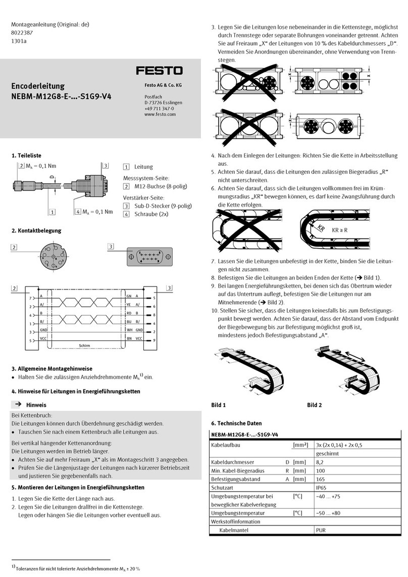
Mounting in energy chain
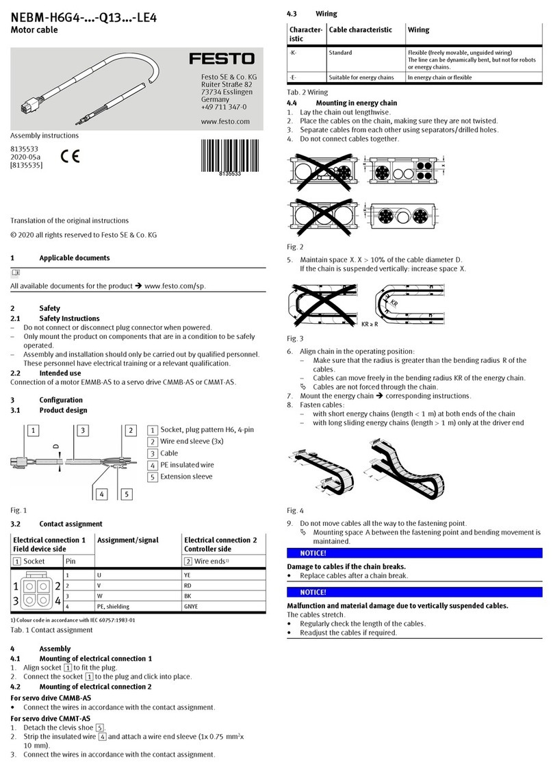
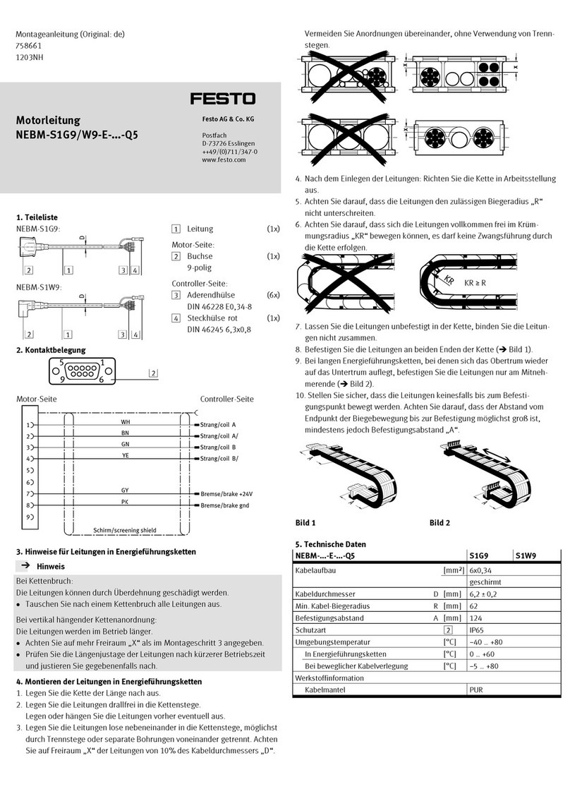
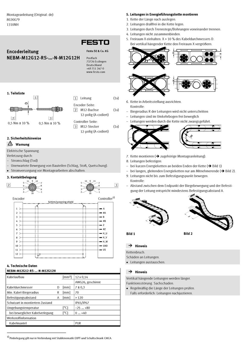
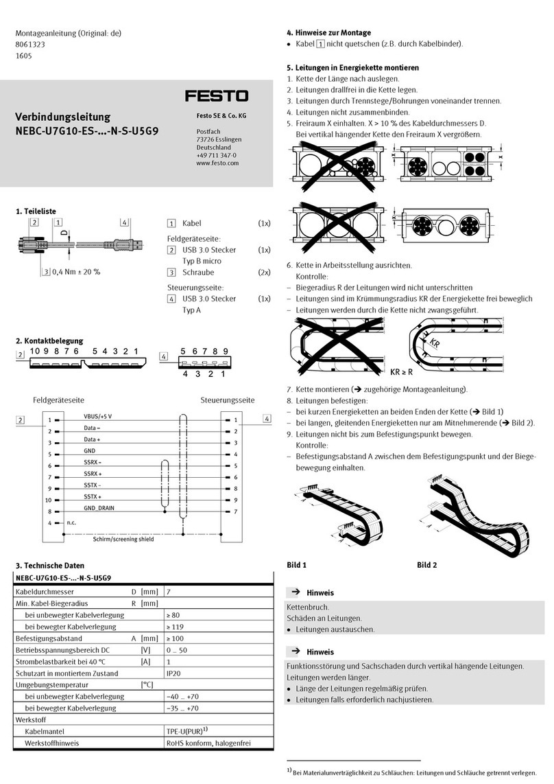
1. Lay the chain out lengthwise.
2. Place the cables in the chain, making sure they are not twisted.
3. Separate cables from each other using separators/drill holes.
4. Do not connect cables together.
Fig. 8
5. Maintain spaceX. X>10% of the cable diameterD.
If the chain is suspended vertically, increase the space X.
Fig. 9
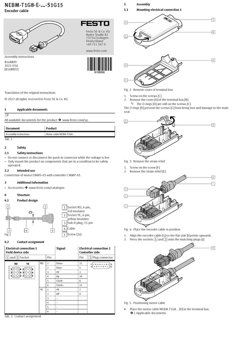
6. Align chain in the operating position:
– Make sure that the radius is greater than the bending radius R of the
cables.
– Cables can move freely in the bending radiusKR of the energy chain.
ÄCables are not forced through the chain.
7. Mount chain (ècorresponding instructions).
8. Fasten cables:
– At both ends of the chain in case of short energy chains
– Only at the driver end in the case of long, sliding energy chains
Fig. 10
9. Do not bend cables all the way to the fastening point.
ÄMounting spaceA between the fastening point and bending movement is
observed.
NOTICE!
Damage to cables if the chain breaks.
• Replace cables after a chain break.
NOTICE!
Malfunction and material damage due to vertically suspended cables.
The cables stretch.
• Regularly check the length of the cables.
• Readjust the cables if required.
5 Technical data
NEBMT1G8E...R3G8
Cable characteristic Suitable for energy chains
Cable composition [mm²] (4x0.14) + (4x0.34)
Shielding Shielded
Cable diameter D [mm] 6
Current rating
Current rating at 40°C [A] 3
Note on current rating at 40°C 2A for conductor cross-section 0.14mm2
Surge resistance [kV] 0.5
Operating voltage range AC/DC UB[V] 0…30
Degree of protection
Degree of protection IP65
Note on degree of protection In assembled state, IP20 for plug connector RJ45
Bending radius
Fixed cable installation R [mm] ³20
Flexible cable installation R [mm] ³75
Ambient temperature
Fixed cable installation [°C] –40…+80
Flexible cable installation [°C] –10…+80
Material
Cable sheath TPE-U(PUR)
Electrical connection1
Function Field device side
Connection type Socket
Connection technology ITT M3
Electrical connection2
Function Controller side
Connection type Plug connector
Connection technology RJ45
Tab. 2 Technical data
