Assembly instructions (translation: en)
8003791
1208NH
†‡
Motor cable
NEBM-M40G8-E-...-N-LE7
Festo AG & Co. KG
P.O. Box
D-73726 Esslingen
+49 (0)711 347 0
www.festo.com
1. Parts list
18209d_1
1Cable
Motor end:
2 M40 socket (8-pin)
Controller end:
3Wire end sleeve 8 mm
4Outside screen connection
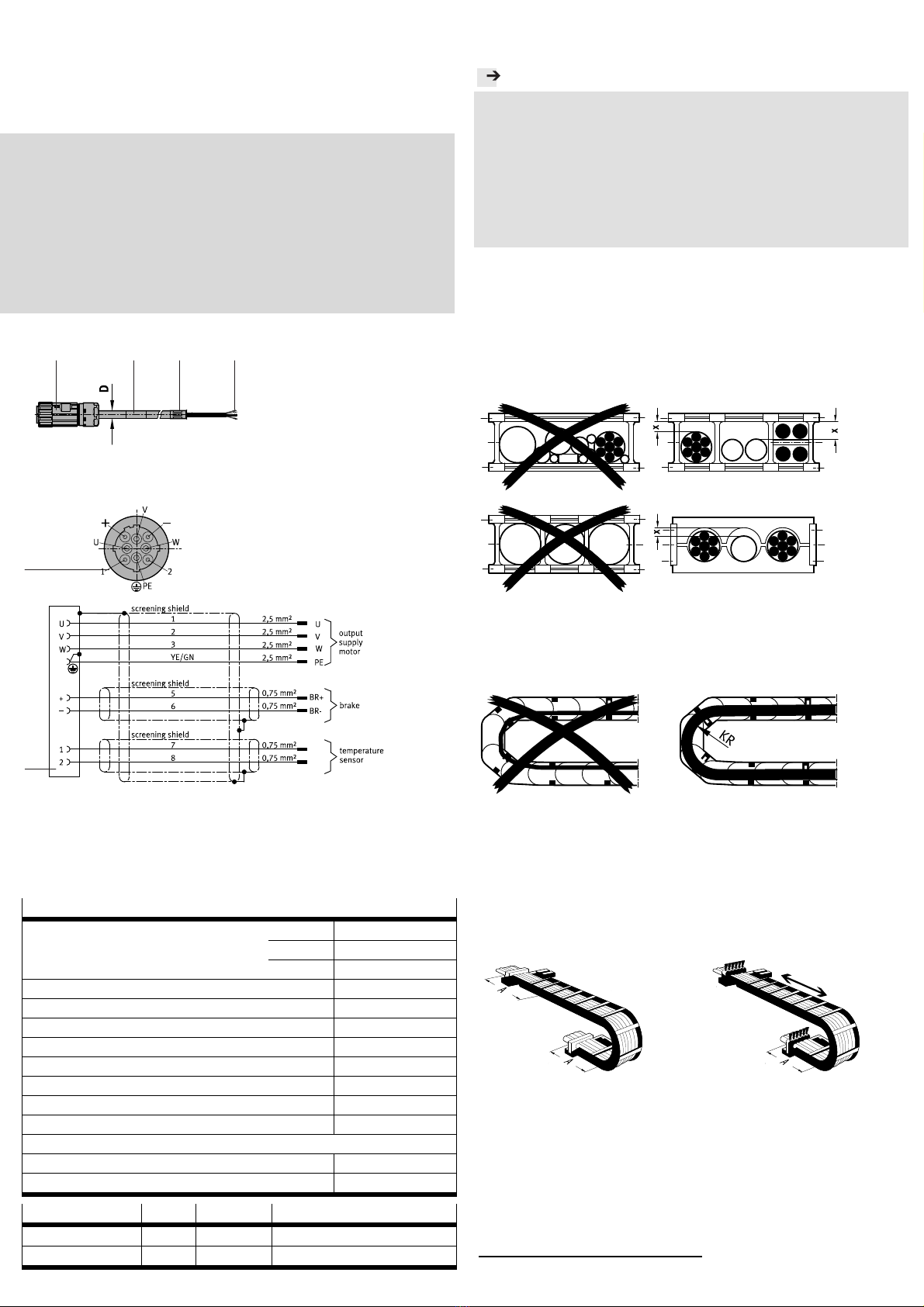
2. Pin allocation
18209d_2
18209d_4
3. General assembly instructions
Comply with the permissible tightening torque MA
1).
Clamp the external screen connection 4for the PE connection into the
spring clip of the controller.
4. Technical data
NEBM-M40G8-E-...-N-LE7
Cable composition [mm²] 2x (2x 0.75)
[mm²] 4x 2.5
Screened
Cable diameter D [mm] 14
Min. cable bending radius R [mm] 140
Mounting space A [mm] 280
Degree of contamination 3
Degree of protection (in mounted status) M40 IP 65
Ambient temperature [°C] -50 … +90
With flexible cable installation [°C] -40 … +90
Note on materials RoHS-compliant
Information on material
Cable sheath Polyurethane
Conforms to standard EN 61984
Cable composition Current Voltage Surge resistance
2x (2x 0.75 mm²) 12 A 300 V 2.5 kV
4x 2.5 mm² 26 A 630 V 4.0 kV
5. Instructions for cables in energy chains
Note
If there is a chain breakage:
The cables can be damaged due to overstretching.
Replace all the cables after a chain breakage.
With a vertical energy chain:
The cables will stretch during operation.
Ensure that there is more clearance “X” than specified in assembly step 3.
Check the length of the cables after a short operating period and adjust, if
necessary.
6. Mounting the cables in energy chains
1. Lay the chain out lengthwise.
2. Place the cables in the chain studs, making sure they are not twisted.
Lay out or hang the cables first, if necessary.
3. Lay the cables loose next to each other in the chain studs, if possible
separated from each other by separators or separate holes. Ensure the
clearance “X” of the cables is 10% of the cable diameter “D”. Avoid plac-
ing cables on top of each other if separators are not used.
7435d_3
4. After inserting the cables, adjust the chain into the operating position.
5. Make sure that the bending radius of the cables does not fall below the
permissible bending radius “R”.
6. Make sure that the cables can move freely in the bending radius “KR”; the
cables must not be forced through the chain.
7435d_4
7. Leave the cables loose in the chain, do not bind them together.
8. Fasten the cables to both ends of the chain (Fig. 1).
9. With long energy chains in which the upper run lies on the lower run, fas-
ten the cables only at the driver end (Fig. 2).
10. Make sure that the cables are on no account moved all the way to the
fastening point. Make sure the spacing between the end point of the
bending movement and the attachment is as large as possible, but at
least as large as mounting space “A”.
Fig. 1
7435d_2
Fig. 2
7435d_1
1)
1) Tolerances for non-toleranced tightening torques MA± 20%
M
= 1 Nm
KR ›R


