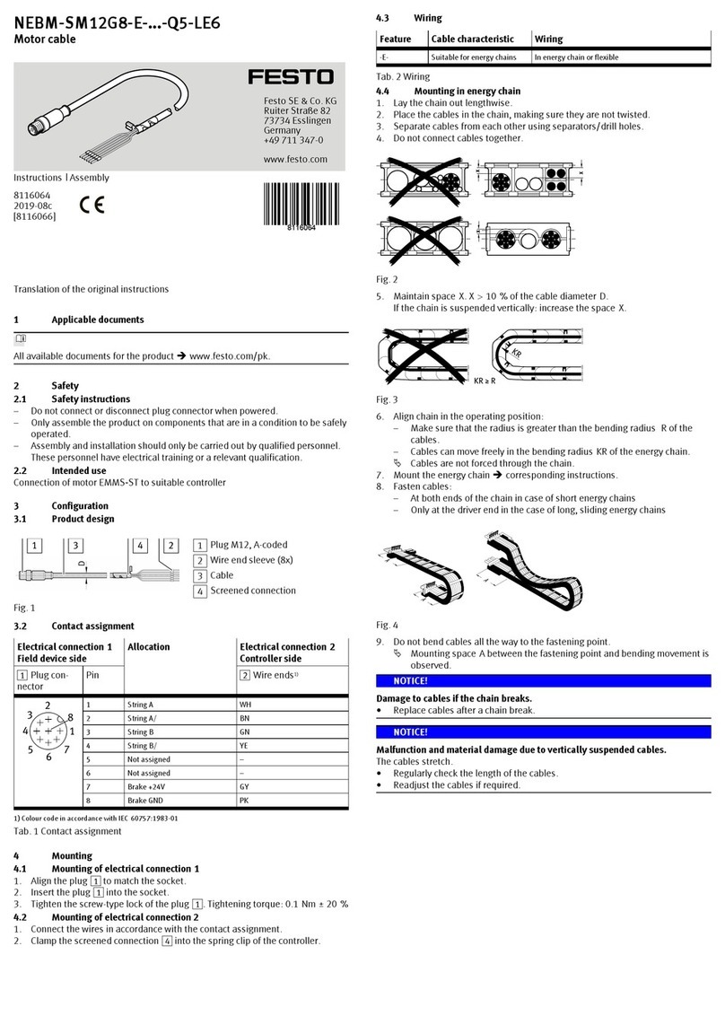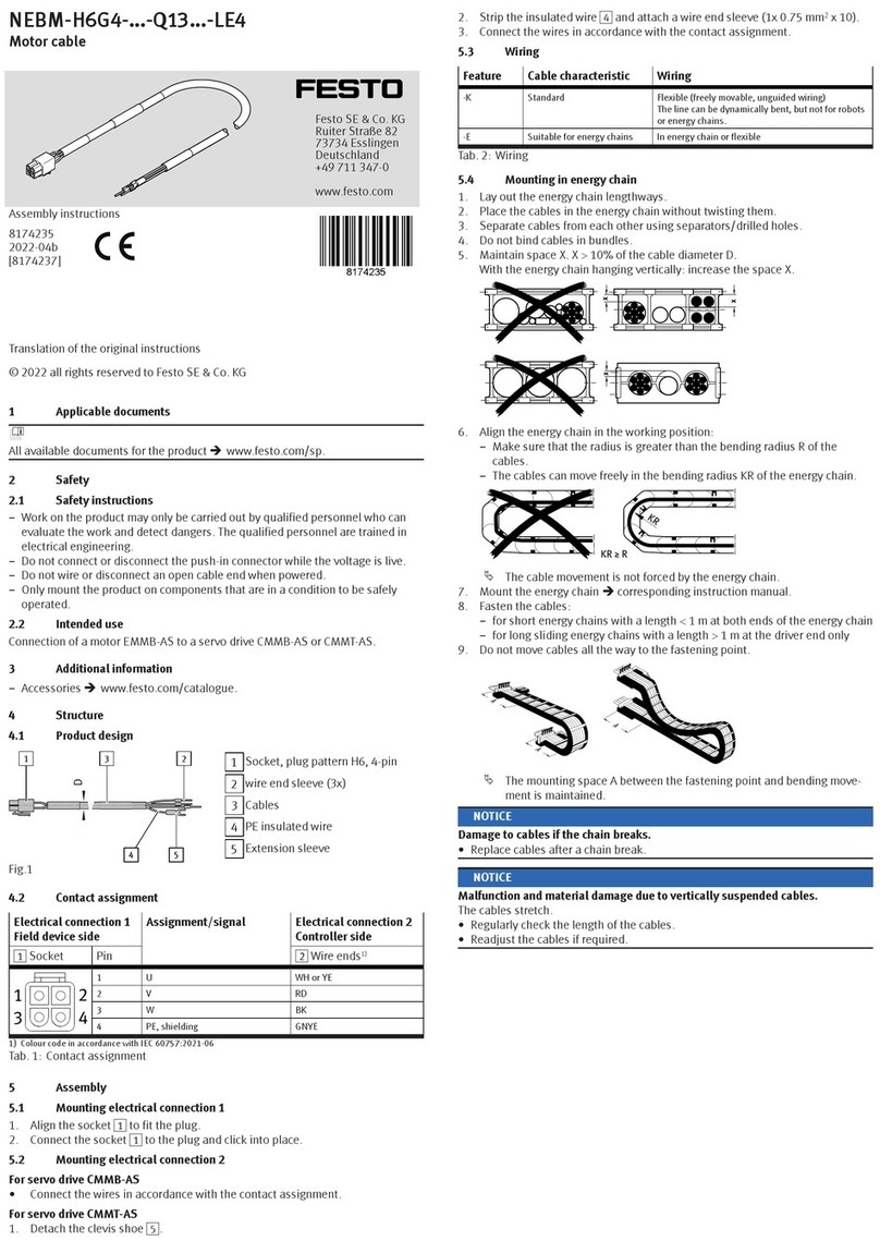
Assembly instructions (Original: de)
8044318
1504a
†‡
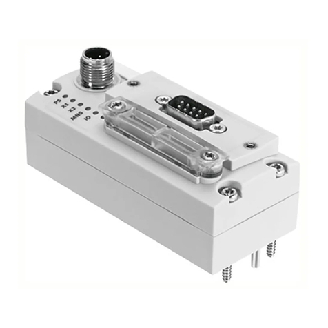
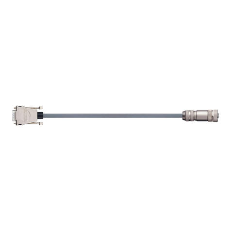
plug connector
FBS-RJ45-8-GS
Festo AG & Co. KG
Postfach
73726 Esslingen
Germany
+49 711 347-0
www.festo.com
4602d_10
1RJ45 plug connector
2 Cable insert aid
3Seal
4Housing
5M3x14 screw
6Pressure screw
7Clamping basket
8Seal
(1x)
(1x)
(1x)
(1x)
(2x)
(1x)
(1x)
(1x)
Not included in delivery:
(A) Crimping pliers for
RJ45
(B) Ethernet cable
(Section 6)
(1x)
(1x)
2. Intended use
FBS-RJ45-8-GS connector:
Connection of RJ45 interface to CPX-FEC or CPX-CEC for degree of protection
IP65/67 in vibration-resistant and shock-proof version.
3. Safety instructions and notes on mounting
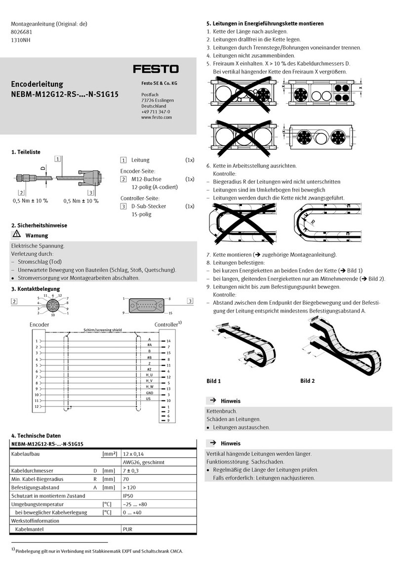
Information
Applicable document
Operating instructions for the crimpling pliers (A)
4. Pin allocation
Pin Signal Designation Core colours1
in accordance with
TIA-568-A2)
Core colours1)
in accordance with
TIA-568-B3)
1 TD + Transmitted data + GNWH ORWH
2 TD – Transmitted data – GN OR
3 RD + Received data + ORWH GNWH
4 n.c. Unused BU BU
5 n.c. Unused BUWH BUWH
6 RD – Received data – OR GN
7 n.c. Unused BNWH BNWH
8 n.c. Unused BN BN
1) Colour code in accordance with IEC 60757:1983-01
2) TIA/EIA-568-A:1995-10
3) TIA/EIA-568-B.2:2001-05
5. Mounting
4602d_11
Slide the following compo-
nents onto the cable (B):
–Pressure screw 6
–Clamping basket 7
–Gasket 8
–Housing 4
4602d_12
Strip 30 mm of insulation (C)
off cable sheath.
Cut braided screen (D) to
length of 8 mm and place on
cable sheath.
If available, remove.
–Cable filler
–Plastic braid
–Secondary braid
–Sheath film
4602d_13
Align cores in accordance
with pin allocation
(Section 4) beside one
another
4602d_14
Trim superfluous cores near
the insulation.
4602d_15
Trim ends of cores to length
obliquely (approx. 45°).
Note
Malfunction due to incorrect mounting.
Select pin allocation in accordance with the standard applicable to the
network (Section 3).
4602d_16
Insert cores into cable insert
guide 2in accordance with
pin allocation (Section 4).
4602d_17
slide recess on cable insert
guide 2until flush with ca-
ble sheath.
Check that cores are in the cor-
rect position.
Cut cores to length of 5 mm.
4602d_18
Pull cable insert guide 2
towards end of cable until
core tips protrude by 1 mm.
Information
On thicker, rigid cables, the cable sheath can be pressed flat using a blunt
tool to make it easier to insert in the RJ45 insert.
4602d_19
Slide cable (B) with cable in-
sert guide 2until firmly
home against stop in plug
connector 1.
Press in cable firmly.
All cores are located in the
correct position.
All cores are located on the
front of the plug connector.
Crimp connector 1(applicable document).
4602d_20
Slide plug connector 1up
against stop in housing 4.
Detent hook (E) snaps into
detect strip (F) on plug con-
nector 1.
Check: The rib (G) presses the
clip (H) against the connec-
tor 1.
4602d_21
Place gasket 3on hous-
ing 5.
–Press rubber lip (I) in as pro-
tector between detent
hook (E) and housing 4.
–Press rubber journal (K) into
the recesses (L).
4602d_22
Slide gasket 8into hous-
ing 4.
Slide clamping basket 7
into housing 4.
Tighten down pressure
screw 6. Observe the tight-
ening torque.
Tighten screws 5. Observe
the tightening torque.
6. Technical data
FBS-RJ45-8-GS
Permissible cable diameter [mm] 4 … 5.4
Ethernet cable specification
Type CAT.5
Individual wire diameter [mm] 0.89 … 0.99
AWG 24-26 fine wire
Degree of protection IP65, IP67
in mounted status
Ambient temperature [°C] −5 … +60
Material
Seals NBR
Housing PA-reinforced
Screws in Steel
