manuals.online logo
Brands
  1. Home
  2. •
  3. Brands
  4. •
  5. Festo
  6. •
  7. Cables And Connectors
  8. •
  9. Festo NEBM-T1G8-E -S1G15 Series User manual

Festo NEBM-T1G8-E -S1G15 Series User manual

NEBM-T1G8-E-...-S1G15
Encoder cable
Festo SE & Co. KG
Ruiter Straße 82
73734 Esslingen
Deutschland
+49 711 347-0
www.festo.com
Assembly instructions
8168890
2022-03d
[8168892]
Translation of the original instructions
© 2022 all rights reserved to Festo SE & Co. KG
1Applicable documents
All available documents for the product è www.festo.com/sp.
Document Product
Assembly instructions Motor cable NEBM-T1G8...
Tab. 1
2Safety
2.1 Safety instructions
–Do not connect or disconnect the push-in connector while the voltage is live.
–Only mount the product on components that are in a condition to be safely
operated.
2.2 Intended use
Connection of motor EMMS-AS with controller CMMP-AS.
3 Additional information
–Accessories è www.festo.com/catalogue.
4 Structure
4.1 Product design
1
2
3
4 5
Fig.1
1
Socket RD, 6-pin,
red insulator
2
Socket YE, 6-pin,
yellow insulator
3
Sub-D plug, 15-pin
4
Cable
5
Screw (2x)
4.2 Contact assignment
Electrical connection 1
Field device side
Signal Electrical connection 2
Controller side
1 and 2 Socket Pin Pin 3 Plug connector
RD 1 Data+ 12
2 Data– 5
3 0V 3
4 Up 10
5 Clock– 6
6 Clock+ 13
YE 1 0V 2
2 UP 9
3 –
4 –
5 –
6 –
Tab. 2: Contact assignment
5 Assembly
5.1 Mounting electrical connection 1
A
C
C
B
A
C
D
Fig. 2: Remove cover of terminal box
1. Screw on the screws [C].
2. Remove the cover [A] of the terminal box [B].
ÄThe O-rings [D] are still on the screws [C].
The O-rings [D] prevent the screws [C] from being lost and damage to the main
seal.
F
E
Fig. 3: Remove the strain relief
1. Screw on the screw [F].
2. Remove the strain relief [E].
1
2
G
I
J
Fig. 4: Place the encoder cable in position
1. Align the encoder cable [G] so the flat side [I] points upwards.
2. Press the sockets 1 and 2 onto the matching plugs [J].
H
Fig. 5: Positioning motor cable
• Place the motor cable NEBM-T1G8... [H] in the terminal box
è 1 Applicable documents.
6.
8.
E
F
K
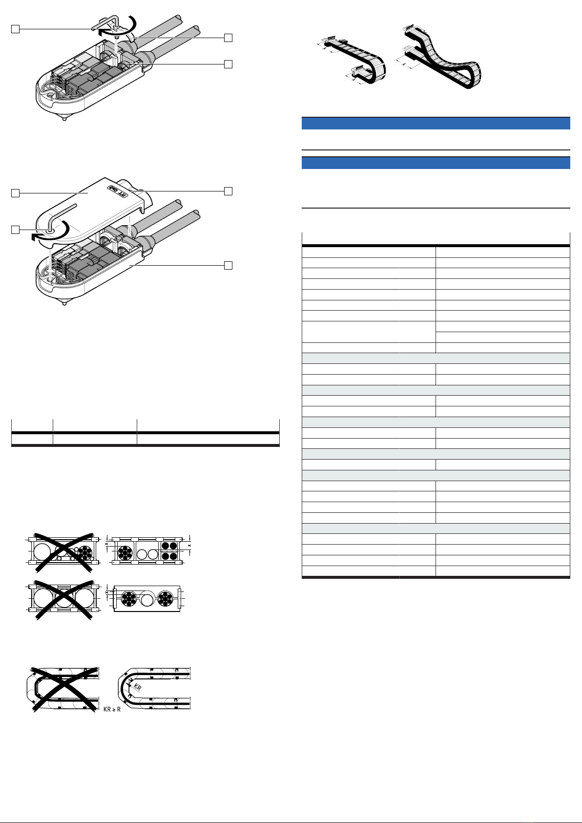
Fig. 6: Fastening strain relief
1. Check that the brass rings [K] of the cables [G] and [H] are correctly seated at
the position of the strain relief [E].
2. Fasten the strain relief [E] with the screw [F] to the brass rings [K]. Tightening
torque: 0.7 Nm ± 30%
C
C
A
B
Fig. 7: Fasten the cover of the terminal box
1. Carefully position the cover [A] on the terminal box [B].
ÄThere are no wires pinched between the cover [A] and the terminal
box [B].
2. Tighten the screws [C]. Tightening torque: 1.2 Nm ± 20%
5.2 Mounting electrical connection 2
1. Align the plug 3 to match the socket.
2. Insert the plug 3 into the socket.
3. Tighten the screws 5. Tightening torque: 0.1 Nm ± 20%
5.3 Wiring
Feature Cable characteristic Wiring
-E Suitable for energy chains in energy chain or flexible
Tab. 3: Wiring
5.4 Mounting in energy chain
1. Lay out the energy chain lengthways.
2. Place the cables in the energy chain without twisting them.
3. Separate cables from each other using separators/drilled holes.
4. Do not bind cables in bundles.
5. Maintain space X. X > 10% of the cable diameter D.
With the energy chain hanging vertically: increase the space X.
Align the energy chain in the working position:
–Make sure that the radius is greater than the bending radius R of the
cables.
–The cables can move freely in the bending radius KR of the energy chain.
ÄThe cable movement is not forced by the energy chain.
7. Mount the energy chain è corresponding instruction manual.
Fasten the cables:
–for short energy chains with a length < 1 m at both ends of the energy chain
–for long sliding energy chains with a length > 1 m at the driver end only
9. Do not move cables all the way to the fastening point.
ÄThe mounting space A between the fastening point and bending move-
ment is maintained.
NOTICE
Damage to cables if the chain breaks.
• Replace cables after a chain break.
NOTICE
Malfunction and material damage due to vertically suspended cables.
The cables stretch.
• Regularly check the length of the cables.
•Readjust the cables if required.
6Technical data
NEBM-T1G8-E-...-S1G15
Certificates, declaration of conformity è www.festo.com/sp
Cable characteristic Suitable for energy chains
Cable function Encoder cable
Cable composition [mm²] 1x4x0.15 + 4x1x0.34
Shielding Shielded
Cable diameter D [mm] 6
Mounting space A [mm] ³ 120
Current rating at 40 °C [A] 3 for conductor cross-section 0.34 mm2
2 for conductor cross-section 0.15 mm2
Surge resistance [kV] 0.5
Operating voltage range
AC UB[V] 0 … 30
DC UB[V] 0 … 30
Bending radius
Fixed cable installation R [mm] ³ 20
Flexible cable installation R [mm] ³ 48
Ambient temperature
Fixed cable installation [°C] –40 … +80
Flexible cable installation [°C] –10 … +80
Material
Cable sheath TPE-U(PUR)
Electrical connection 1
Function Field device side
Connection type Socket
Connection technology ITT M3
Degree of protection IP65 In assembled state
Electrical connection 2
Function Controller side
Connection type Plug connector
Connection technology Sub-D
Degree of protection IP30 In assembled state
Tab. 4: Technical data

Other Festo Cables And Connectors manuals

Festo NEBM-H6G4-Q13-LE4 Series User manual

Festo

Festo NEBM-H6G4-Q13-LE4 Series User manual

Festo MS9-12-ARMV User manual

Festo

Festo MS9-12-ARMV User manual

Festo NEBM-M23G12-E N-S1G9 Series User manual

Festo

Festo NEBM-M23G12-E N-S1G9 Series User manual

Festo NEBM-M12G8-E S1G15 Series Assembly instructions

Festo

Festo NEBM-M12G8-E S1G15 Series Assembly instructions

Festo NEBC-S1G9-K N-S-S1G9 Series User manual

Festo

Festo NEBC-S1G9-K N-S-S1G9 Series User manual

Festo NEBM-M12W8-E Series User manual

Festo

Festo NEBM-M12W8-E Series User manual

Festo NEBM-M12W8-E Series User manual

Festo

Festo NEBM-M12W8-E Series User manual

Festo NEBM-S1G9-E N-S1G9 Series User manual

Festo

Festo NEBM-S1G9-E N-S1G9 Series User manual

Festo NEBM-M23G6-E Series User manual

Festo

Festo NEBM-M23G6-E Series User manual

Festo NEBM-L2G16-EH-Series-Q6N-LE8 User manual

Festo

Festo NEBM-L2G16-EH-Series-Q6N-LE8 User manual

Festo NEBM-M12G12-RS N-M12G12H Series User manual

Festo

Festo NEBM-M12G12-RS N-M12G12H Series User manual

Festo NEBM-S1G9-E Series User manual

Festo

Festo NEBM-S1G9-E Series User manual

Festo NEBM-S1G9-E-***-N-C1G6 User manual

Festo

Festo NEBM-S1G9-E-***-N-C1G6 User manual

Festo CTEU-AS Operating and installation instructions

Festo

Festo CTEU-AS Operating and installation instructions

Festo ZBV-DGSL User manual

Festo

Festo ZBV-DGSL User manual

Festo NEBM-T1G8-E R3G8 Series Assembly instructions

Festo

Festo NEBM-T1G8-E R3G8 Series Assembly instructions

Festo NEBM-M12G8-E S1G9-V4 Series User manual

Festo

Festo NEBM-M12G8-E S1G9-V4 Series User manual

Festo CPV14-VI-P Series User manual

Festo

Festo CPV14-VI-P Series User manual

Festo VAVE-L1 Series User manual

Festo

Festo VAVE-L1 Series User manual

Festo KMYZ-9-24-AD-0,2 Series User manual

Festo

Festo KMYZ-9-24-AD-0,2 Series User manual

Festo NEBC-D12G4-E -R3G4-ET Series User manual

Festo

Festo NEBC-D12G4-E -R3G4-ET Series User manual

Festo KMP3 Series User manual

Festo

Festo KMP3 Series User manual

Festo NEBM-H6G4 Q13 LE4 Series User manual

Festo

Festo NEBM-H6G4 Q13 LE4 Series User manual

Festo HMVY-4 User manual

Festo

Festo HMVY-4 User manual

Popular Cables And Connectors manuals by other brands

ULTRA TEC CapTel installation guide

ULTRA TEC

ULTRA TEC CapTel installation guide

Clear-Com FreeSpeak II user guide

Clear-Com

Clear-Com FreeSpeak II user guide

Tripp Lite N518-15M Specification sheet

Tripp Lite

Tripp Lite N518-15M Specification sheet

IPEX 20613-0 E-0 Series instruction manual

IPEX

IPEX 20613-0 E-0 Series instruction manual

Inakustik AC-1502 MKII Operation manual

Inakustik

Inakustik AC-1502 MKII Operation manual

Tripp Lite P131-06N-2VA-U owner's manual

Tripp Lite

Tripp Lite P131-06N-2VA-U owner's manual

Pro-Star PS-90XD user manual

Pro-Star

Pro-Star PS-90XD user manual

Tripp Lite N506-02M Specification sheet

Tripp Lite

Tripp Lite N506-02M Specification sheet

DekoLight 710036 Product notes

DekoLight

DekoLight 710036 Product notes

Black Box PC to Printer Cables Specifications

Black Box

Black Box PC to Printer Cables Specifications

Tripp Lite U206-006-R user manual

Tripp Lite

Tripp Lite U206-006-R user manual

IPEX ISH Series instruction manual

IPEX

IPEX ISH Series instruction manual

Rocket Fish RF-G1182 Quick setup guide

Rocket Fish

Rocket Fish RF-G1182 Quick setup guide

M-Elec LOX quick start guide

M-Elec

M-Elec LOX quick start guide

Tripp Lite P050-008 Specification sheet

Tripp Lite

Tripp Lite P050-008 Specification sheet

NewGarden LED Tube Instructions for use

NewGarden

NewGarden LED Tube Instructions for use

Tripp Lite P502-010-RA Specification sheet

Tripp Lite

Tripp Lite P502-010-RA Specification sheet

ADTRAN 1184544P2 quick start guide

ADTRAN

ADTRAN 1184544P2 quick start guide

manuals.online logo
manuals.online logoBrands
  • About & Mission
  • Contact us
  • Privacy Policy
  • Terms and Conditions

Copyright 2025 Manuals.Online. All Rights Reserved.