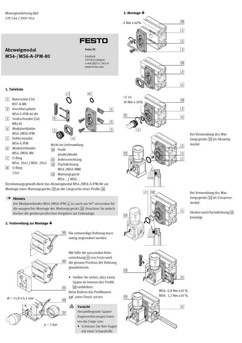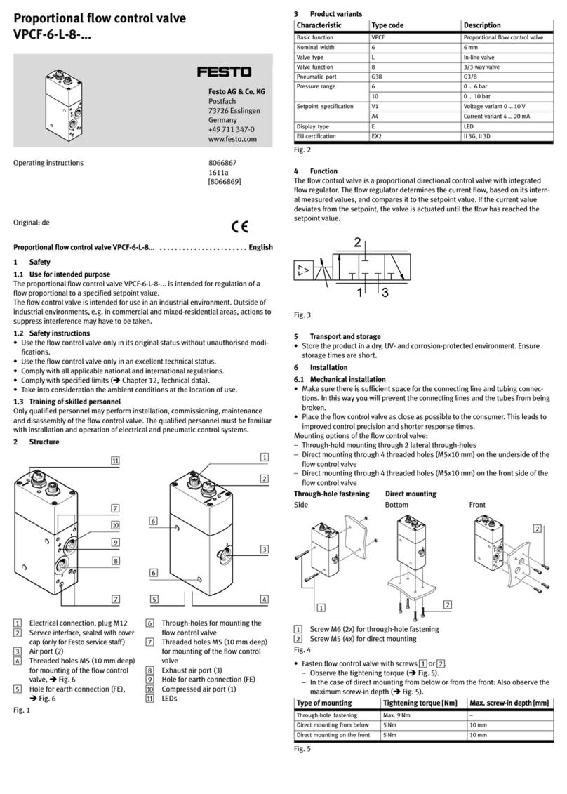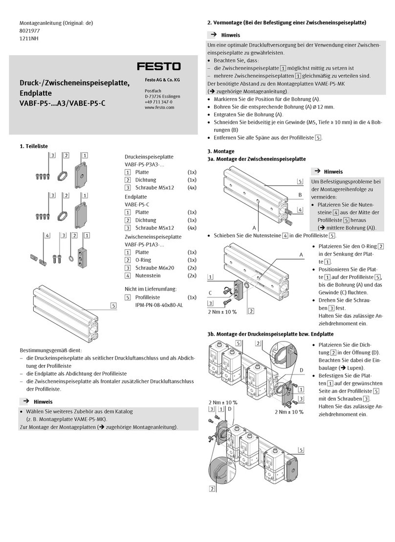
The filter can be inspected visually through the transparent filter cover.
Cleaning the air filter:
1
2
Fig. 16 Removing/installing the filter
1. Vent the vacuum suction nozzle.
2. Carefully pull out the slide 1of the filter 2up to the first detent. The slide 1
must stay in this position on the filter.
3. Pull the filter out.
(Use a screwdriver to help to bring out the filter, if necessary)
4. Clean the filter 2with cleaner’s solvent, for example.
5. Push the filter 2into its housing using the slide 1.
6. Push in the slide 1.
9 Fault clearance
Malfunction Possible cause Remedy
Workpiece does not re
lease from the suction
cup
A vacuum has built up when lift
ing large suction cups quickly
Increase the intensity of the eject
or pulse
Lift the suction cup more slowly
from the workpiece
Actively set the ejector pulse
when lifting the suction cup
Workpiece does not re
lease from the suction
cup
Tubing used between the suc
tion cup and vacuum suction
nozzle is wrongly sized (tube is
too long and/or tube internal
diameter is too small)
Replace hose, for hose require
ments èChapter 5.2
Flow control screw is closed Open the flow control screw
No LED display for switch
ing inputs
Supply voltage not applied or no
permitted operating voltage
Switch on supply voltage / main
tain permitted operating voltage
range
Connections swapped (incorrect
polarity)
Wire the device in accordance
with the connection arrange
ment
No control signal Check the control system
Device defective Replace the device
No LED display for switch
ing output
Pressure failure Eliminate pressure failure
Vacuum suction nozzle operated
with impermissible medium
Replace the vacuum suction
nozzle and operate only with
compressed air
LED display or switching
output does not react in
accordance with the set
tings made
Short circuit or overload at the
output
Eliminate short circuit/overload
Incorrect switching point (e.g. at
0 bar)
Repeat teach procedure
(èChapter 6.2)
Device defective Replace the device
Fig. 17 Fault clearance
10 Disassembly
1. Switch off the following sources of energy before dismantling:
– operating voltage
– compressed air.
2. Disconnect the electrical and pneumatic connections to the vacuum suction
nozzle.
3. Remove the vacuum suction nozzle.
11 Accessories
Designation OVEM-05 OVEM-07/10 OVEM-14/-20
Connecting cable M12x1, 5-pin, 2.5 m NEBU-M12G5-K-2.5-LE5
Connecting cable M12x1, 5-pin, 5 m NEBU-M12G5-K-5-LE5
H-rail mounting OABM-H
Mounting bracket HRM-1
Silencer extension – UOMS-¼ UOMS-¼
Common supply manifold OABM-P-4
OABM-P-6
OABM-P-8
Blanking plug OASC-G1-P
Fig. 18 Accessories
12 Technical data
OVEM -05 -07/-10 -14/-20
Operating pressure [bar] 2 … 8
QS/GN/PL-…-1P/1N: 2 … 6
Operating medium Compressed air to ISO 8573-1:2010 [7:4:4]
Note on the operating medium Lubricated operation not possible
Ambient temperature [°C] 0 … 50
Temperature of medium [°C] 0 … 50
Degree of contamination 3
Relative air humidity [%] 5 … 85
Nominal operating voltage [V DC] 24 ±15 %
Max. current consumption [mA] -1P, -1N: 180
Without vacuum sensor: 30
Idle current1) [mA] 80
Coil characteristics 24 V DC [W] Low-current phase: 0.3
High-current phase: 2.55
Time until current reduction [ms] 80
Ready-state delay [ms] 500
Switching output
– Max. output current [mA] 100
– Voltage drop [V] 1.5
– Capacitive load maximum DC [nF] 100
Dead time [ms] 12 22 35
Protective functions
– inductive protective circuit Adapted to MZ, MY, ME coils
– Protection against short circuit Yes
– Overload protection Yes
Protection against incorrect polarity For all electrical connections
Insulation voltage [V] 50
Surge resistance [kV] 0.8
Degree of protection IP65
Protection class 3
Resistance to interference See declaration of conformity (www.festo.com)2)
Emitted interference See declaration of conformity (www.festo.com)2)
Vibration resistance in accordance with IEC/EN 60068 part 2-6:
0.35 mm travel at 10 … 60 Hz,
5 g acceleration at 60 ... 150 Hz
Resistance to shocks in accordance with IEC/EN 60068 part 2-27:
30 g acceleration with 11 ms duration (half-sine)
Max. permitted signal line length [m] 30
Overload pressure at vacuum port [bar] 1P/1N: 5
Without vacuum sensor: 10
Pressure measuring range4) [bar] –1 … 0
Repetition accuracy of switching
value3)4)
[% FS] Max. ±0.3
Temperature coefficient3)4) [% FS/K] ±0.05
Threshold value setting range4) [bar] –1 … 0
Hysteresis, permanently set3)4) [mbar] 20
1) Both solenoid valves are actuated
2) The product is intended for use in industrial environments. Measures for interference suppression may
need to be implemented in residential areas.
3) % FS = % of the final value in the measuring range (full-scale)
4) Technical feature only relevant for types with vacuum sensor
Fig. 19 Technical data
12.1 Factory setting
OVEM-...
Out Switching point (SP) –0.4 bar
(Fixed hysteresis (HYS) 20 mbar
Fig. 20 Factory setting
