manuals.online logo
Brands
  1. Home
  2. •
  3. Brands
  4. •
  5. Festo
  6. •
  7. Control Unit
  8. •
  9. Festo MS9-SV-10V24P User manual

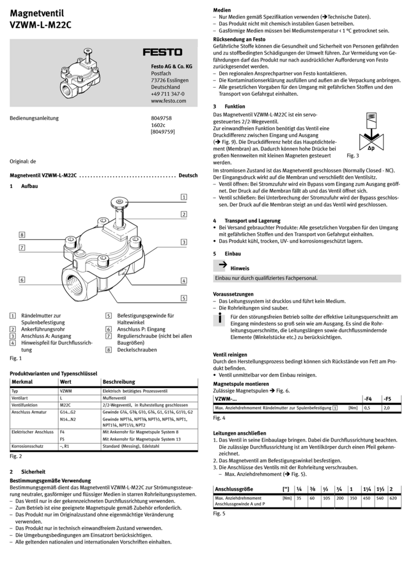
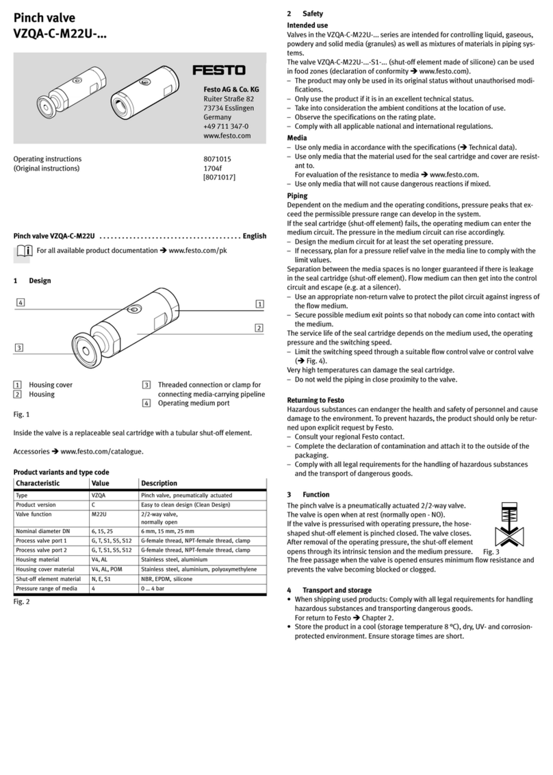
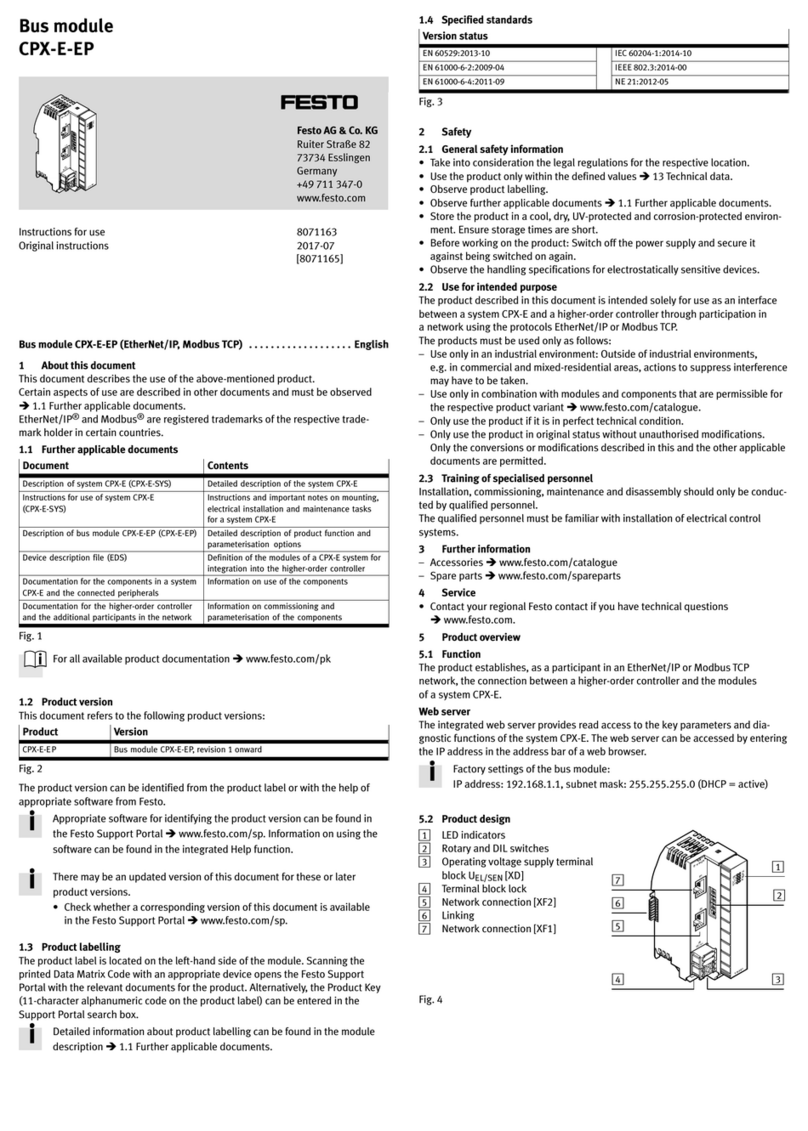
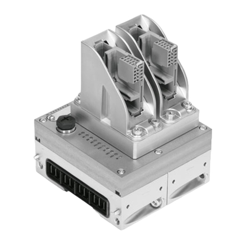
Festo MS9-SV-10V24P User manual

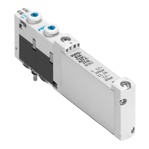
Soft-start/quick exhaust
valve MS9-SV-...-C
Festo AG & Co. KG
Postfach
D-73726 Esslingen
+49 711 347 0
www.festo.com
Operating instructions 8004379
1205NH
Original: de
Soft-start/quick exhaust valve MS9-SV-...-C English........................
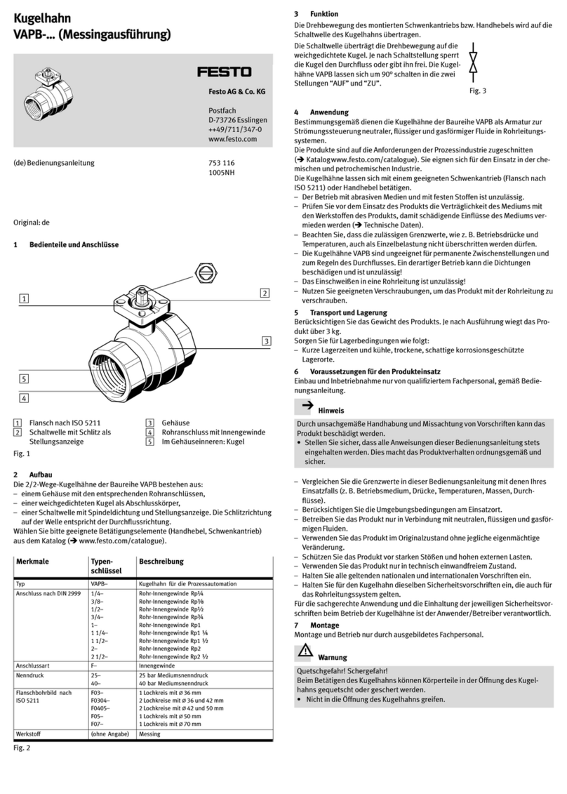
1 Product description
1.1 Operating elements and connections
1
2
3
4
5
6
7
8
9
1Pilot solenoid valve
2Manual override at the soft-start/
quick exhaust valve
3Pneumatic port 1 (compressed air
inlet)
4Pneumatic port 3 (exhaust)
5Silencer
6Manual override at the pilot solen-
oid valve
7Flow control screw for setting the
filling time
8Adjusting screw for setting the
pressure switching point
9Pneumatic port 2 (compressed air
outlet)
Fig. 1 Control sections and connections
1.2 Characteristics
Characteristics Type Specification
Series MS Standard service unit
Size 9Grid dimension 90 mm
Function -SV Soft-start/quick exhaust valve
Connection size -3/4 Thread G¾
-1 Thread G1
-AGD Connecting plate G½
-AGE Connecting plate G¾
-AGF Connecting plate G1
-AGG Connecting plate G1¼
-AGH Connecting plate G1½
-N3/4 Thread N¾
-N1 Thread N1
-AQR Connecting plate N½
-AQS Connecting plate N¾
-AQT Connecting plate N1
-AQU Connecting plate N1¼
-AQV Connecting plate N1½
-G Module without connecting thread, without connecting
plate
-NG Module without connecting thread, without connecting
plate (connection 3 in NPT)
Performance level -C in accordance with EN ISO 13849-1
Supply voltage -V24 24 V DC (connection arrangement in accordance with
EN 175301)
-10V24P 24 V DC (M12 in accordance with IEC 61076-2-101)
-V110 110 V AC (connection arrangement in accordance with
EN 175301)
-V230 230 V AC (connection arrangement in accordance with
EN 175301)
Options -S Silencer
Tamper protection -MH Cover – only manual override (MO)
-MK Cover – adjusting screws pressure switching point (PSP)
and main throttle (MT), manual override (MO)
Fig. 2 Overview of variants
2 Function and application
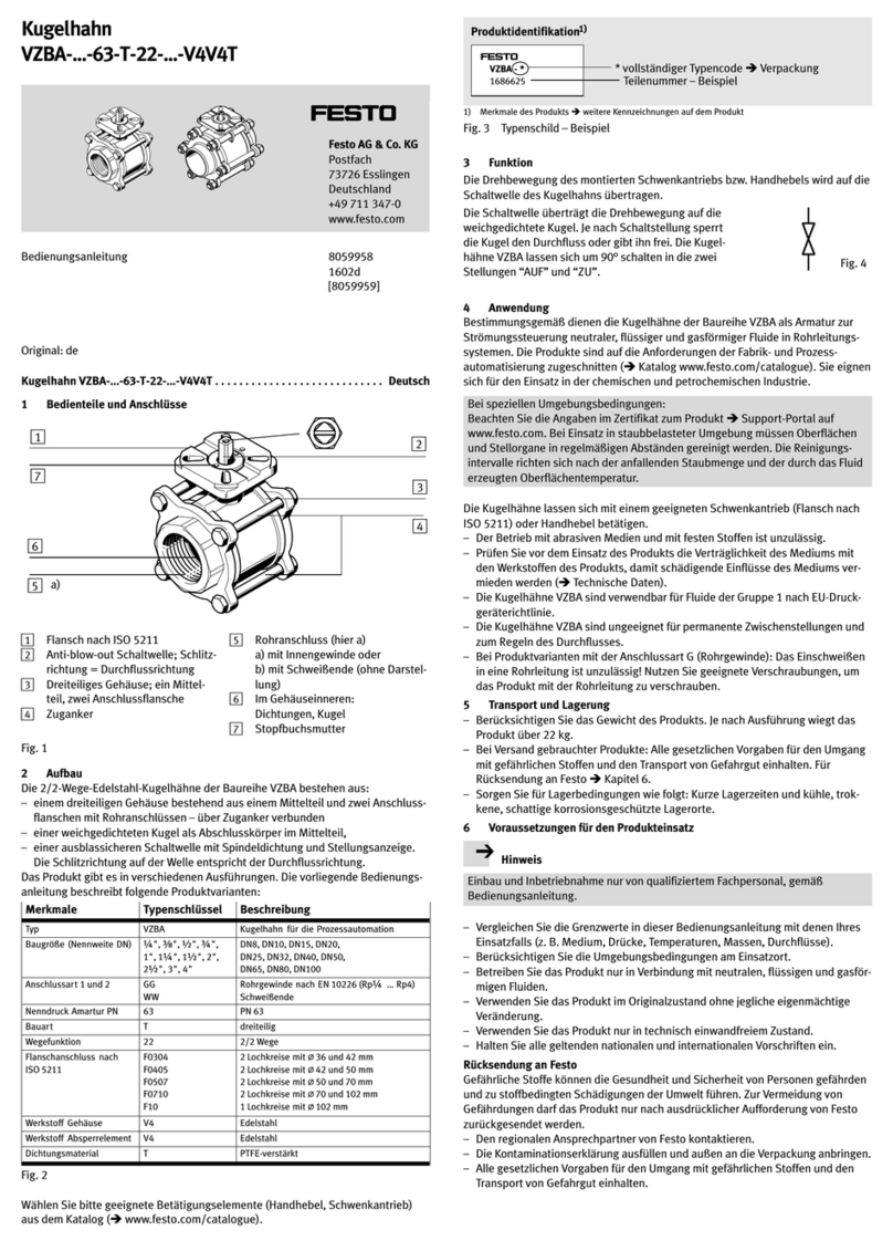
The electro-pneumatic soft-start/quick exhaust valve MS9-SV-...-C is intended for
fast pressure reducing as well as pressure reducing in pneumatic piping systems
and terminals in industry.
Symbol Function
Soft-start/quick exhaust valve, electro-pneumatically
actuated
Fig. 3 Circuit symbol of the functions
The product is intended for installation in machines or automated systems and
maybeusedonlyinthefollowingways:
– in industrial applications
– within the limits of the product defined through the technical data
(13 Technical data)
– in its original status, without unauthorised modifications
– in perfect technical condition
2.1 Foreseeable misuse
Foreseeable misuse includes:
– use outdoors
– use as a press safety valve
– use in the non-industrial area/residential area
– use outside the limits of the product defined in the technical data
– unauthorised modifications
– use in reversible operation (reversal of supply and exhaust air)
– “low demand mode” in accordance with EN 61511 or vacuum operation
Note
In the event of damage caused by unauthorised manipulation or use other than
that intended, the guarantee is invalidated and the manufacturer is not liable for
damages.
3 Requirements for product use
• Make these operating instructions available to the design engineer and installer
of the machine or system in which this product will be used.
• Keep these operating instructions during the entire product life cycle.
• Observe the rules/information of the trade association, the VDE specifications
and relevant national regulations at the location of use.
3.1 Technical requirements
General conditions for the correct and safe use of the product, which must be
observed at all times:
• Maintain the specified limits (e.g. for pressures, temperatures and electric
voltages).
• Make sure there is a supply of correctly prepared compressed air in accordance
with the specifications on the medium.
• Before mounting, remove particles in the supply lines through appropriate
measures. In this way, you protect the product from premature failure and high-
er wear.
• Pressurize your entire system slowly. This allows avoidance of abrupt move-
ments.
• Observe the warnings and instructions in these operating instructions.
• Use the product in its original state, without any unauthorised product modifica-
tions.
3.2 Qualification of trained personnel
Installation, mounting, commissioning, maintenance, repair and removal from
operation may only be performed by qualified personnel with knowledge and ex-
perience with electrical and pneumatic control technology.
3.3 Range of application and certifications
The products MS9-SV-...-C-V110-... and MS9-SV-...-C-V230-... fulfil requirements of
EC directives and are equipped with the CE marking.
Standards and test values, which the product must comply with and fulfil, can be
found in the section “Technical data”. The product-relevant EC directives can be
obtained from the declaration of conformity in the internet.
www.festo.com
3.4 Standards
Standard Title
EN ISO 13849-1:2008-06 Safety of machinery - safety-related parts of control systems
Part 1: General principles for design
EN ISO 13849-2:2008-06 Safety of machinery - safety-related parts of control systems
Part 2: Validation
EN 60204-1:2006-06 Safety of machinery - electrical equipment of machines
Part 1: General requirements
EN ISO 4414:2010-11 Fluid engineering - general rules and safety-related requirements
for pneumatic systems and their components
Fig. 4 Standards
3.5 Service
Please consult your local Festo repair service if you have any technical problems.
4 Mounting and installation
4.1 Mechanical
Note
Information about mounting of module connectors, sub-bases and mounting
brackets can be found in the operating instructions enclosed with the relevant
accessories.
• Place the MS9-SV-...-C as close as
possible to the location of use.
• Place the MS9-SV-...-C in such a way
that you have sufficient space for a
silencer.
• The mounting orientation is any de-
sired.
• Observe the flow direction from 1 to
2. Serving as orientation are the nu-
merals 1on the product housing.
Fig. 5 Flow direction
1
Combination with service units of the MS series
1. Place the module connectors
MS9-MV 2in the grooves of the in-
dividual devices. A seal 1is re-
quired between the individual
devices.
2. Fasten the module connectors
MS9-MV with 2 screws.
Fig. 6 Assembly
max. 8 Nm
1
2
4.2 Pneumatic
Port 1 and 2
If using fittings:
• Observe the maximum permissible screw-in depth of the connecting threads:
ISO 228 NPT
MS9-…-¾/1: 18.5 mm MS9-…-N¾/N1: 18.5 mm
MS9-…-AGD/AGE/AGF: 18.5 mm MS9-…-AQR/AQS/AQT: 18.5 mm
MS9-…-AGG/AGH: 31.5 mm MS9-…-AQU/AQV: 31.5 mm
Fig. 7 Max. screw-in depth
• Make sure that the compressed air lines are connected correctly.
• Screw the connectors into the pneumatic ports using suitable sealing material.
Port 3 (thread size G1 or NPT1)
When exhausting a system through the MS9-SV-...-C, high sound pressure levels
are generated. We therefore recommend that you use a silencer.
Note
The silencer listed in the accessories U-1-B can be retrofitted on replaced only on
equipment with metric threads.
When retrofitting the silencer on a device with NPT thread at port 3, the cover of
the MS9-SV-...-C can be destroyed. When retrofitting, an adequate silencer with
NPT thread must be used.
• Screw the silencer into the pneumatic port 3.
• Make sure that there is unrestricted exhausting. Neither the silencer nor port 3
should be blocked.
5 Electrical connection
Warning
Electrical connections should be established only in the absence of voltage and
by qualified personnel.
Warning
Use only power sources which guarantee reliable electrical isolation of the oper-
ating voltage in accordance with IEC/EN 60204-1. Consider also the general
requirements for PELV circuits in accordance with IEC/EN 60204-1.
Note
Long signal lines reduce the resistance to interference.
• Make sure that the signal cables are not longer than 20 m.
6 Commissioning
To start up the device, proceed as follows:
1. Apply operating pressure p1.
2. Switch on the supply voltage.
The output pressure p2 is built up slowly. The filling time “t” is set through the
flow control screw attached to the cover. The output pressure rises correspond-
ing to the set throttle point (Fig. 12). If the preset pressure switching point
(PSP) is reached, the main seat of the valve opens (Fig. 13). The MS9-SV-...-C
is then ready for operation.
No further settings are required.
Tamper protection
To prevent a manipulation of the settings, setting and control elements can be
equipped with a cover 11 Accessories.
7Operation
Note
Exhaust with a voltage drop
8 Maintenance and care
• Switch off the following sources of energy before cleaning the exterior of the
device:
–Operatingvoltage
– Compressed air
• If needed, clean the MS9-SV-...-C from outside.
Soap suds (max. +50 °C), petroleum ether and all non-abrasive cleaning agents
may be used.
9 Disassembly
Note
Residual pressure must be eliminated.
1. Switch off the following sources of energy before dismantling:
–Operatingvoltage
– Compressed air
2. Separate the respective connections from the MS9-SV-...-C.
10 De-commissioning and disposal
In coordination with the waste management company, the product can be com-
pletely disposed of through metal recycling (e.g. EAK 17 04 02). If necessary, the
solenoid valve is dismantled and disposed of separately in electronic scrap recyc-
ling (EAK 16 02 16).
11 Accessories
Designation Type
Silencer U-1-B
Cover
1)
MS9-SV-C-MH
Cover
2)
MS9-SV-C-MK
1)
covers the manual override
2)
covers pressure switching point, main throttle and manual override
Fig. 8 Accessories
Festo accessories can be found at: www.festo.com/catalogue
12 Troubleshooting
Malfunction Possible cause Remedy
Valve switches abruptly Pressure switching point too
low, flow control valve opened
too wide
Correct settings
Valve does not switch Pressure switching point too
high, flow control valve not
opened widely enough
Correct settings
Fig. 9 Troubleshooting
13 Technical data
13.1 Safety-related characteristics
MS9-SV -10V24P -V24 -V110 -V230
Safety function Venting
Performance Level (PL) Venting: up to category 1, PL c
Max. pos. test pulse at logic 0 [µs] 3800 3200 – –
Max. neg. test pulse at logic 1 [µs] 4900 2800 – –
Venting time [s] 13.5 Venting time
CE marking (see declaration of conformity) –To E U Lo w Vo lt ag e D ir -
ective
Fig. 10 Safety-related characteristics
13.2 General data
MS9-SV -10V24P -V24 -V110 -V230
Pneumatic connection 1 with accessories (connection sizes Fig. 2)
Pneumatic connection 2 with accessories (connection sizes Fig. 2)
Pneumatic connection 3 G1
NPT1
Type of mounting In-line installation
With accessories
Mounting position Any
Design Piston slide
Actuation type Electric
Exhaust function No flow control
Type of co ntro l Piloted
Valve function 3/2-way valve, monostably closed, pressure built-
up function adjustable
Operating medium Compressed air to ISO 8573-1:2010 [7:4:4]
Note on operating medium Operation with lubricated medium possible (in
which case lubricated operation will always be re-
quired)
Operating pressure p1 [bar] 3.5 … 16
Pressure switching point [bar] adjustable diagram Fig. 13
Venting flow rate adjustable through flow control valve diagram
Fig. 12
C-value 1 }2[l/(s*bar)] -3/4: 57.61
-1 69.59
-AGD: 31.43
-AGE: 54.24
-AGF 68.24
-AGG 68.45
-AGH 66.07
C-value 2 }3[l/(s*bar)] -3/4: 55.52
-1 54.01
-AGD: 56.22
-AGE: 54.07
-AGF 52.73
-AGG 51.06
-AGH 51.36
b-value 1 }2-3/4: 0.37
-1 0.32
-AGD: 0.47
-AGE: 0.37
-AGF 0.34
-AGG 0.35
-AGH 0.35
b-value 2 }3-3/4: 0.49
-1 0.46
-AGD: 0.60
-AGE: 0.49
-AGF 0.47
-AGG 0.45
-AGH 0.44
Standard nominal flow rate
1}2
[l/min] -3/4/-N3/4: 14150
-1/-N1 16460
-AGD/-AQR: 8300
-AGE/-AQS: 13250
-AGF/-AQT: 16340
-AGG/-AQU: 16550
-AGH/-AQV: 15910
Standard flow rate 2 }3 [l/min] -3/4: 14790
-1 14140
-N3/4: 14900
-N1 14100
-AGD/-AQR: 16500
-AGE/-AQS: 14400
-AGF/-AQT: 13800
-AGG/-AQU: 13200
-AGH/-AQV: 13200
Ambient temperature [°C] 0…+60(0…+50withpressuresensor)
Temperature of medium [°C] 0…+60(0…+50withpressuresensor)
Storage temperature [°C] 0…+60(0…+50withpressuresensor)
Shock resistance Shock test with severity level 1 according to
FN 942017-5 and EN 60068-2-27
Vibration resistance Transport application test with severity level 1 to
FN 942017-4 and EN 60068-2-6
MS9-SV -10V24P -V24 -V110 -V230
Nominal operating voltage [VDC] 24 24 – –
[V AC] – – 110 230
Electrical connection Plug,
M12x1,
4-pin
Plug, rectangular design, in accord-
ance with EN 175301-803, shape A
Coil characteristics 24 V DC,
2.7 W
24 V DC,
8.4 W
110 V AC
50/60 Hz:
pick-up
power
14.5/12 VA
holding ca-
pacity
10.5/7.6 VA
230 V AC
50/60 Hz:
pick-up
power
14.5/12 VA
holding ca-
pacity
10.5/7.6 VA
Permissible voltage fluctu-
ation
[%] 10
Sound pressure level [dB(A)] 93
Protection class in accordance with
IEC 60529
IP65
Housing material information Die-cast aluminium
Cover material information Wrought aluminium alloy
Lower cover material information PA
Seals material information NBR
Product weight [g] 3200
Fig. 11 General data
13.3 Venting flow rate
Flow rate qn dependent on the number of revolutions n of the main throttle screw
(HD)
Range up to 5 revolutions
p1: 3 bar
p1: 6 bar
p1: 10 bar
p1: 14 bar
Fig. 12 Flow diagram
13.4 Pressure switching point
With the main throttle (MT) located in the cover, a slower pressure build-up of
output pressure p2 is achieved. If the output pressure p2 has reached the switch-
through pressure, the valve opens and the complete operating pressure p1 builds
up at the output. The pressure switching point can be set by turning the adjusting
screw for the pressure switching point (PSP).
1
2
1PSP maximum 2PSP minimum
Fig. 13 Pressure switching point
Example:
At an operating pressure p1 = 6 bar, the pressure switching point can be set in a
range of 1.8 … 5.5 bar.
13.5 Venting time
The following table shows the venting time in normal operation (N) with silencer
U-1-B ,11 Accessories, at various volumes and operating pressures.
Normal opera-
tion N
Operating
pressure
4bar
Operating
pressure
6bar
Operating
pressure
10 bar
Operating
pressure
16 bar
Venting time [s] Venting time [s] Venting time [s] Venting time [s]
at
1.0 bar
at
0.5 bar
at
1.0 bar
at
0.5 bar
at
1.0 bar
at
0.5 bar
at
1.0 bar
at
0.5 bar
Volume [l] 10 0.53 0.62 0.65 0.75 0.8 0.9 0.93 1.03
20 0.69 0.89 0.9 1.08 1.13 1.31 1.37 1.56
40 1.17 1.55 1.62 2.02 2.02 2.44 2.56 3.02
150 3.48 4.87 4.66 6.1 6.49 8.11 8.33 10.09
Fig. 14 Venting time

This manual suits for next models

4

Other Festo Control Unit manuals

Festo CPX-CMAX-C1-1 Parts list manual

Festo

Festo CPX-CMAX-C1-1 Parts list manual

Festo ERMB User manual

Festo

Festo ERMB User manual

Festo MSE6-E2M Guide

Festo

Festo MSE6-E2M Guide

Festo VZBA-...-R Series User manual

Festo

Festo VZBA-...-R Series User manual

Festo CPX-E- AO-U-I Series User manual

Festo

Festo CPX-E- AO-U-I Series User manual

Festo VMPA2-M1H-...-G1 Series User manual

Festo

Festo VMPA2-M1H-...-G1 Series User manual

Festo HMP AD Series User manual

Festo

Festo HMP AD Series User manual

Festo EXCM-10 User manual

Festo

Festo EXCM-10 User manual

Festo CP-FB11-E Parts list manual

Festo

Festo CP-FB11-E Parts list manual

Festo CPX-FVDA-P2 User manual

Festo

Festo CPX-FVDA-P2 User manual

Festo VABF-S4-1-V2B1 series User manual

Festo

Festo VABF-S4-1-V2B1 series User manual

Festo CHB-C-N User manual

Festo

Festo CHB-C-N User manual

Festo VZBC-x-FF-x-22-x-V4V4T Series User manual

Festo

Festo VZBC-x-FF-x-22-x-V4V4T Series User manual

Festo VTSA Series Parts list manual

Festo

Festo VTSA Series Parts list manual

Festo CPX-FVDA-P2 User manual

Festo

Festo CPX-FVDA-P2 User manual

Festo DW Series User manual

Festo

Festo DW Series User manual

Festo SLG-Z Series User manual

Festo

Festo SLG-Z Series User manual

Festo DSMI-***-B Series User manual

Festo

Festo DSMI-***-B Series User manual

Festo CTEU-CO Parts list manual

Festo

Festo CTEU-CO Parts list manual

Festo CPX-FB40 Operating and installation instructions

Festo

Festo CPX-FB40 Operating and installation instructions

Festo CPX-4AE-4AA-H User manual

Festo

Festo CPX-4AE-4AA-H User manual

Festo VZWP-L-M22C-P4 Series User manual

Festo

Festo VZWP-L-M22C-P4 Series User manual

Festo CMGA-E1-CO User manual

Festo

Festo CMGA-E1-CO User manual

Festo MS6-SV-...-E-10V24 Series User manual

Festo

Festo MS6-SV-...-E-10V24 Series User manual

Popular Control Unit manuals by other brands

Spirax Sarco SV615 Installation and maintenance instructions

Spirax Sarco

Spirax Sarco SV615 Installation and maintenance instructions

SYR STS 5 user manual

SYR

SYR STS 5 user manual

Elatec TWN4 MULTITECH LEGIC M user manual

Elatec

Elatec TWN4 MULTITECH LEGIC M user manual

Viessmann Vitotrol 350-C operating instructions

Viessmann

Viessmann Vitotrol 350-C operating instructions

eta G10.21A Technical Communication

eta

eta G10.21A Technical Communication

Graco CSP Series instructions

Graco

Graco CSP Series instructions

AWID SENTINEL-SENSE MPR-1510 Installation & operation manual

AWID

AWID SENTINEL-SENSE MPR-1510 Installation & operation manual

Waeco Switch200VTO Installation and operating manual

Waeco

Waeco Switch200VTO Installation and operating manual

Nortel 1100 Series user guide

Nortel

Nortel 1100 Series user guide

CLA-VAL CRL-60 Installation operation & maintenance

CLA-VAL

CLA-VAL CRL-60 Installation operation & maintenance

LOVATO ELECTRIC EXP10 02 instruction manual

LOVATO ELECTRIC

LOVATO ELECTRIC EXP10 02 instruction manual

Pilz PIT es Set10u-5ns (AIDA) basic operating manual

Pilz

Pilz PIT es Set10u-5ns (AIDA) basic operating manual

Vega VEGAKON 61 operating instructions

Vega

Vega VEGAKON 61 operating instructions

Cino FuzzyScan COMBO RM3230 user guide

Cino

Cino FuzzyScan COMBO RM3230 user guide

Moog D661K Series operating instructions

Moog

Moog D661K Series operating instructions

Leuze electronic AC-CPB quick start guide

Leuze electronic

Leuze electronic AC-CPB quick start guide

EHUOYAN YHY521X user manual

EHUOYAN

EHUOYAN YHY521X user manual

Lenovo ThinkServer TS430 user guide

Lenovo

Lenovo ThinkServer TS430 user guide

manuals.online logo
manuals.online logoBrands
  • About & Mission
  • Contact us
  • Privacy Policy
  • Terms and Conditions

Copyright 2025 Manuals.Online. All Rights Reserved.