manuals.online logo
Brands
  1. Home
  2. •
  3. Brands
  4. •
  5. Festo
  6. •
  7. Industrial Equipment
  8. •
  9. Festo ELGR series User manual

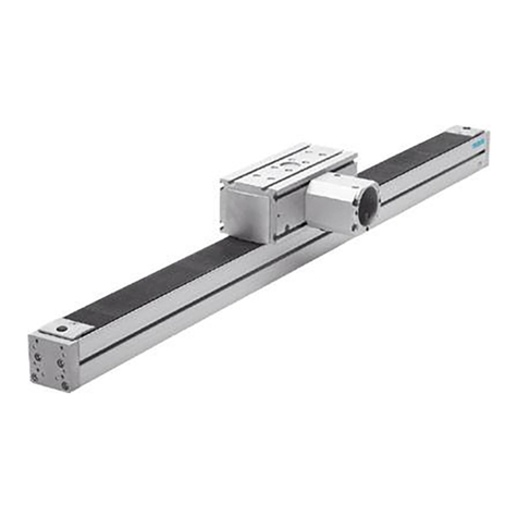
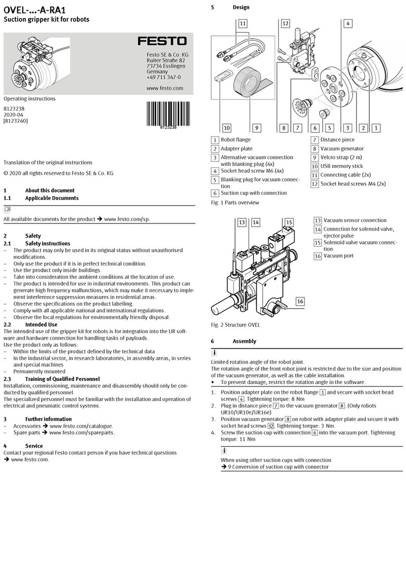
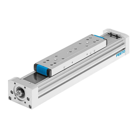
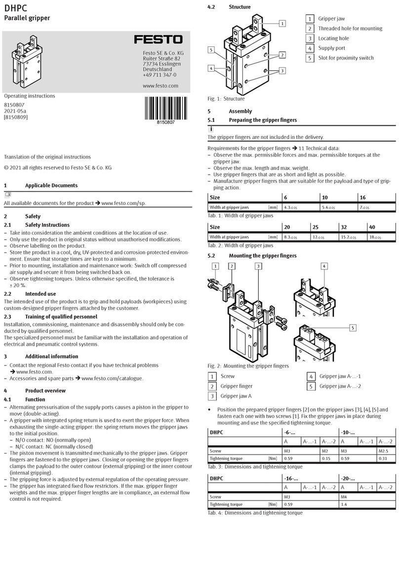
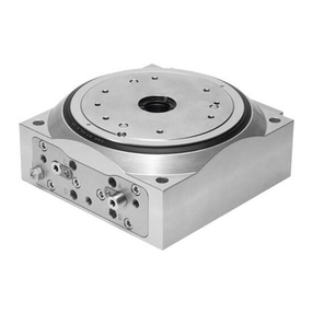
Festo ELGR series User manual

ELGR/ELGG
Festo AG & Co. KG
Postfach
73726 Esslingen
Germany
+49 711 347-0
www.festo.com
Operating instructions 8038418
1406b
[8038420]
Original: de
Toothed belt axis ELGR/ELGG English....................................
Note
Special, pre-configured axis/motor and controller combinations are available
with the OMS system (Optimized Motion Series èwww.festo.com).
Note
Installation and commissioning must be carried out only by properly qualified
personnel in accordance with these operating instructions.
1 Operating elements
1 2 3 4
Fig. 1
7
65 8 9
1Bearing cap
2Cover plate
3Slide
4Guide rod
5Toothed belt
6Drive hollow shaft
7Slot for slot nuts and foot
mounting
8Slide, operates in opposite direc
tions (ELGG only)
9Central support, optional
(ELGG only)
2 Function and application
A toothed belt on a drive hollow shaft converts the rotation of a motor into a linear
motion. The slide unit 3/8will then move backwards and forwards. The refer
ence position of the slide can be queried by means of an inductive proximity
sensor, switch lug and sensor bracket (è10. Accessories).
The toothed belt axis ELGR/ELGG is intended for positioning payloads. It is
approved for slide operating mode.
The ELGR/ELGG is not approved for operating conditions where water soluble
grease or oils can be transferred to the toothed belt.
Note
The ELGR/ELGG toothed belt axis is not self-locking: If the input torque is not
applied, the slide is freely movable. Generally, a latching function of the com
plete system can be achieved with motors with an integrated holding brake or
with high gear ratios or self-locking gear design (e.g. for vertical operation).
 Select the corresponding Festo motor from our catalogue (èCatalogue
specifications, www.festo.com/catalogue and the “Positioning Drives” sizing
software èwww.festo.com).
3 Transport and storage
Warning
During vertical transport, an unsecured slide unit can fall down (crushing).
 Transport the product with the transport packaging horizontally on the guide
rods with a secured slide.
 Take the product's weight into account. It weighs up to 30 kg.
 Ensure storage conditions as follows:
– Short storage times and
– Store in cool, dry, well-shaded locations that do not present a risk of corro
sion.
– No oils, greases or grease-dissolving vapours.
In this way you ensure the performance of the toothed belt.
4 Requirements for product use
Warning
Unexpectedly fast payloads can harm people or property (risk of crushing).
 Apply power to the drive motor, at first limited to low speeds and torques.
Free-running toothed belts can catch objects (injuries).
 Make sure that no objects, such as hair or clothing can be pulled into the
toothed belt axis by the free-running toothed belt (e.g. through a cover).
 Compare the limit values in these operating instructions with those of your
application (e.g. forces, torques, temperatures, loads, speeds).
Operation of the product in compliance with the relevant safety regulations is
contingent on adherence to the load limits.
 Take into consideration the ambient conditions at the location of use.
Corrosive environments reduce the service life of the product (e.g. ozone).
 Comply with the regulations of the trade association, the German Technical
Control Board (TÜV) or corresponding national regulations.
 Remove transport packaging such as films and cardboard.
The packaging is intended for recycling.
 Use the product in its original status, without any unauthorised product
modifications.
 Note the warnings and instructions on the product and in the relevant operating
instructions.
 Take the tolerance of the tightening torques into account. Unless otherwise
specified, the tolerance is ±20 %.
5 Installation
5.1 Mechanical installation
 Do not modify the screws and
threaded pins if not directly reques
ted to do so in these operating in
structions.
 Fit the motor onto the toothed belt
axis in accordance with the assembly
instructions for the motor mounting
kit recommended in the catalogue.
Fig. 2
For installation in a vertical or inclined position:
Warning
Falling loads can cause personal injury
and material damage (crushing). If
there is a power failure or the toothed
belt breaks, the work load will drop
down.
 Make sure that you only use motors
with an integrated spring-loaded
holding brake.
 Check whether additional external
safety measures against damage
due to breaking of the toothed
belt are required (e.g. toothed
latches or moveable bolts). Fig. 3
 Ensure an installation without distortions and bends (evenness of the bearing
surface ≤ 0.05 % of the stroke length; max. 0.5 mm).
 Place the ELGR/ELGG so that the operating elements are accessible.
 Observe the maximum sag èChapter 12. Technical data.
Note
Unsuitable mounting techniques can reduce the service life of the ELGR/ELGG
considerably.
 Make sure that the mounting components are outside the positioning range of
the slide (e.g. projecting slot nuts).
 Take into account the asymmetric
geometry of the ELGR/ELGG.
Depending on the orientation, the
slide unit or bearing cap projects
beyond the contour by the dimension
l (observe position X of the proximity
sensor). Fig. 4
 Observe the screw-in depth tmax
when using slot nuts (èFig. 7).
 Attach the ELGR/ELGG and, if avail
able, the central support (èFig. 6).
Fig. 5
 Please select the corresponding accessories from our catalogue
(èwww.festo.com/catalogue)
Profile mounting
with MUE
Slot nut mounting with
NST
Central support with
MUE/NST (ELGG only)
Profile mounting in the
groove 7
Slot nut mounting in the
slot 7
Profile or slot nut
mounting in the slot 71)
1) Attach the central support centrally, otherwise the stroke will reduce
Fig. 6
 Tighten the mounting screws evenly.
The tightening torque is summarised in the following table.
ELGR/ELGG-... 35 45 55
Screw M3 M5
Centring sleeve ZBH-7
Slot nut NST-3-M3 NST-5-M5
Screw-in depth tmax (èFig. 5) [mm] 3.8 6
Projection l (èFig. 4) [mm] 2
Tightening torque [Nm] 1 5
Fig. 7
5.2 Installation of the payload
Note
If the aluminium slide is bent against a
curved payload, the service life of the
guide will be reduced.
 Make sure that the mounting
surface of the payload is even to
within t ≤ 0.01 mm.
Fig. 8
 Place the payload so that the pull-
out torque from the force (parallel to
the axis of motion) and lever arm re
mains low.
 Fasten the payload to the slide with
4 screws and slot nuts as well as
centring elements, if needed.
(Tightening torque èFig. 7).
Fig. 9
For load geometries with projection in
the longitudinal direction of the slide:
 Make sure that the payload does not
strike against the motor or bearing
cap and, in the case of the ELGG,
against the central support.
Fig. 10
5.3 Electrical installation
To protect the end positions against uncontrolled overtravel:
 Check whether additional hardware proximity sensors are necessary.
If inductive proximity sensors are used as hardware limit switches:
 Use proximity sensors with normally-closed function.
The normally closed function protects the ELGR/ELGG against overrunning the
end position if the proximity sensor cable is broken.
 Use proximity sensors that correspond to the input of the controller being used.
If proximity sensors are used as reference switches:
 Attach the kit with switch lug (S) and
sensor bracket (L) according to the
assembly instructions (èCatalogue
specifications,
www.festo.com/catalogue).
 Avoid external influences from
magnetic or ferritic parts in the
vicinity of the proximity sensors
(minimum distance of 3 mm). Fig. 11
(S) (L)
To avoid contamination:
 Select the appropriate slot covers from our catalogue (èCatalogue specifica
tions, www.festo.com/catalogue).
6 Commissioning
Warning
Payloads can cause personal injury
and material damage (risk of
crushing).
 Make sure that, in the positioning
range:
– nobody can place his/her hand in
the path of the moving components
(e.g. through a protective guard),
– there are no foreign objects in the
path of the moving components.
It should not be possible to touch
the ELGR/ELGG until the load has
come to a complete standstill.
Fig. 12
Note
Incorrect specification values of the braking ramp in STOP situations (e.g.
EMERGENCY STOP, Quick Stop) result in an overloading of the linear axis and can
destroy it or drastically reduce its service life.
 Check the settings for all braking ramps in the controller or the higher-order
control system (deceleration values and jerk).
 Taking the travel speed, moveable load and mounting position into account,
make sure that the delay values (brake delay and delay times) are set in such
a way that the maximum drive torque or feed force of the linear axis used is
not exceeded.
 Use the “Positioning Drives” sizing software from Festo to design the linear
axis (èwww.festo.com).
Note
Block-shaped acceleration profiles (without jolt limitation) cause high peaks in
the motive force that can lead to an overloading of the drive. In addition,
positions outside the permissible range may occur as a result of overswing
effects. A jolt-limited acceleration specification reduces vibrations in the entire
system and has a positive effect on stress in the mechanical system.
 Check which closed-loop controller settings can be adapted
(e.g. jerk limitation, smoothing of the acceleration profile).
Note
The elasticity of the toothed belt delays the acceleration behaviour of the
ELGR/ELGG and results in larger acceleration values than those set on the
controller (spring effect).
 Take into account possible deviations from the acceleration values set on the
controller.
1. Check travel 2. Homing 3. Test run
Determining the
approach direction of the
motor
Comparing the real
situation with the image
in the controller
Checking the overall
behaviour
Fig. 13 : Definitions
1. Start check travel with low dynamic response.
In spite of equal control, even motors of the same type sometimes turn in the
opposite direction due to the circuitry.
2. Start homing in accordance with the operating instructions for your motor drive
system with low dynamic response to the reference switch.
3. Start a test run with low dynamic response.
4. Check whether the ELGR/ELGG fulfils the following requirements:
– The slide must be able to move through the complete intended positioning
cycle.
– The slide must stop as soon as it reaches a limit switch.
5. In the event that the proximity sensors fail to respond: èChapter 11 “Fault
clearance” and the operating instructions for the proximity sensors.
7 Operation
Warning
Payloads can cause personal injury and material damage (risk of crushing).
 Make sure that:
– nobody can place his/her hand in the path of the moving components
(e.g. through a protective guard),
– there are no foreign objects in the path of the moving components.
It should not be possible to touch the ELGR/ELGG until the load has come to a
complete standstill.
If the motor turns in the wrong direction:
Note
When a motor with absolute value
encoder is dismantled
(e.g. when turning the motor around),
the reference position is lost.
 Start homing in accordance with
the chapter “Commissioning” to
re-reference the positioning cycle.
For the ELGR with the OMS variant
(Optimized Motion Series), the previ
ous parameter set of the OMS system
is invalid when moving the motor. A
new parameter set is essential.
 Load the new parameter set
according to the new motor
position (M) into the controller
(èwww.festo.com).
 Repeat the commissioning process
with the new parameter set. Com
missioning with the OMS identifica
tion number specified on the
product is no longer possible.
Fig. 14
FL
FR RL
RR
(M)
8 Maintenance and care
Warning
Payloads can cause personal injury and material damage (risk of crushing).
If a toothed belt breaks in combination with a vertically or diagonally fitted
ELGR/ELGG, the work load will fall down.
 If there is evidence of wear, return the ELGR/ELGG to Festo for repair.
Signals from the control system can cause unintentional movement of the
ELGR/ELGG.
 Switch off the control system when conducting any work on the ELGR/ELGG
and secure it from being restarted accidentally.
Cleaning and maintenance:
 Clean the ELGR/ELGG as required with a soft cloth.
Any media which will not damage the material may be used as cleaning agents.
Relubrication of the ELGR/ELGG is not permissible.
 Regularly check the play in the plain-bearing guide according to your
application. Depending on the load, the guide backlash rises with increasing
duration of operation.
9 Disassembly and repair
Note
Retensioning of the toothed belt reduces its service life considerably. In addi
tion, the technical data, e.g. the feed constant, change.
 Make sure that the toothed belt is not retensioned.
The pretension of the toothed belt is designed in such a way that it does not
need to be retensioned over its service life.
 Recommendation: Send the ELGR/ELGG to our repair service.
This way the required fine tuning and tests will be taken into special considera
tion.
 Information about spare parts and accessories can be found at:
www.festo.com/spareparts
10 Accessories
Note
 Please select the corresponding accessories from our catalogue
èwww.festo.com/catalogue
11 Fault clearance
Malfunction Possible cause Remedy
Squeaking
noises,
vibrations or
rough running
The coupling is mounted
too tight
Comply with the permissible
coupling distances (èAssembly
instructions for the motor
mounting kit)
Tension Install the ELGR/ELGG so it is free
from tension (observe the
evenness of the bearing surface
èChapter 5.1 Mechanical
installation)
Modify travel speed
Incorrect regulator
settings
Modify the regulator parameters
Defective bearing Return the ELGR/ELGG to Festo for
repair
Toothed belt or slide
elements worn
Slide does not
move
Loads too high Reduce load mass
Guide jammed Reduce torques
Clamping hub spins Check mounting of the motor
mounting kit (coupling)
Slide travels
beyond the end
position
The proximity sensors do
not react
Check the mounting level of the
proximity sensors, connections and
controller
Toothed belt
jumps off
Toothed belt
pretensioning too low
Return the ELGR/ELGG to Festo for
repair
Incorrect regulator
settings
Change the regulator parameters
Loads too high Reduce load mass
Reduce travel speed
Stroke of ELGG
too low
Incorrect position of the
central support
Attach the central support at the
exact central position
Fig. 15
12 Technical data
ELGR/ELGG-... 1) 35 45 55
Design ELGR Electromechanical linear axis with
toothed belt
ELGG additionally with opposing slides
Guide –Recirculating ball bearing guide
GF Plain-bearing guide
Installation position any
Max. feed force Fx [N] 50 100 350
Max. driving torque [Nm] 0.46 1.24 5
Idle drive torque 2) ELGR [Nm] 0.1 0.2 0.4
ELGG [Nm] 0.18 0.3 0.5
Max. speed –[m/s] 3
GF [m/s] 1
Max. acceleration [m/s2]50
Repetition accuracy –[mm] ±0.1
GF [mm] –
Feed constant 3) [mm/rev] 58 78 90
Max. deflection [mm] 0.5
Ambient temperature –[°C] –10 … +50
GF [°C] 0 … +40
Degree of protection IP20
Note on materials Contains PWIS (paint-wetting impair
ment substances)
Materials
– Cover, slide unit, profile Anodised aluminum
– Guide, ball bearings, screws,
retaining rings, clamping element
Steel
– Clamping component, clamping plates Beryllium bronze
– Toothed belt Fibreglass-reinforced polychloro
prene
– Cover Polyamide/polystyrene
Weight of ELGR/ELGG (with standard slide, without central support, without
motor)
– 0 mm stroke –[kg] 1.47 / 1.87 3.23 / 4.23 5.44 / 7.16
GF [kg] 1.36 / 1.89 3.07 / 4.28 5.08 / 7.24
– per metre of stroke [kg] 2.45 / 4.88 5.00 / 10.0 7.80 / 15.6
1) The following tool is available for sizing:
Positioning Drives sizing software èwww.festo.com
2) Measured at a speed of 0.2 m/s
3) Nominal value, varies due to component tolerances
Fig. 16
Permissible forces and torque loading 1) 2)
ELGR/ELGG-... 35 45 55
Fymax = Fzmax –[N] 50 100 300
Mxmax –[Nm] 2.5 515
Mymax = Mzmax –[Nm] 816 48
Fymax = Fzmax GF [N] 50 100 300
Mxmax GF [Nm] 12.5 5
Mymax = Mzmax GF [Nm] 4 8 16
Formula for combined loadings:3)
2nd moment of area Y
Z
–Iy [mm4]3 771 15 707 38 349
–Iz [mm4]188 574 807 546 1 853 601
1) With a standard slide unit
2) The following tool is available for sizing:
Positioning Drives sizing software èwww.festo.com
3) The load applies per slide for the ELGG with central support
Fig. 17
Speed v as a function of the rotational speed n
ELGR/ELGG-TB-35
ELGR/ELGG-TB-45
ELGR/ELGG-TB-55
n
Fig. 18
Acceleration a as a function of the payload m
Note
For the plain-bearing guide (GF) it is recommended to reduce the acceleration to
minimise overswings and increase positioning accuracy.
ELGR/ELGG-TB-35
horizontal
vertical
ELGR/ELGG-TB-45
horizontal
vertical
ELGR/ELGG-TB-55
horizontal
vertical
Fig. 19

Other manuals for ELGR series

1

This manual suits for next models

7

Other Festo Industrial Equipment manuals

Festo ELGA-TB Parts list manual

Festo

Festo ELGA-TB Parts list manual

Festo MS6-SV-C-MK User manual

Festo

Festo MS6-SV-C-MK User manual

Festo MS6-SV Series User manual

Festo

Festo MS6-SV Series User manual

Festo HGP A Series User manual

Festo

Festo HGP A Series User manual

Festo WA-2 User manual

Festo

Festo WA-2 User manual

Festo EPCE-TB User manual

Festo

Festo EPCE-TB User manual

Festo EGSL User manual

Festo

Festo EGSL User manual

Festo DGE ZR-RF Series User manual

Festo

Festo DGE ZR-RF Series User manual

Festo GRLZ User manual

Festo

Festo GRLZ User manual

Festo YXC Series User manual

Festo

Festo YXC Series User manual

Festo VABM-B10 EEE Series User manual

Festo

Festo VABM-B10 EEE Series User manual

Festo DYSW-...-Y1F Series User manual

Festo

Festo DYSW-...-Y1F Series User manual

Festo VMPA1-FT-NW 10 Series User manual

Festo

Festo VMPA1-FT-NW 10 Series User manual

Festo MPS 8049013 User manual

Festo

Festo MPS 8049013 User manual

Festo MS9-EX2 Series User manual

Festo

Festo MS9-EX2 Series User manual

Festo STAF-...-P-A-R series User manual

Festo

Festo STAF-...-P-A-R series User manual

Festo YXCF User manual

Festo

Festo YXCF User manual

Festo 571815 User manual

Festo

Festo 571815 User manual

Festo HMPL-12-KP Series User manual

Festo

Festo HMPL-12-KP Series User manual

Festo MPS 8046325 User manual

Festo

Festo MPS 8046325 User manual

Festo DNCB Setup guide

Festo

Festo DNCB Setup guide

Festo Checkbox Compact CHB-C-C User manual

Festo

Festo Checkbox Compact CHB-C-C User manual

Festo VMPA -RV Series User manual

Festo

Festo VMPA -RV Series User manual

Festo Distributing Station User manual

Festo

Festo Distributing Station User manual

Popular Industrial Equipment manuals by other brands

SA POWERNET EX MDU user manual

SA

SA POWERNET EX MDU user manual

CMO VALVES FL Series Instruction and maintenance manual

CMO VALVES

CMO VALVES FL Series Instruction and maintenance manual

IMAO QLSWH Series manual

IMAO

IMAO QLSWH Series manual

Dongguan Xin Bao Instrument Transport Simulation Vibration Table Operation manual

Dongguan Xin Bao Instrument

Dongguan Xin Bao Instrument Transport Simulation Vibration Table Operation manual

Berthold 40876-01 operating manual

Berthold

Berthold 40876-01 operating manual

GIGAIPC QBiX-Pro-BYTA1900HD-A1 quick start guide

GIGAIPC

GIGAIPC QBiX-Pro-BYTA1900HD-A1 quick start guide

Bosch Rexroth BS 2/C Series Assembly instructions

Bosch

Bosch Rexroth BS 2/C Series Assembly instructions

Hotronix Power Platen quick start guide

Hotronix

Hotronix Power Platen quick start guide

BONFIGLIOLI 700C Series Installation and service manual

BONFIGLIOLI

BONFIGLIOLI 700C Series Installation and service manual

Grundfos CR Installation and operating instructions

Grundfos

Grundfos CR Installation and operating instructions

Endress+Hauser Cleanfit P CPA471 operating instructions

Endress+Hauser

Endress+Hauser Cleanfit P CPA471 operating instructions

Altronic GTI Bi-Fuel Installation & operating manual

Altronic

Altronic GTI Bi-Fuel Installation & operating manual

Euromair Jet Mix PRO instruction manual

Euromair

Euromair Jet Mix PRO instruction manual

Carlisle ms 8132 0 Series Service manual

Carlisle

Carlisle ms 8132 0 Series Service manual

Frimax MAXON Ocultas TE-20 Series Manual de usuario

Frimax

Frimax MAXON Ocultas TE-20 Series Manual de usuario

Emerson Liebert eXL installation manual

Emerson

Emerson Liebert eXL installation manual

Twiflex GMR-S quick start guide

Twiflex

Twiflex GMR-S quick start guide

Muller HYDRO-GUARD 200 Series Operating instructions manual

Muller

Muller HYDRO-GUARD 200 Series Operating instructions manual

manuals.online logo
manuals.online logoBrands
  • About & Mission
  • Contact us
  • Privacy Policy
  • Terms and Conditions

Copyright 2025 Manuals.Online. All Rights Reserved.