PGVA Manual
Festo SE & Co. KG Page 6 of 20
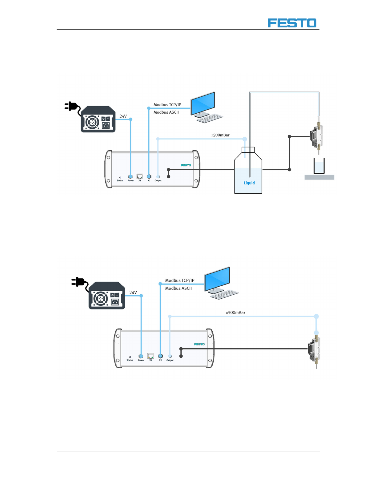
2 Communications
2.1 Getting Started using the GUI
There are two ways to establish communication with the GUI. Both are shown in the following table below. If
a connection hasn’t been established, many of the GUI elements will remain grayed out.
1. Select the COM port that will be used for ASCII Modbus communication with the PGVA
2. Select the IP address of the PGVA
3. Refreshes the COM ports. Can be used when the serial cable is plugged into the PC after the GUI
application is started.
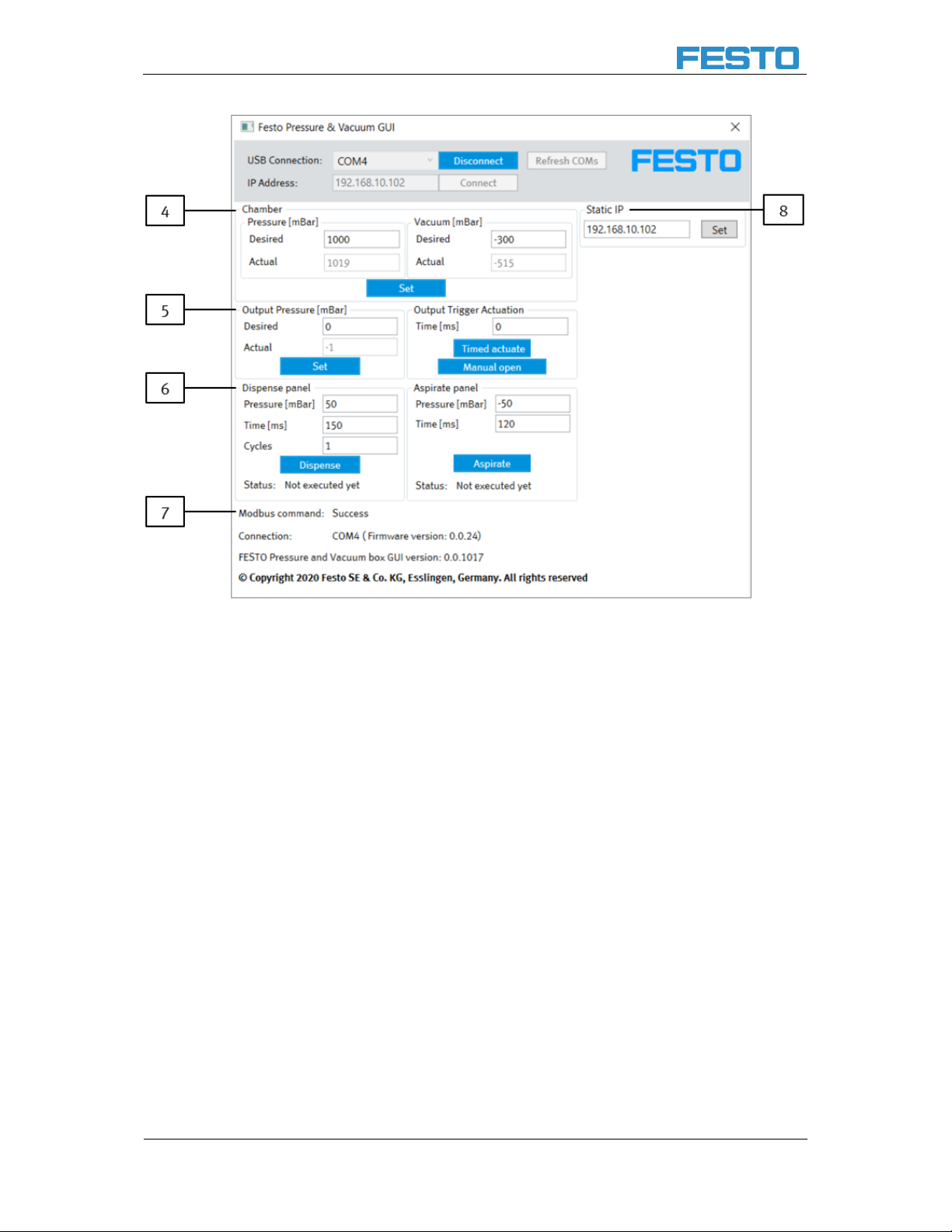
4. Chamber panel.
1. "Desired" textbox - user enters pressure in millibars and presses the "Set" button. Once
the pressure for the selected chamber (pressure or vacuum) is reached.
1. The individual pressure range is between 200 and 1000 [mbar].
2. The individual vacuum range is between -160 and -640 [mbar].
2. pump stops pressurizing that chamber. Note: Firmware implements hysteresis:
1. The pump will start pressurizing the pressure chamber if the pressure in it falls
below "Desired" - 100 mbar.
2. The pump will start pressurizing the vacuum chamber if the pressure in it goes
above "Desired" + 40 mbar.
3. "Actual" textbox - displays the current pressure in the corresponding chamber (pressure or
vacuum) in millibars
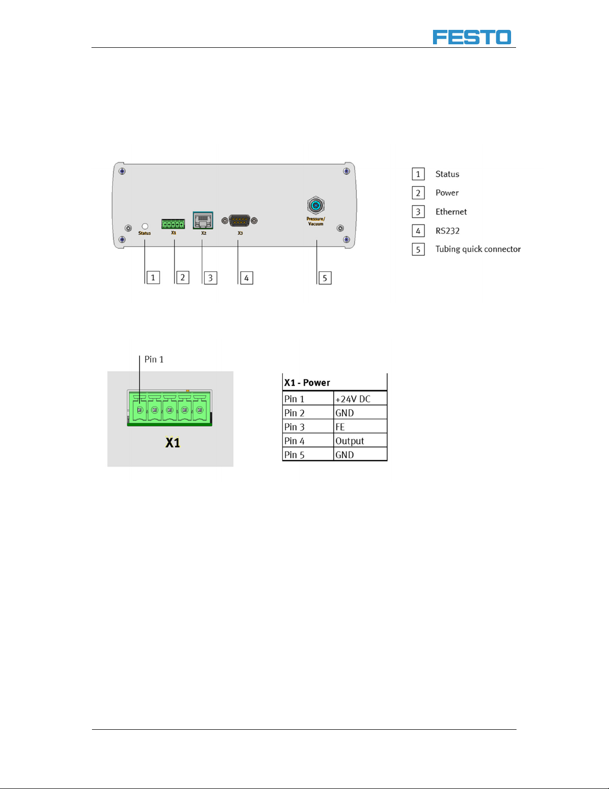
5. Output pressure panel
1. "Desired" textbox - user enters the desired pressure in millibars and presses the "Set"
button. The device will command via DAC the VEAB to regulate the pressure set by the
user.
2. "Actual" textbox - displays the current pressure regulated by the VEAB via ADC in millibars
3. The additional output trigger can either be used as a time-dependent actuation or as a
manual on / off switch.
Note:
In case the connection will be made over ethernet, please consider the following note. The PC must be on
the same network as the Box. The Ethernet cable must be plugged in before starting the box. If the
Ethernet cable is plugged in after the PGVA has started Ethernet connection will not be possible.