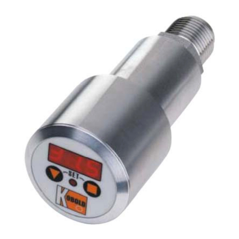
Kobold SEN-98 User manual

Operating Instructions
for
Pressure Transmitter
Model: SEN-98/-99

SEN-98/-99
page 2 SEN-98/-99 K03/0322
We don’t accept warranty and liability claims neither upon this publication nor in
case of improper treatment of the described products.
The document may contain technical inaccuracies and typographical errors. The
content will be revised on a regular basis. These changes will be implemented in
later versions. The described products can be improved and changed at any time
without prior notice.
© Copyright
All rights reserved.

SEN-98/-99
SEN-98/-99 K03/0322 page 3
1. Contents
1.Contents ....................................................................................................... 3
2.Note .............................................................................................................. 4
3.Instrument Inspection .................................................................................... 5
4.Product Label ................................................................................................ 5
5.Regulation Use ............................................................................................. 6
6.Electrical Connection .................................................................................... 7
7.Installation ..................................................................................................... 8
8.Recalibration and maintenance..................................................................... 9
9.Technical Information .................................................................................. 10
10.Order Codes ............................................................................................... 12
11.Dimensions (in mm) .................................................................................... 13
12.EU Declaration of Conformance ................................................................. 14
Manufactured and sold by:
Kobold Messring GmbH
Nordring 22-24
D-65719 Hofheim
Tel.: +49(0)6192-2990
Fax: +49(0)6192-23398
E-Mail: [email protected]
Internet: www.kobold.com

SEN-98/-99
page 4 SEN-98/-99 K03/0322
2. Note
Please read these operating instructions before unpacking and putting the unit
into operation. Follow the instructions precisely as described herein.
The instruction manuals on our website www.kobold.com are always for currently
manufactured version of our products. Due to technical changes, the instruction
manuals available online may not always correspond to the product version you
have purchased. If you need an instruction manual that corresponds to the
purchased product version, you can request it from us free of charge by email
([email protected]) in PDF format, specifying the relevant invoice number and
serial number. If you wish, the operating instructions can also be sent to you by
post in paper form against an applicable postage fee.
The devices are only to be used, maintained and serviced by persons familiar
with these operating instructions and in accordance with local regulations
applying to Health & Safety and prevention of accidents.
When used in machines, the measuring unit should be used only when the
machines fulfil the EC-machine guidelines.
Devices with max. allowable pressure ≤200 bar:
as per PED 2014/68/EU
In acc. with Article 4 Paragraph (3), "Sound Engineering Practice", of the PED
2014/68/EU no CE mark.
The instrument safety level depends on the right choice and installation of the
instrument model and on the maintenance, procedures established by the
manufacturer.
Technicians in charge of the instrument selection, installation and maintenance
should be able to understand if the instrument conditions of use could affect its
right functioning and lead to any premature damage or breaking.
It is essential that these procedures included in the plants regulations should be
carried out by qualified staff. An improper use could be dangerous for the
instrument itself and cause damages to the staff and to the plant.
In order to choose correctly the right instrument, it is highly recommended to read
the most recent catalogue sheets available on-line at www.kobold.com

SEN-98/-99
SEN-98/-99 K03/0322 page 5
3. Instrument Inspection
Instruments are inspected before shipping and sent out in perfect condition.
Should damage to a device be visible, we recommend a thorough inspection of
the delivery packaging. In case of damage, please inform your parcel service /
forwarding agent immediately, since they are responsible for damages during
transit.
Scope of delivery:
The standard delivery includes:
Pressure Transmitter model: SEN-98/-99
4. Product Label

SEN-98/-99
page 6 SEN-98/-99 K03/0322
5. Regulation Use
The pressure transmitter turns the input pressure into an output electrical signal.
The electrical signal changes in proportion to the input pressure level.
Any use of the Pressure Transmitter, model: SEN-98/-99, which exceeds the
manufacturer’s specification may invalidate its warranty. Therefore, any resulting
damage is not the responsibility of the manufacturer. The user assumes all risk
for such usage.
Warning!
The manufacturer disclaims all responsibility in case of damages
caused by the improper use of the product and by the non-respect of
the instructions reported in this manual.
- Follow carefully the specific safety rules in case of measuring oxygen
pressure, acetylene, inflammable or toxic gas or liquids.
- Disconnect the instruments only after depressurization of the system.
- The process fluids residuals in the disassembled instruments could
affect people, the environment and the system. It is highly
recommended to take proper precautions.
Warning!
Before installation be sure that the right instrument has been selected
following the working conditions and in particular the range, the
working temperature and the compatibility between the material used
and the process fluid.
- This manual does not concern the instruments conforming to
standard 94/9/CE (ATEX).
- The product warranty is no longer valid in case of non-authorized
modifications and of wrong use of the product.
- The user is totally responsible for the instrument installation and
maintenance.
- Handle and carefully stock the instrument used for toxic or
inflammable liquids measurement

SEN-98/-99
SEN-98/-99 K03/0322 page 7
6. Electrical Connection
The transmitter metal case should always be connected to ground through the
process connection thread in order to protect it from disturbances due to
electromagnetic fields or electrostatic charges.
If it wouldn’t be possible to do so connect the transmitter to ground through the
connector and the cable screen.
Cable output
Cable output

SEN-98/-99
page 8 SEN-98/-99 K03/0322
7. Installation
Before installing electrical instrument safely and securely into a plant or a system
the user should verify the instrument suitability to the plant characteristics and the
correct installation. After installation the user should verify that the instrument is
not exposed to any source of heat exceeding the established ambient limits.
Secure the instrument thread through a special key/wrench on the process
connection hexagon without grasping the case by the hands.
Secure the instrument thread through a special key/wrench on the process
connection hexagon (20…30Nm). The correct torque depends on the type of
process connection and the type of seal used (form and material).
If the connection thread is conical the instrument is tightened through a simple
screwing on the plug. In order to improve the thread tightness, it is recommended
to place a PTFE layer on the male thread.
If the instrument is equipped with a fluid diaphragm seal the connection should be
clamped on the diaphragm otherwise the calibration could be compromised.
Connector Assembling EN 175301-803 Form A
Disassemble the connectors as in fig. 1 and connect the cables as in fig. 2.
Reassemble the connector and fix it on the transmitter.
Figure 1 – Exploded view of the connector Figure 2 – Wires connection
Warning!
The IP grade according to standard EN-60529-1:1992 is guaranteed
only if the female connector equipped with a connection cable is
mounted on the instrument and all the other components are
assembled correctly.

SEN-98/-99
SEN-98/-99 K03/0322 page 9
8. Recalibration and maintenance
In models the zero and the full scale range can be adjusted as follows
(see figure 3):
- Connector disassembling (see fig. 1)
- Zero adjustment (Z)
- Span adjustment(S)
Figure 3 - Adjustment
In case a complete recalibration is necessary please contact KOBOLD.

SEN-98/-99
page 10 SEN-98/-99 K03/0322
9. Technical Information
Ranges: 0 ...1/0 ... 600 bar, relative,
(0 ...15/0 ...10 000 psi, relative)
-1... 0/-1… + 24 bar, relative;
(-30"… 0/-30"… 350 psi, relative)
0 ...1/0 …16 bar, absolute
(0 …15/0 … 200 psi, absolute)
Accuracy (% span): ≤0.25 typical; ¡Ü 0.5 max.
Calibration: Limit-point as per DIN 16086
Repeatability: ≤0.15% of span
Thermal drift: ≤0.04 % span / °C (for ranges < 2 bar)
≤0.02 % span / °C (for ranges ¡Ý 2 bar)
Process fluid
temperature: -25 ... +100 °C; depending on gasket type
Ambient temperature: -25 ... +85 °C
Storage temperature: -40 ...+85 °C
Output signals: 4 ... 20 mA, 0 ... 5 VDC, 0...10 VDC
Supply and max. load: See on page 3
Response time
(10 ... 90%): < 3 ms
Zero calibration: ± 10% span typical
Span calibration: ± 10% span typical
Compensated
temperature range: 0 ... +80 °C
Process connection: AISI 316L stainless steel
Sensor: Ceramic
Case: Stainless steel, vented for pressure
ranges ≤230 psi (≤ 16 bar)
O-ring: FKM
Electric connection: *EN 175301-803 form A, exit for
cables ø 0.23 ... 0.35” (6 ... 9 mm)
Protection degree: IP 65 as per IEC 529 / EN 60529
Weight: 0.39 Ibs (0.18 kg)

SEN-98/-99
SEN-98/-99 K03/0322 page 11
Ranges
bar, relative
Overpressure
bar, relative
Burst pressure
bar, relative
-1...0 5 7
-1...0.6 5 7
-1...1.5 5 7
-1...3 10 12
-1...5 20 25
-1...9 20 25
-1...15 40 50
-1...24 100 120
0...1/0...2.5 5 7
0...4 10 12
0...6/0...10 20 25
0...16 40 50
0...25/0...40 100 120
0...60/0...100 200 250
0...160/0...250 500 600
0...400 600 800
0...600 800 900
Other ranges available on demand. Units of measurement available in MPa, kPa too
Absolute pressure ranges have same overpressure limits as gauge pressure ranges
Ranges
psi, relative
Overpressure
psi, relative
Burst pressure
psi, relative
-30...0 in H
g
/psi 72 100
-30...30 in H
g
/psi 72 100
-30...60 in H
g
/psi 145 175
-30...100 in H
g
/psi 290 360
-30...150 in H
g
/psi 290 360
0...15/0...30 72 100
0...60 145 175
0...100/0...160 290 360
0...300 580 725
0...600 1450 1740
0...1000/0...1500 2900 3625
0...2000/0...3000 7250 8700
0...5000/0...6000 8700 11600
0...10000 11600 13050
Other ranges available on demand. Units of measurement available in MPa, kPa too

SEN-98/-99
page 12 SEN-98/-99 K03/0322
10. Order Codes
Order Details (Example: SEN-9800 0 B075 A 0)
Model Output Measuring range Mechanical
connection
Options
Gauge pressure
ranges
SEN-9800...
(with electrical plug
connection EN
175301-803)
SEN-98303)...
(M12x1 male
electrical connection)
SEN-9840 1)3)...
(2m PVC cable,
IP65)
SEN-98501)3)...
(2m Polyurethane
cable, IP68)
0 = 4-20 mA,
2-wire
(standard)
13) = 0...5 VDC
(8...30 VDC)
23) = 0...10 VDC
(14...30 VDC)
Gauge pressure
ranges
C 315 = -1...0 bar
C 5053) = -1...0.6
bar
C 5153) =-1...1.5
bar
C 5253) = 1...3 bar
C 5353) = -1...5 bar
C 5453 = -1...9 bar
C 5553 = -1...15 bar
C 5653 = -1...24 bar
B 025 = 0...1 bar
B 035 = 0...1.6 bar
B 045 = 0...2.5 bar
B 055 = 0...4 bar
B 065 = 0...6 bar
B 075 = 0...10 bar
B 085 = 0...16 bar
A 095 = 0...25 bar
A 105 = 0...40 bar
A 115 = 0...60 bar
A 125 = 0...100 bar
A 135 = 0...160 bar
A 145 = 0...250 bar
A 155 = 0...400 bar
A 1653) = 0...600
bar
H 3153) = -30...0 in Hg
H 3173) = 30 in
Hg/psig
H 3193) = -30…60 in
Hg/psig
H 3213) = -30…100 in
Hg/psig
H 3233) = -30…150 in
Hg/psig
P 0253) = 0…15 psig
P 0453) = 0…30 psig
P 0573) = 0…60 psig
P 0653) = 0…100 psig
P 0773) = 0…160 psig
P 0853) = 0…200 psig
P 0863) = 0…250 psig
P 0883) = 0…300 psig
P 1003) = 0…500 psig
P 1053) = 0…600 psig
P 1153) = 0…1000
psig
P 1263) = 0…1500
psig
P 1303) = 0…2000
psig
P 1403) = 0…3000
psig
P 1473) = 0…4000
psig
P 1503) = 0…5000
psig
P 1573) = 0…6000
psig
P 1623) = 0…8000
psig
P 1653) = 0…10000
psig
A = G ½ ,
male
(standard)
B3) = G ¼ ,
male
F3) = ½ „
NPT, male
G3) = ¼ „
NPT, male
0 = without
K 2)3) =
accuracy
≤0.25% of
span
S3) =
oxygen
service
Y3) =
special
option
(specify in
text)
Absolute pressure
ranges
SEN-99003)...
With electrical plug
connection EN
175301-803)
SEN-98303)...
(M12x1 male
electrical connection)
SEN-98401)3)...
(
2 m PVC cable,
Absolute pressure ranges3)
B 025 = 0...1 bar
B 035 = 0...11.6 bar
B 045 = 0...2.5 bar
B 055 = 0...4 bar
B 065 = 0...6 bar
B 075 = 0...10 bar
B 085 = 0...16 bar
B 095 = 0...25 bar

SEN-98/-99
SEN-98/-99 K03/0322 page 13
IP65)
SEN-98501)3)...
(2 m Polyurethane
cable, IP68
)
1)zero calibration not available
2)for pressure ranges ≤600 psi (40 bar); not for model SEN-99...
3) minimum order quantity = 10 pieces per item (identical model code)
Output signal
code
4…20 mA
(standard)
0
0…5 VDC
1
0…10 VDC
2
No. of wires 2 3 3
Load max.
(
Ω
)
R
L ≤
(
Vin-8
)
/0.02 RL≥5
K
ΩR
L ≥ 10
K
Ω
Suppl
y
: + Vin
(
VDC
)
10…30 8…30 14…30
Ground
(
please refer to chapter 6
)
11. Dimensions (in mm)
FL
(
mm
)
A
–
G ½ A
(
standard
)
20
B
–
G ¼
A
13
F
–
½ -14 NPT 20
G
–
¼ -18 NPT 13

SEN-98/-99
page 14 SEN-98/-99 K03/0322
12. EU Declaration of Conformance
We, KOBOLD Messring GmbH, Hofheim-Ts, Germany, declare under our sole
responsibility that the product:
Pressure Transmitter Model: SEN-98/-99
to which this declaration relates is in conformity with the standards noted below:
EN 61326-1:2013 Electrical equipment for measurement, control and
laboratory use - EMC requirements - Part 1: General requirements
Also, the following EC guidelines are fulfilled:
2014/30/EU EMC Directive
2011/65/EU RoHS (category 9)
2014/68/EU PED
200 bar
Category I
Module D
Notified body: DNV GL
Certificate number: PEDD0000002
mark CE 0575
Hofheim, 02. November 2017
H. Peters M. Wenzel
General Manager Proxy Holder
This manual suits for next models
1
Table of contents
Other Kobold Transmitter manuals

Kobold
Kobold PAD User manual

Kobold
Kobold NGM User manual

Kobold
Kobold Heinrichs UMC3 User manual

Kobold
Kobold NEO-7 Series User manual

Kobold
Kobold APM-1 User manual

Kobold
Kobold LCI User manual

Kobold
Kobold AFB User manual

Kobold
Kobold KAL-7000 Series User manual

Kobold
Kobold DWD User manual

Kobold
Kobold PAS User manual