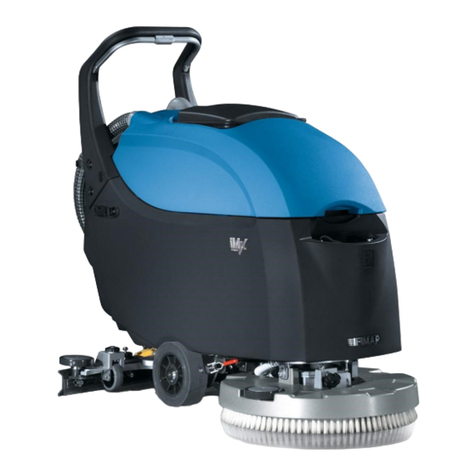
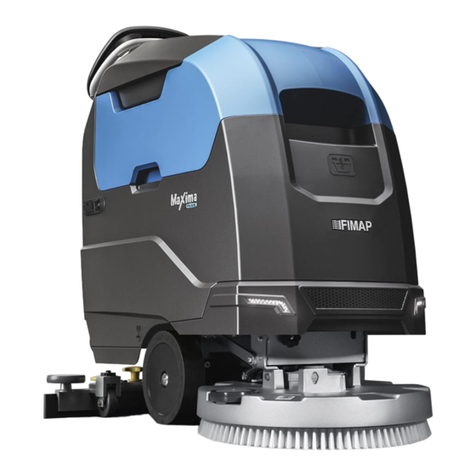
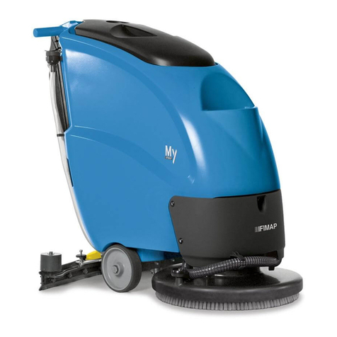
Fimap BMg User manual

ORIGINAL INSTRUCTION DOC. 10085626 - Ver. AB - 04-2019
PROFESSIONAL SCRUBBING MACHINES
GUIDE TO CONFIGURING THE USER INTERFACE
DRIVE
0000.00 100%
BMg - MMg
Magna


CONTENTS
CONTENTS............................................................................................................................................................... 3
SYMBOLS USED IN THE MANUAL ........................................................................................................................ 4
PURPOSE AND CONTENT OF THE MANUAL ....................................................................................................... 4
TARGET GROUP...................................................................................................................................................... 4
STORING THE USE AND MAINTENANCE MANUAL............................................................................................. 4
GENERAL SETUP: LANGUAGE ............................................................................................................................. 5
CHANGING THE DISPLAY LANGUAGE ............................................................................................................... 5
GENERAL SETUP: HOUR METER.......................................................................................................................... 5
CHANGING THE PARTIAL HOUR METER DISPLAYED ...................................................................................... 5
GENERAL SETUP: ZONE PROGRAMMING........................................................................................................... 6
ACTIVATION OR DEACTIVATION OF THE WORK ZONES MODE ..................................................................... 6
ACTIVATION OR DEACTIVATION OF THE MANUAL MODE ............................................................................... 6
CHANGING THE PROGRAM ZONE PARAMETERS............................................................................................ 7
GENERAL SETUP: ALARMS................................................................................................................................... 8
VIEWING THE LIST OF ALARMS ......................................................................................................................... 8
GENERAL SETUP: MONITOR ................................................................................................................................. 8
3

The descriptions contained in this document are not binding. The company therefore reserves the right to make any modications at any time to
elements, details, or accessory supply, as considered necessary for reasons of improvement or manufacturing/commercial requirements. The
reproduction, even partial, of the text and drawings contained in this document is prohibited by law.
The company reserves the right to make any technical and/or supply modications. The images are for reference purposes only, and
are not binding in terms of design and supply.
SYMBOLS USED IN THE MANUAL
Information symbol:
Indicates additional information for the operator, to improve the use of the device.
Warning symbol:
Carefully read the sections preceded by this symbol meticulously following the instructions indicated for the safety of the operator and
the device.
PURPOSE AND CONTENT OF THE MANUAL
The aim of this manual is to provide customers with all the information needed to program and customise the machine in the safest, most
appropriate and most autonomous way possible. The operators and qualied technicians must carefully read the instructions in this manual
before carrying out any operations on the machine. If in doubt about the correct interpretation of instructions, contact your nearest Customer
Service Centre to obtain the necessary clarications.
TARGET GROUP
This manual is written both for operators and for qualied machine maintenance technicians. Operators must not perform operations that should
be carried out by qualied technicians. The manufacturer is not liable for damages resulting from failure to comply with this veto.
STORING THE USE AND MAINTENANCE MANUAL
The following document must be stored in its special pouch close to the machine, protected from liquids and anything else that could
compromise its legibility.
4

From the work screen, by pressing the "SETTING" button on the operator menu screen, the following screens can be displayed:
• Language
• Hour meter
• Zone programming
• Parameters
• Monitor
• Alarms
N.B.: pressing the "EXIT" key returns you to the previous menu screen.
To access the "Main Menu" screen, proceed as follows:
1. With the machine on, press the menu button (1) on the working screen (Fig.1).
2. Press the setting (2) (Fig.2).
OFFICE
0000.00 100%
ECO mode
0000.00 100%
1 2
21
CHANGING THE DISPLAY LANGUAGE
To change the language of the graphic display interface, proceed as follows:
1. Go to the "Main Menu" screen and select the "Language" option (1), on the left-hand side
of the screen.
N.B.: when an option is selected from the list, this is highlighted.
2. As soon as the "LANGUAGE" option is selected, the languages that can be chosen will
appear on the right-hand side of the screen.
3.
4. Select the desired language, for example, Italian (2), and press the "EXIT" button.
N.B.: The language will be changed the next time the machine is turned on.
Main Menu
Language
HourMeter
Zone Programming
Parameters
Monitor
Alarms
Exit
English
Italiano
French
German
Spanish
1
2
CHANGING THE PARTIAL HOUR METER DISPLAYED
To change the partial hour meter displayed, proceed as follows:
1. Go to the "Main Menu" screen and select the "Hour Meter" option (1), on the left-hand
side of the screen.
N.B.: when an option is selected from the list, this is highlighted.
2. As soon as the "Hour Meter" option (1) is selected, all of the programmed hour meters
stored in the machine will be displayed on the right-hand side of the screen.
N.B.: all of the programmed hour meters stored in the machine can be viewed on the
right-hand side of the screen:
• Key: hour meter for the machine's starter key.
• Traction: hour meter for the machine's traction motor.
• Brushes: hour meter for the machine's brush motor.
• Vacuum: hour meter for the machine's suction motor.
3. To change the hour meter displayed on the work screen, click on the drop-down menu
(2) that can be found in the upper right-hand corner of the screen.
N.B.: when the button (2) is pressed, the pop-up menu for the hour meters will appear at the centre of the screen.
4. Select your preferred hour meter from those available, for example "Traction" (3).
Main Menu
Language
HourMeter
Zone Programming
Parameters
Monitor
Alarms
Exit
Key
Traction
Brushes
Vacuum
Exit
Reset
Main Menu
Language
HourMeter
Zone Programming
Parameters
Monitor
Alarms
Exit
DISPLAYED
TOTAL PARTIAL
Key 0000.00 0000.00
Traction 0000.00 0000.00
Brushes 0000.00 0000.00
Vacuum 0000.00 0000.00
Traction
1
2
3
GENERAL SETUP: HOUR METER
GENERAL SETUP: LANGUAGE
5

ACTIVATION OR DEACTIVATION OF THE WORK ZONES MODE
To activate or deactivate the "PROGRAM ZONE" work mode, proceed as follows:
1. Go to the "Main Menu" screen and select the "Zone Programming" option (1), on the left-hand side of the screen.
N.B.: when the button (1) is pressed, the pop-up menu for inserting the password will appear at the centre of the screen.
2. Enter the level 4 or level 3 password and press "Enter" (2) to conrm.
N.B.: The default level 4 password is 1000.
N.B.: if you enter one of the password digits incorrectly, simply press the key (3) to delete it.
3. When the correct password has been entered, the "Zone Programming" menu will appear.
4. To activate or deactivate the "ZONE" work mode, and to view the button dedicated to this mode in the work Main Menu, simply move the
"ZONE" indicator (4) on the right-hand side of the display to the right.
N.B.: if the indicator is moved to the right, the mode will be activated and the word "ON" will appear on the indicator (4); if it is moved to the
left, the mode will be deactivated and the word "OFF" will appear on the indicator (4).
OFF
Programmazione Zone
Zone 1
Zone 2
Zone 3
Zone 4
Esci
ZONE
MANUAL
ON
Main Menu
Language
HourMeter
Zone Programming
Parameters
Monitor
Allarms
Exit
Italiano
English
Spanish
French
German
Enter
Insert code
1
3
4
2
GENERAL SETUP: ZONE PROGRAMMING
ACTIVATION OR DEACTIVATION OF THE MANUAL MODE
To activate or deactivate the "MANUAL MODE" work mode, proceed as follows:
1. Go to the "Main Menu" screen and select the "Zone Programming" option (1), on the left-hand side of the screen.
N.B.: when the button (1) is pressed, the pop-up menu for inserting the password will appear at the centre of the screen.
2. Enter the level 4 or level 3 password and press "Enter" (2) to conrm.
N.B.: The default level 4 password is 1000.
N.B.: if you enter one of the password digits incorrectly, simply press the key (3) to delete it.
3. When the correct password has been entered, the "Zone Programming" menu will appear.
4. To activate or deactivate the "MANUAL" work mode, in order to be able to manually manage the machine functions during work, simply
move the "MANUAL" indicator (4) on the right-hand side of the display to the right.
N.B.: if the indicator is moved to the right, the mode will be activated and the word "ON" will appear on the indicator (4); if it is moved to the
left, the mode will be deactivated and the word "OFF" will appear on the indicator (4).
OFF
Programmazione Zone
Zone 1
Zone 2
Zone 3
Zone 4
Esci
ZONE
MANUAL
ON
Main Menu
Language
HourMeter
Zone Programming
Parameters
Monitor
Allarms
Exit
Italiano
English
Spanish
French
German
Enter
Insert code
1
3
4
2
6

CHANGING THE PROGRAM ZONE PARAMETERS
To change the work zone parameters, proceed as follows:
1. Go to the "Main Menu" screen and select the "Zone Programming" option (1), on the left-hand side of the screen.
N.B.: when the button (1) is pressed, the pop-up menu for inserting the password will appear at the centre of the screen.
2. Enter the level 4 or level 3 password and press "Enter" (2) to conrm.
N.B.: The default level 4 password is 1000.
N.B.: if you enter one of the password digits incorrectly, simply press the key (3) to delete it.
3. When the correct password has been entered, the "Zone Programming" menu will appear.
4. Select the program that you wish to change by selecting the name (4) on the left-hand side of the screen.
5. As soon as the zone program is selected, the "CHANGE ZONE PROGRAM" menu will appear on the display.
6. When the button (5) on the right-hand side of the screen is pressed, the pop-up for changing the program name appears.
N.B.: as soon as the program name has been changed, press the "Enter" key to save the change made.
N.B.: if you want to go back without changing the name, simply press the "BACK" key.
7. Select the parameter you wish to change from:
A. DETERGENT SOLUTION FLOW
B. SUCTION MOTOR EFFICIENCY;
C. PRESSURE EXERTED ON THE BRUSH HEAD;
D. FORWARD SPEED.
N.B.: as soon as one of the parameters is selected, the machine icon will display the group to which this parameter belongs.
8. Change the level using the buttons (6); pressing the "+" button will increase the level,
while pressing the "-" button will decrease it.
N.B.: each parameter is associated with a horizontal row; this row is composed of
rectangles which light up.
N.B.: each parameter can be adjusted to three levels, from a minimum of one to a
maximum of three.
9. As soon as the desired changes have been made, press the "SAVE" key (7) to save the
changes.
10. To return to the program zone menu, press the "BACK" key.
11. To return to the Main Menu, press the "EXIT" key.
OFF
Programmazione Zone
Zone 1
Zone 2
Zone 3
Zone 4
Esci
ZONE
MANUAL
ON
Main Menu
Language
HourMeter
Zone Programming
Parameters
Monitor
Allarms
Exit
Italiano
English
Spanish
French
German
Enter
Insert code
1
3
4
2
Zone 1
Back Save
5
A
B
C
D
7
6
7

To perform a preliminary machine diagnosis, proceed as follows:
1. In the "Main Menu" screen, select the "MONITOR" (1) option.
N.B.: when an option is selected from the list, this is highlighted.
2. As soon as the "MONITOR" option is selected, the machine diagnostics screen will appear
on the display.
3. Select which machine function (2) you want to perform the diagnosis on, choosing one of
the options displayed on the left-hand side of the screen.
N.B.: the machine functions are divided as follows:
• General
• Brush
• Pump
• Vacuum
• Traction
4. As soon as one of the functions is selected, the information relating to the devices for this function appears on the right of the screen.
The table below provides a list of the variables that can be viewed:
Reset
Main Menu
Language
HourMeter
Zone Programming
Parameters
Monitor
Alarms
Exit
DISPLAYED
TOTAL PARTIAL
Key 0000.00 0000.00
Traction 0000.00 0000.00
Brushes 0000.00 0000.00
Vacuum 0000.00 0000.00
Traction
Monitor
General
Brush
Pump
Vacuum
Traction
Esci
Battery Voltage [V] 23.2
Seat safety switch
Multimode
Solution empty sw.
Recovery empty sw.
Backward paddle
Power paddle
OFF
OFF
OFF
OFF
OFF
ON
1
2
GENERAL SETUP: MONITOR
GENERAL SETUP: ALARMS
VIEWING THE LIST OF ALARMS
To view the list of alarms that have been active on the machine, proceed as follows:
1. In the "Main Menu" screen, select the "MONITOR" (3) option, on the left-hand side of the
screen.
N.B.: when an option is selected from the list, this is highlighted.
2. As soon as the "ALARMS" option is selected, the machine diagnostics screen will appear on
the display.
N.B.: In the second column of the table, there is a description of the alarm; this is composed of a text string that identies the unit to which
the alarm belongs and a text string that describes the type of alarm (2).
N.B.: The third column of the table contains the number of working hours at which the alarm was generated; in the image, this is identied
with the term "HOUR METER".
3. To return to the work screen, press the "EXIT" key.
Reset
Main Menu
Language
HourMeter
Zone Programming
Parameters
Monitor
Alarms
Exit
AL_06 Keyboard Communication
AL_06 Keyboard Communication 0062.42
AL_06 Keyboard Communication 0062.31
AL_90 Release Handle 0056.51
HourMeter
0062.44
1
23
UNIT VARIABLE UM DESCRIPTION
General Battery voltage V Battery voltage
General Seat safety switch Seat microswitch
General Multimode Multimode microswitch
General Solution emptyswitch Solution tank empty oat
General Recoveryemptyswitch Recovery tank empty oat
General Backward paddle Reverse paddle
General Power paddle Power paddle
Brush CurrentBrush 2 A Brush head brush 1 current
Brush CurrentBrush 1 A Brush head brush 2 current
Brush Actuator Base Brush head actuator
Brush HeatsinkTemp. °C Functions stage temperature
Pump Flow rate % Water ow rate percentage
Pump ELV base Brush head solenoid valve
UNIT VARIABLE UM DESCRIPTION
Pump ELV recycle Recycle solenoid valve
Vacuum Current A Vacuum cleaner current
Vacuum Voltage V Vacuum cleaner voltage
Vacuum Actuator Squeegee actuator
Vacuum HeatsinkTemp. °C Functions stage temperature
Traction Speed Km/h Machine speed
Traction Voltage V Traction motor voltage
Traction Current A Traction motor current
Traction Overloadlevel % Current limit status
Traction HeatsinkTemp. °C Traction stage temperature
Traction Pedalref. V Drive pedal reference voltage
Traction Pedal En. Pedal pressed
8
This manual suits for next models
8
Table of contents
Other Fimap Scrubber manuals

Fimap
Fimap FIMOP User manual

Fimap
Fimap MxL Pro Series User manual

Fimap
Fimap GMG PRO User manual

Fimap
Fimap FSR7 PRO Instruction sheet

Fimap
Fimap SMG120 B User manual

Fimap
Fimap BMg Series User manual

Fimap
Fimap GL Pro User manual

Fimap
Fimap iMx 50BT User manual

Fimap
Fimap IMx User manual

Fimap
Fimap SMG120 B User manual
Popular Scrubber manuals by other brands

PowerBoss
PowerBoss 3880 manual

Tennant
Tennant M17 Series Instruction bulletin

Pullman Holt
Pullman Holt A600 operating instructions

Nilfisk-Advance
Nilfisk-Advance 48 LPG instruction manual

Tennant
Tennant Nobles SPEED SCRUB 1701 PLUS Operator and parts manual

Raytheon
Raytheon UY75 Installation and maintenance manual