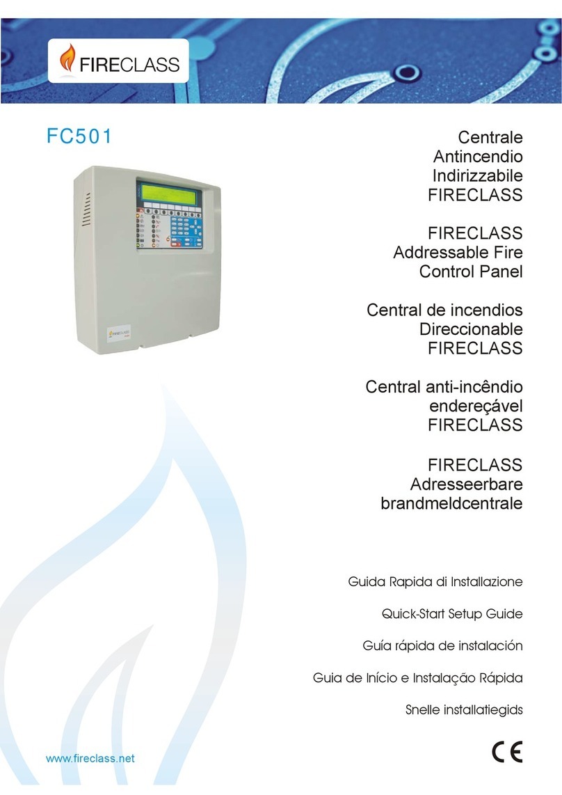
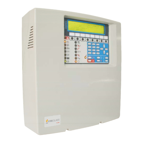
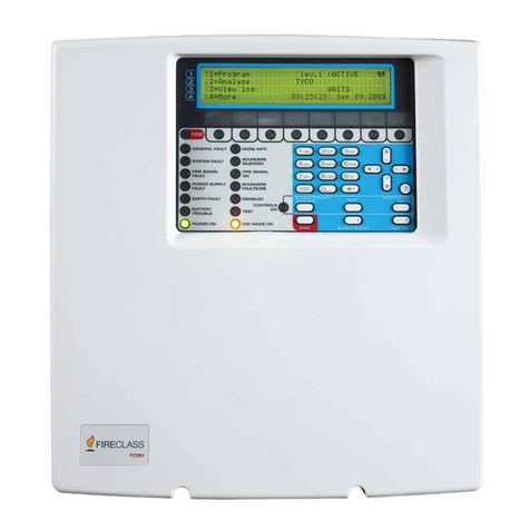
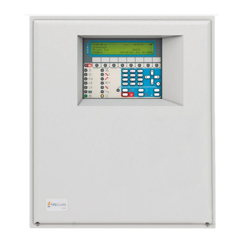
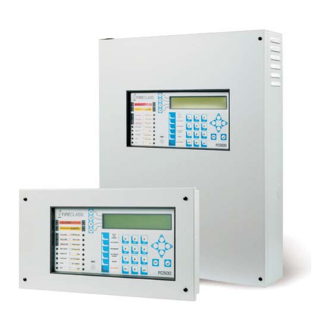
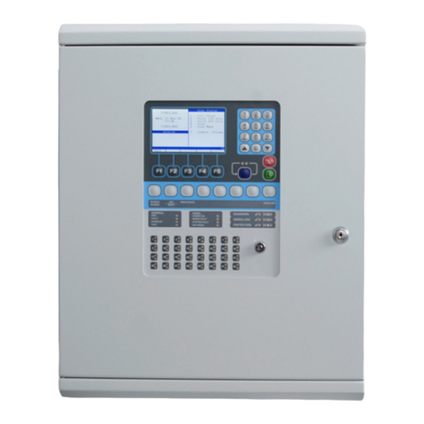
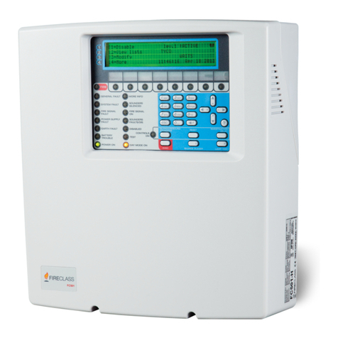
FireClass FC503 Technical manual

1
FC503 & FC506
FIRECLASS
Addressable Fire
Control Panels
Quick-Start Setup Guide
Doc. Version 1.0
06 June 2019
www.fireclass.net

2
Table of Contents
Important notes .................................................................................................................................................................3
Box contents......................................................................................................................................................................5
Cable requirements...........................................................................................................................................................5
Cable types....................................................................................................................................................................5
Earthing .........................................................................................................................................................................5
Screening.......................................................................................................................................................................5
Cable routing.....................................................................................................................................................................5
RS485 networking.............................................................................................................................................................5
Mains supply .....................................................................................................................................................................5
Installation.........................................................................................................................................................................6
Installing the control panel.............................................................................................................................................6
Pre-commissioning checks ...............................................................................................................................................8
Installing the batteries.......................................................................................................................................................9
Commissioning..................................................................................................................................................................9
Panel Checks ................................................................................................................................................................9
HELP key.....................................................................................................................................................................10
Auto-Addressing procedure.........................................................................................................................................10
Auto-addressing notes:............................................................................................................................................11
Programming devices addresses using the programmer............................................................................................12
Adding text and zone information without software.....................................................................................................13
Testing and monitoring the devices.............................................................................................................................13
Testing the local and loop sounders........................................................................................................................13
Testing the open sounder circuit monitoring............................................................................................................13
Testing the short sounder circuit monitoring............................................................................................................13
WALK TEST procedure...............................................................................................................................................13
Useful menu options .......................................................................................................................................................14
Accessing the event log...............................................................................................................................................14
Loop check ..................................................................................................................................................................14
Viewing the device status............................................................................................................................................14
Disabling points...........................................................................................................................................................14
Disabling sounders......................................................................................................................................................14
Loading a language from the USB stick......................................................................................................................14
CPR Information..............................................................................................................................................................16

3
FIRECLASS Addressable Fire Control Panel
Quick-Start Setup Guide
This document has been designed to guide you through the basic installation and setup process for FC503 and
FC506 control panels. Full reference Installation and User manuals are available in the USB drive with all panels or
can be downloaded from our website at www.fireclass.net
The manufacturer reserves the right to change the technical specifications of these products without prior notice.
Important notes
FC503 and FC506 fire control panels
The FC503 and FC506 fire control panels follow Johnson Controls’ highest standards of quality and performance.
FC503 is an analogue addressable fire control panel with one main loop (three sub loops), that can support up to 250
addressable devices and 32 zones. Loop lengths are to be a maximum of 2 km (dependent on device types, quantities
connected, and cable type).
FC506 is an analogue addressable fire control panel with two main loops (six sub loops). The panel can support up to
500 addressable devices and a maximum of 250 devices in a single main loop, and 32 zones. Loop lengths are to be
a maximum of 2 km (dependent on device types, quantities connected, and cable type).
A maximum of 8 nos. of FC500 repeaters, 4 nos. of FC500MFI modules and 7 nos. of Client panels can be driven
from a FC503 or FC506 addressable panel. The Loop devices can be addressed and configured from the panel menu.
See the Auto-Addressing procedure section.
Alternatively, the FC490ST service tool can be used to address your field devices.
WARNING
Read this section completely before
commencing installation.
The control panel must be installed by competent engineers familiar with the installation of fire detection systems. In
addition, it is recommended to refer to the following information:
The current edition of the local laws regarding wiring regulations.
Fire detection and alarm systems in buildings or the installation standards for the relevant country.
Any specific site requirements.
FireClass field device installation instructions

4
Figure: 1 Schematic diagram for typical system layout
DET
Addressable detector
DET*
Conventional detector
IB
Isolator base
CP
Call point
DIM
Detector input module
RIM
Relay interface module
CIM
Contact input module
LI
Line isolator

5
Box contents
The control panel is contained in a box. See the
contents below:
•A sheet metal cabinet and plastic door with an
assembled motherboard and power supply switching.
•The Quick-Start Setup Guide.
•A transparent plastic bag containing a USB consisting
of installation manuals, user manuals, and the FireClass
software console to manage the panel, the KST thermal
probe, two 3.9 kOhm resistors, a 320 mm red and a
black cable with a faston terminal to connect batteries
with main board, and a 320 mm black cable with two
faston terminals to connect batteries.
Proceed carefully to unpack the contents and dispose
of recyclable materials in accordance with local laws.
Cable requirements
All cables should be specified and installed to meet the
requirements of local laws. See Figure: 1 for a typical
system layout.
Cable types
For specific details on the cable types, and how they
should be run, refer to local practices and regulation.
Earthing
The addressable loop conductors must be isolated
from the earth. Any current leakage to the earth is
indicated as a fault.
Screening
If a cable with a conductive screen or a metal sheath is
used, do not connect it to the addressable loop
conductors. Join the screens from each section of the
cable within each loop device to form a continuous
cable screen.
Cable routing
Ensure cables are routed to minimize coupling effects.
Avoid grouping power and signal cables together in the
same conduit or trunking. Feed the mains supply into
the cabinet through its own dedicated knockout.
RS485 networking
Use copper cabling for the network. The maximum
distance between nodes is 1000 m using a shielded
twisted pair cable. Use shielded cables only, with one
end of the shield connected to the control panel
negative terminal and one end of the shield left free.
The continuity between several segments of
connection must be secured.
Mains supply
Do not allow the power cable to cross over other
wiring. The power cable must be routed and held firmly
in place by a two cable tie. The mains supply final
circuits to all parts of the fire alarm system should be
dedicated solely to the fire alarm system, and should
serve no other systems or equipment.
To facilitate local isolation during maintenance,
suitable means should be provided for double pole
isolation of the low voltage supply circuit that serves
the power supply and control equipment.
The power circuits of this control panel comply with the
EN54-4 standard.
CAUTION
In order to comply with the safety
regulations in force, the mains must be
equipped with a bipolar isolating device
for protection against over voltage and
short-circuit to earth.
The control panel is powered from the mains (230 V~
60/50 Hz -15/+10%) and provides housing for a 5.5 A
switching power supply (BAQ140T24).

6
Installation
CAUTION
Installation of the control panel must
take place strictly in accordance with
the instructions in this guide and in
compliance with the local laws and
bylaws in force.
Prior to commencing the installation of the control
panel, take adequate precautions to prevent damage
to the sensitive electronic components on the display
board and control board due to electrostatic discharge.
Discharge any static electricity accumulated by
touching a convenient earthed object such as an
unpainted, copper radiator pipe. Repeat the process at
regular intervals during the installation process.
Installing the control panel
Work carefully through the following steps. See FC503
& FC506 Addressable Fire Control Panels Installation
Manual for further information. Install the FC500IP
module before mounting the control panel as
described in the Installing the FC500IP board section
in the FC503 & 506 Addressable Fire Control Panels
Installation Manual.
CAUTION
Place the panel in a clean, dry
position where there is no shock or
vibration present, and at least 2 m
away from pager systems or any
other radio transmitting equipment.
Separate the fire alarm cables from
all other wiring unrelated to the fire
alarm system.
1. Identify a suitable mounting location on the wall
for the control panel.
2. Remove the two screws from the cover and open
the control panel. Lift the lower part of the cover
and push upwards to fully remove the cover from
the panel assembly.
3. Disconnect the earth cables at the top left and
right of the control panel chassis.
4. Remove the chassis, including power supply and
control board, from its fixings by unscrewing the
screws on the chassis. Remove the top left and
right screws completely. Push the chassis
upwards and remove. Do not remove the power
supply or control board from the chassis. Handle
the chassis carefully to avoid damage and place it
safely to one side.
5. Level and hold the empty cabinet up to the wall.
Mark the positions for the four mounting holes on
the wall.
6. Drill the holes at the marked positions on the wall.
Check for water pipes and electrical wiring before
drilling.
7. Insert the top two screws halfway. Hang the panel
on the top two screws and tighten them securely.
8. Insert the bottom two screws and tighten them
securely.
9. Refit the chassis using the two resting features at
the bottom of the cabinet and the top two
mounting screws.
10. Reconnect the earth lead to the chassis.
11. Insert the installation cables into the cabinet using
the cable entry knockouts at the top of the
cabinet. Use the knockouts for all the cables and
secure the cables through the cable ties.
12. When the installation cabling is complete, check
the cabling to ensure that it is free from short
circuits, open circuits, earth faults, and crossed
connections.
13. Program the control panel in accordance with the
instructions in the FC503 & FC506 Addressable
Fire Control Panels User Manual and the FC503
& FC506 Addressable Fire Control Panels PC
Programming Manual.
14. Test the entire system. Ensure that you test the
control panel, detectors, fire warning, and fire
control devices.
15. Remove any debris from the cabinet before
closing the cover.
16. Attach the cover to the hooks and rotate the cover
down to close it. Secure the cover at the bottom
with two screws.
Note: An identification label of the SW zones is
included on the bottom of the last page of this guide.
Cut the identification label out and insert it in the
pocket of the user interface.

7
Figure 2: Chassis mounting details
1
Mounting studs
2
Mounting slots

8
Figure 3: Cabinet dimension details
Note: All dimensions are in mm.
1
Mounting holes
Pre-commissioning checks
Create temporary connections to test the wiring for
continuity and insulation.
Complete the following steps for pre-commissioning
checks:
1. Run the loop wiring around the building and
wire up the detector bases according to the
system plan or design.
2. Run any other wiring required for ancillary
modules.
3. Label the “+” and “-” conductors and connect
them to the corresponding terminals of the
detector bases.
Where screened cables have been used and
no earth connections are provided at the
device, join the loop screen connections
together using terminal block connector to
maintain the integrity of the loop earth.
CAUTION
Do not wire in any isolator bases and
modules or fit the detectors until pre-
commissioning checks are complete. The
items will be damaged by any high
voltage insulation checks performed. Use
terminal block connectors for any
temporary connections to preserve
continuity. Details for wiring individual
devices are provided with the items.
Do not make the final connections at the
control panel. Testing the wiring requires
access to the free ends of the wires.
4. Pull the cables through the appropriate
knockouts of the control panel. Use glands as
appropriate and leave generous free ends of
the wires.
5. Connect the loop free ends of the wire to a
terminal block connector. Place loosely in the
cabinet to avoid accidental connection to the

9
panel before pre-commissioning checks are
complete.
6. If any conventional sounder circuits are
running, check that all devices have the
correct polarity, that the correct polarity is
maintained, and that the 3.9 Kohm end of the
line resistor has been fitted within the last
device of the circuit.
WARNING
Danger of damage to equipment:
Before using a high-voltage insulation
tester, ensure that no devices liable to
be damaged are fitted to the circuit.
This includes isolator bases and
ancillary modules.
Notes:
Ensure that the insulation check, the cabling
resistance check, and all other necessary
checks comply with current local laws.
Ensure that the mains earth is connected to
the safety earth bar located in the upper part of
the panel cabinet.
Installing the batteries
WARNING
The standby batteries can deliver high
current presenting danger of injury and
equipment damage while working on
the panel. Take care not to accidentally
short the battery terminals.
The suitable batteries for the FC503 and FC506
control panels are two 12 V/17 Ah or two 12 V/ 38 Ah
batteries. The control panel can be connected to the
12 V/38 Ah batteries in an external metal box for
power in the event of a mains failure.
Complete the following steps to install the batteries:
1. Locate the 12 V/17 Ah backup batteries at the
bottom of the panel cabinet and secure them
to the panel cabinet with the battery clamp.
2. Connect the batteries in series with the
supplied 320 mm black battery cable.
3. Connect the battery terminals to terminals –
BAT+ on the main board. Observe the battery
polarity.
4. Connect the KST thermal probe to the
dedicated connector on the switching power
supply. Attach the probe to one of the batteries
to obtain optimum heat transfer. The KST
thermal probe optimizes the battery charging
process by regulating the charge voltage in
accordance with the battery temperature.
Commissioning
Commissioning includes configuring and testing the
system. A fully comprehensive test procedure cannot
be provided because the testing must be in
accordance with local regulations and practice and
sites differ in terms of the system design. Tests must
be individually planned to suit the specific site
requirements. Instead of a comprehensive test
procedure, this section provides guidelines in the form
of an example procedure.
For details of the control panel operator functions, refer
to the FC503 & FC506 Addressable Fire Control
Panels User Manual.
Panel Checks
Complete the following steps to make the panel
checks:
1. Power on the control panel.
If there are panel faults, the internal buzzer will
sound. To temporarily silence the buzzer, press
the SILENCE BUZZER key. Press the ESC key
on the user interface to return to the main menu.
To silence the buzzer for the duration of the
installation, engage the control panel at access
level 3 and remove the Jumper J5.
When the buzzer is disabled, the control panel
user interface zonal LEDs flash and the time, date,
and BUZZER OFF are displayed alternatively. The
timeout for the installer access is not changed as a
result of this procedure.
To reactivate the buzzer, replace the Jumper J5
when the installation process is complete.
2. Using the LAMP TEST key, check that the
LEDs and buzzers function properly. If the
control panel is functioning as intended, all
LEDS will be on and the buzzer emits a
continuous beep.
3. Check the brightness and contrast of the LCD
display. The keys have the following functions:
Up key: increases the brightness of the
LCD display.
Down key: decreases the brightness of
the LCD display.

10
Right key: increases the contrast of the
LCD display.
Left key: decreases the contrast of the
LCD display.
4. Set the date and time on the user interface.
Ensure that the date and time are correct for
log file consistency.
To set the data and time, complete the
following steps:
a. Enter the user access password. Each digit
will be masked by an asterisk and the default
user password is 11111.
b. Press the 3key to select the Modify option on
the MAIN screen.
c. Press the 4key to select Time and Date.
d. Use the alphanumeric key to enter the Time
and Date values. The keys have the following
functions:
Right key: selects the next value to be
inserted or modified.
Left key: selects the previous value to be
inserted or modified.
ENTER key: confirms the TIME and
DATE.
ESC key: returns to the previous screen.
5. Set the system language of the user interface.
To set the system language, complete the
following steps:
a. Press the 1 key to select the Program option
on the MAIN screen.
b. Enter the installer password and press
ENTER. Each digit will be masked by an
asterisk. The default installer password is
00000.
c. Press the 8key to select System LANGUAGE.
The keys have the following functions:
Right key: selects the next language.
Left key: selects the previous language.
ENTER key: confirms the language
selection.
HELP key
An embedded help feature is available on the panel
LCD display. Press the HELP key to see the
dedicated help text for the active User Interface
screen.
Auto-Addressing procedure
Auto-addressing allows you to make all of the devices
accessible from the panel without the need to execute
any previous configuration action on the devices,
during the installation phase or the device acquire
phase. The FC490ST is no longer required for the
manual assignment of the device addresses.
Auto-addressing allows you to know or to set the
geographical position of the devices on the site in the
device mapping phase. The auto-addressing
procedure is part of the loop devices enroll process in
the FC503 panel. Refer to the Quick Start Procedure
section in the FC503 & FC506 Addressable Fire
Control Panels Installation Manual.
To initiate the loop devices enroll process, complete
the following steps:
1. Press the 1key to select the PROGRAM
option on the MAIN screen.
2. Enter the installer password and press
ENTER. Each digit will be masked by an
asterisk. The default installer password is
00000.
3. Press the 1key to select Auto.
Note: If any loop fault such as open circuit or a
double address is detected during the enrolling
phase, the control panel display shows the
instructions to fix it. Refer to FC503 & FC506
Addressable Fire Control Panels Installation
Manual.
4. Choose the type of automatic zones
assignment. The options for automatic zones
assignment are:
1: According to the loop
2: According to the addresses of the
devices
3: Do not assign. When this choice is
made, you can reach the results phase
by:Pressing the ENTER key to activate
the AUTO- ADDRESSING phase
or
Pressing the ESC key to go to the
FAULT screen (not addressable
devices).
5. Choose the sounder trigger event. The options
for the sounder trigger event are:
1: Zone alarm
2: Panel alarm
Note: Once you select an option, the panel
executes the enrolling of already addressed
devices and enters the auto-addressing phase.
6. Press the ENTER key to activate the auto-
addressing phase or ESC key to exit.
By default, any addressable device has the address
255. The fire panel examines the serial number of
each device and assigns each an address from 1 to
250.
If the control panel finds a device with a different
address than the default, it leaves the address set at
that device.

11
The control panel is ready to work, at this time, with
the default basic programming.
If you want to set the system addresses differently,
proceed as follows:
1. Press the ENTER key, so the fire panel
initiates the MAPPING DEVICES phase.
2. Activate all of the input devices in sequence.
The input devices may include detectors, input
modules, and manual call point. Return to the
front of the panel.
3. Report the sequence of activation on the map
of the system. The panel will store the
activation sequence.
4. Use the Up and Down keys to examine the
first activated device. Select the device. When
the device is selected, the address will blink. If
necessary, change the address. Press ENTER
to confirm and the address will be fixed. To
switch to the programming phase of the
device, press the ENTER key again.
Note: Unique in the time field indicates that it
is the only device of its type on the loop. For
example, if only one FC410DDM module is
used in the system, it is tagged as Unique and
it is not necessary to activate it because you
know where it is.
5. Examine the sounders, the beacons, and the
output devices. Locate the devices by
scanning the list of auto-addressed devices.
When you reach an output-only device, it
becomes active. Activation is signaled by a
sounder starting to sound, a beacon starting to
flash, or an output module illuminating its LED.
The device will remain active until a new
device is selected or a permanent address is
entered.
Note: Active in the time field indicates that the
relevant device is active. Active is only
applicable to output device types such as
sounders or beacons.
Auto-addressing notes:
The enroll process does not take place until all the
loop wiring issues have been resolved.
Use the auto-addressing procedure when there
are NG1 devices on the loop or it has no effect.
The device mapping process does not take place
until all of the double address faults have been
removed.
FC506 supports 500 devices and has two logical
loops which each support 1 to 250 devices.
Complete auto-addressing for logical loop1 before
proceeding with auto-addressing for logical loop2.

12
Figure 4: Programming option AUTO
Programming devices addresses using
the programmer
Use the FC490ST service tool to program devices on a
loop as an alternative to auto-addressing.
Complete the following steps to program the device
addresses with the FC490ST:
1. Connect the detector to the programmer. If you
need to program a sounder or a module,
connect the programming lead into the AUX
port of the programmer and the other end of
the lead into the device’s programming port.
You cannot address a detector while the
programming lead is plugged in.
2. To switch the programmer on, press and hold
F1.
3. Press F1, F2, F1, F2, F3, and F4 to enter the
password when prompted.
4. Press F2 to enter the address program. The
current address of the device will be shown.
New devices will have a current address of
255.
5. Press F2 to select the write menu option.
6. Press F3 and F4 to change the address to the
required address.
7. Press F2 when the correct address is
displayed. The programmer will display a
message “programmed ok” and then show the
next address.
8. Label the device.
13
Adding text and zone information without
software
Complete the following steps to add text and zone
information without software:
1. Press the 1key to select the Program option
on the MAIN screen.
2. Enter the installer password and press
ENTER. Each digit will be masked by an
asterisk. The default installer password is
00000.
3. Press the 2 key to select Device.
4. Select the loop by using the Right and Left
cursor keys and press ENTER.
5. Select the device by using the Right and Left
cursor keys and press ENTER.
6. The control panel will prompt you to indicate if
you want to remove the device. Use the Right
and Left cursor keys to select NO and press
ENTER.
7. Use the alphanumeric keypad to enter the
required text in the dedicated field. Use the
cursor key Up to change the text to capitals
and the cursor key Down to change the text to
lower case. Use the 0key to add a space.
Press ENTER to confirm the text. Press
ENTER again if you do not want to change the
WORKING MODE until the zone number is
highlighted.
8. Use the alphanumeric keypad, to enter the
required zone number and press the ENTER
key to confirm.
9. If a change of the device base is not required,
press the ENTER key. The control panel
resets.
Repeat steps 1-8 for all of the addresses you want to
edit.
Testing and monitoring the devices
Check that each device activates correctly. Use the
one man test facility or complete a live test. Examples
of testing include testing call points by pressing the
Activate key or testing smoke detectors with a smoke
aerosol can.
If the auto-addressing procedure was followed, some
devices will already have been verified.
Testing the local and loop sounders
1. Press the EVACUATE key on the panel to
issue an alarm. Check that the sounder has
operated.
2. After the test, press the SILENCE/RESOUND
key and then press the RESET key.
Note: Be aware of the possible nuisance caused
by the alarms and take any required measures.
Testing the open sounder circuit monitoring
1. Disconnect any EOL resistors or associated
circuits in the system. Ensure that the control
panel reports the appropriate faults.
2. After the test, restore the system to normal.
Testing the short sounder circuit monitoring
1. Replace any EOL resistors or associated
circuits in the system with a short circuit.
Ensure that the control panel reports the
appropriate faults.
2. After the test, restore the system to normal.
WALK TEST procedure
1. Press the 1key to select the Program option
on the MAIN screen.
2. Enter the installer password and then press
ENTER. Each digit will be masked by an
asterisk. The default installer password is
00000.
3. Use the 3key to select the SW Zone screen.
4. Select the number zone and press ENTER.
5. Use the Right and Left cursor keys to select
an option. The keys have the following
functions:
OFF: does not perform the procedure.
ALL: selects all the devices assigned to zones
in WALK TEST mode. It will not generate an
alarm in the case of their activation but will
reach the TEST status.
DET: selects only the detectors assigned to
zones in WALK TEST mode. It will not
generate an alarm in the case of their
activation but will reach the TEST status.
CP: selects only the call-points assigned to
zones in WALK TEST mode. It will not
generate alarm in the case of their activation
but will reach the TEST status.
6. Press the ENTER key to confirm the selection.
The presence of a zone in WALK TEST mode is
signaled by the TEST yellow LED on the user
interface. More than one zone can be put in WALK
TEST mode at the same time.

14
Useful menu options
Accessing the event log
Complete the following steps to access the event log:
1. Press the 1key to select the Analyze option on
the MAIN screen and then press the 8key to
select Log. Alternatively, press the 3key to
select View Log.
2. Use the alphanumeric keypad to select the
visualization of the filters. The selection allows
you to observe only a certain type of event.
The options are:
1: Alarm events only
2: Delay to alarm events only
3: Warning events only
4: Test events only
5: Fault events only
6: Restore events only
7: Generic events only.
3. Use the Right and Left cursor keys to scroll
through the data blocks and use the Up and
Down cursor keys to scroll through the events.
Loop check
Complete the following steps to check the loop:
1. Press the 1key to select the Analyze option on
the MAIN screen.
2. Press the 1key to select Loop.
3. Use the Up and Down curser keys to select
the loop to view. The panel will check both
sides of the loop before displaying the
configuration of the loop.
4. To return to the MAIN screen, press the ESC
key.
Viewing the device status
Complete the following steps to view the device status:
1. Press the 1key to select the Analyze option on
the MAIN screen.
2. Press the 2key to select Device.
3. Use the Right and Left cursor keys to scroll
and then press the ENTER key to select the
loop.
4. Press the ENTER key to view all the devices.
5. Use the Right cursor key to select the next
device and use the Left cursor key to select
the previous device.
6. To return to the MAIN screen, press the ESC
key.
Disabling points
Complete the following steps to disable a point:
1. Press the 2 key to select the Disable option on
the MAIN screen.
2. Enter the user password and press ENTER.
Each digit will be masked by an asterisk. The
default user password is 11111.
3. Press the 2key to select Device.
4. Use the Right cursor key to select the next
available device and the Left cursor key to
select the previously available device. Press
the ENTER key to confirm the selected device.
5. Press the ENTER key to confirm the request to
Disable or press the ESC key to return to the
MAIN screen.
Disabling sounders
Complete the following steps to disable a sounder:
1. Press the 2 key to select the Disable option on
the MAIN screen.
2. Enter the user password and press ENTER.
Each digit will be masked by an asterisk. The
default user password is 11111.
3. Press the 4key to select Output.
4. Use the Up or Down cursor keys to scroll
through the type of output to disable or enter
the SC number. Press the ENTER key.
5. If the sounder is disabled, the panel will
prompt you to enable it and if the sounder is
enabled, the panel will prompt you to disable it.
Press the ENTER key to confirm.
Loading a language from the USB stick
The USB option in the PROGRAM menu activates the
USB programming screen. Use the 7key to select the
USB programming screen. The USB programming
screen includes the following options:
0: Extra
1: Load Audio
2: Save Audio
3: Load programming
4: Save programming
5: FW Upgrade
6: Save LOG
The loaded languages are the languages of the control
panel. The default first language is English and cannot

15
be overwritten. The default second language is Italian
and can be overwritten with another language at the
first panel power-up or at the end of the FW upgrade
process.
The available second language files are contained in a
folder on a USB stick connected to the control panel
before the first power up. At the end of the FW
upgrade process, the panel will start the procedure
Language strings download via USB key to load the
correct version of the required language. See Figure 6.
Figure 5: LCD screens sequence for loading a language
1
Choice of language
Figure 6: LCD screens sequence for downloading language strings from USB key at first panel power-up
1
Language list waiting page
2
List of languages in the USB key

16
CPR Information
NOTES
This product uses the FreeRTOS.org real time kernel.
The FreeRTOS.org source code can be obtained by
visiting http://www.FreeRTOS.org
FreeRTOS LICENSING:
"The FreeRTOS source code is licensed by the GNU General Public License
(GPL) with an exception.
The full text of the GPL is available here:
http://www.freertos.org/license.txt
The text of the exception is available on FreeRTOS official
website: http://www.FreeRTOS.org
- License and Warranty Page
The exceptions permits the source code of applications that use FreeRTOS
solely through the API published on this WEB site to remain closed source,
thus permitting the use of FreeRTOS in commercial applications without
necessitating that the whole application be open sourced. The exception
should only be used if you wish to combine FreeRTOS with a proprietary
product and you comply with the terms stated in the exception itself.”
LwIP LICENSING:
"lwIP is licenced under the BSD licence:
Copyright (c) 2001-2004 Swedish Institute of Computer
Science.
All rights reserved.
Redistribution and use in source and binary forms, with or without
modification, are permitted provided that the following conditions are met:
1. Redistributions of source code must retain the above copyright notice,
this list of conditions and the following disclaimer.
2. Redistributions in binary form must reproduce the above copyright notice,
this list of conditions and the following disclaimer in the documentation
and/or othermaterials provided with the distribution.
3. The name of the author may not be used to endorse or promote products
derived from this software without specific prior written
permission.
THIS SOFTWARE IS PROVIDED BY THE AUTHOR ``AS IS'' AND ANY
EXPRESS OR IMPLIED WARRANTIES, INCLUDING, BUT NOT LIMITED
TO, THE IMPLIED WAR- RANTIES OF MERCHANTABILITY AND FITNESS
FOR A PARTICULAR PURPOSE ARE DISCLAIMED.
IN NO EVENT SHALL THE AUTHOR BE LIABLE FOR ANY DIRECT,
INDIRECT, INCIDENTAL, SPECIAL, EXEMPLARY, OR CONSEQUENTIAL
DAMAGES (INCLUD- ING, BUT NOT LIMITED TO, PROCUREMENT OF
SUBSTITUTE GOODS OR SER- VICES; LOSS OF USE, DATA, OR
PROFITS; OR BUSINESS INTERRUPTION) HOW- EVER CAUSED AND ON
ANY THEORY OF LIABILITY, WHETHER IN CONTRACT, STRICT
LIABILITY, OR TORT (INCLUDING NEGLIGENCE OR OTHERWISE)
ARISING IN ANY WAY OUT OF THE USE OF THIS SOFTWARE, EVEN IF
ADVISED OF THE POSSIBILITY OF SUCH DAMAGE."
The Declarations of Performance can be found on the
product webpage at www.fireclass.net
120.515.922_FC- FC500-QKUSR, Doc. version 1.0, 06 June 2019.
©2019 Johnson Controls. All rights reserved. All specifications and other information shown were current as of document revision
date and are subject to change without notice.
www.fireclass.net
Tyco Fire & Security GmbH, Victor von Bruns-Strasse 21, 8212 Neuhausen am Rheinfall, Switzerland.
0051
Tyco Fire & Security GmbH,
Victor von Bruns-Strasse 21,
8212 Neuhausen am Rheinfall,
Schaffhausen, Switzerland
19
DoP-2018-4260 (FC503/ FC506 with optional
FC500IP module)
EN 54-2:1997+A1:2006 EN54-4:
1997+A1:2002+A2:2006
EN 54-21: 2006
Control and indicating equipment with integrated
power supply equipment for fire detection and
fire alarm systems for buildings with alarm
transmission and fault warning routing
equipment.
EXPECTED OPTIONS
Fault signals from points
Dependencies on more than one alarm signal:
type A and B Delays to outputs
Disablement of
addressable point
Test condition
Output to fire alarm device
Other manuals for FC503
4
This manual suits for next models
1
Table of contents
Other FireClass Control Panel manuals

FireClass
FireClass FC501-HK User manual

FireClass
FireClass Precept EN Panel User guide

FireClass
FireClass FC501 Series Technical manual

FireClass
FireClass 500 User guide

FireClass
FireClass FC501 Series User manual

FireClass
FireClass FC501 Series User manual

FireClass
FireClass FC503 User manual

FireClass
FireClass FC600 User manual

FireClass
FireClass FC500 Owner's manual

FireClass
FireClass FC32-1 Owner's manual