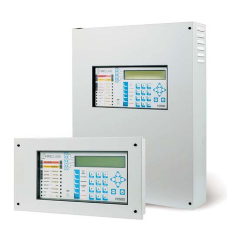
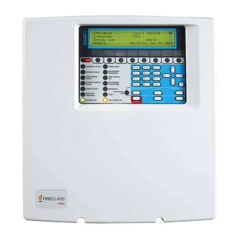
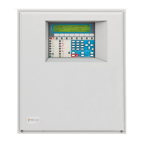
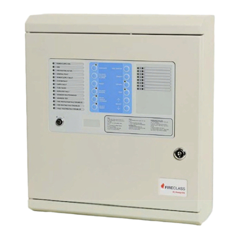
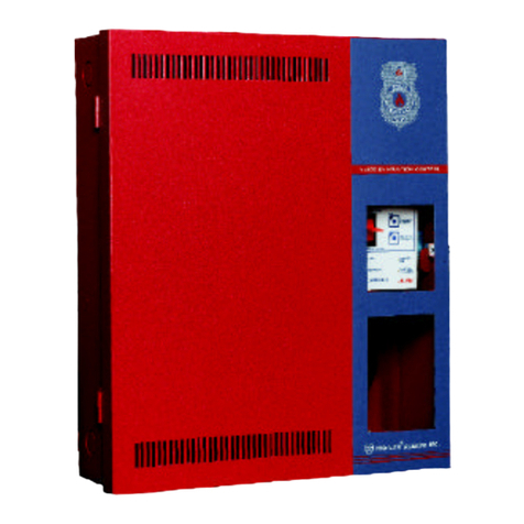
FireClass FC-P-S Installation and user guide

Service and Maintenance
FC-P-S
Doc. version 1
22. March 2012
FireClass
Addressable Fire Alarm
Control Panels
From Software version 21

© FIRECLASS. Hillcrest Business Park, Dudley, West Midlands, DY2 9AP, UK, 2012
Contents subject to change without notice.
All rights to this documentation, including the contents of the online help, are reserved, in particular but not limited to the
rights of copying, distribution and translation.
No portion of this documentation, including the online help, may be reproduced, edited, copied or distributed in any form
without prior written authorization from FIRECLASS. Use of the data medium provided with this product is restricted to cop-
ying the software for the purpose of data backup only.

FireClass Fire detection system FireClass Panels Contents
Service and Maintenance Doc. version 1 3
Contents
1 Introduction..................................................................................................................... 5
1.1 About this Guide............................................................................................................................5
1.1.1 Who this Guide is For ............................................................................................................................................................................... 5
1.1.2 What this Guide Covers........................................................................................................................................................................... 5
1.1.3 What this Guide does not Cover.......................................................................................................................................................... 5
2 Control Panel Functions................................................................................................. 6
2.1 Logging On .....................................................................................................................................6
2.2 Access Levels ................................................................................................................................6
2.3 Using the Menus............................................................................................................................7
2.3.1 Network and Non-Network Addresses ............................................................................................................................................. 9
2.4 Clearing Panel Logs.......................................................................................................................9
3 Menu Details ................................................................................................................. 11
3.1 View Status|Commis. Overview................................................................................................11
3.2 View/Print Data|Loop Info .........................................................................................................11
3.2.1 Loop Point Counters.............................................................................................................................................................................. 11
3.2.2 Loop Point Status ................................................................................................................................................................................... 12
3.3 View/Print Data|Forced Points..................................................................................................12
3.4 Disablements|Non-LED Outputs................................................................................................13
3.5 Service| Maintenance ................................................................................................................13
3.5.1 Diagnostics ............................................................................................................................................................................................... 15
3.5.2 Calibrate DDM ......................................................................................................................................................................................... 16
3.5.3 Restart System......................................................................................................................................................................................... 17
3.5.4 Switches..................................................................................................................................................................................................... 17
3.6 Configuration ...............................................................................................................................18
3.6.1 Change Text.............................................................................................................................................................................................. 18
3.6.2 Insert Point ................................................................................................................................................................................................ 20
3.6.3 Delete Point .............................................................................................................................................................................................. 20
3.6.4 Modify Point.............................................................................................................................................................................................. 20
3.6.5 Autoconfiguration .................................................................................................................................................................................. 21
4 Default System Points.................................................................................................. 22
4.1 Point Type Explanations .............................................................................................................22
4.2 Local I/O (Field Interface Module/CPU) ....................................................................................22
4.3 Rbus ..............................................................................................................................................23
4.4 Addressable Loop........................................................................................................................24
5 Appendix........................................................................................................................ 25
5.1 Fault Finding Information ...........................................................................................................25
5.2 Fault Reporting, Psuedo, Points.................................................................................................25
5.3 Placing Standard Points Into Fault ............................................................................................25
5.4 Psuedo Points In FireClass .........................................................................................................25
5.4.1 Point Section – Local I/O..................................................................................................................................................................... 25
5.4.2 Point Section – RBUS Node Faults .................................................................................................................................................. 29
5.4.3 Point Section – Network Card Faults .............................................................................................................................................. 29
5.4.4 Point Section – COM1 Faults............................................................................................................................................................. 29
5.4.5 Point Section – COM2 Faults............................................................................................................................................................. 30
5.4.6 Point Section – COM3 Faults............................................................................................................................................................. 30

Contents FireClass Fire detection system FireClass Panels
4Service and Maintenance Doc. version 1
5.5 General Fault Overview...............................................................................................................30
5.5.1 Fault Conditions On Devices.............................................................................................................................................................. 30
5.6 System Fault ................................................................................................................................35

FireClass Fire detection system FireClass Panels 1 Introduction
Service and Maintenance Doc. version 1 5
1 Introduction
This section provides an introduction to the guide itself, and
to the products covered.
1.1 About this Guide
1.1.1 Who this Guide is For
This guide is aimed at suitably qualified technicians who are
experienced in the principles of fire detection and alarm
systems, and who have received training in FireClass based
systems.
1.1.2 What this Guide Covers
This guide covers the diagnostic and re-configuration func-
tions of FireClass control panels, as accessed from menu
options. The information is applicable to any memberof the
FireClass range of control panels.
The guide covers, for example, adding detectors to the sys-
tem and changing zone descriptions.
The guide covers version 21 of the control panel firmware.
1.1.3 What this Guide does not Cover
This guide does not provide specific maintenance and serv-
icing schedules, as these are expected to be covered by
local site practices and/or regulations.
This guide does not provide detailed information where this
is covered by another of the guides available for the Fire-
Class range, such as the user guide or the installation guide.

2 Control Panel Functions FireClass Fire detection system FireClass Panels
6Service and Maintenance Doc. version 1
2 Control Panel Functions
The control panel has “normal user” functions, such as
setting the time and date, and viewing the event log. These
functions are covered in the user guide.
The control panel also has “higher level” engineering
functions, such as adding detectors to the system and
changing point addresses. These functions are covered in
this guide.
2.1 Logging On
You need to log on to the panel to access the control panel
functions.
How to log on to the panel
1 Turn the Enable Keyswitch to the ON (I) position.
2 Press the Passcode key (F3).
3 Enter your user ID. You only need to press Enter (F5) if
your ID has only one digit.
If you are already logged on, you see an “open”
message. Press the Back (F1) key.
4 Enter your passcode. For the access levels User and
Supervisor, the number of digits in the passcode must
contain 4 digits. For the access level Engineer, the
number of digits in the passcode must contain 6 digits.
You will need to press Enter (F5) for the login
credentials to be accepted if the passcode is less than 6
digits. You will not need to press Enter (F5) for the login
credentials to be accepted if the passcode is 6 digits.
If another user was logged on, this user is automatically
logged off.
2.2 Access Levels
After logging on you access the functions in the form of
menu options displayed on the LCD.
The “access level” of your user ID will determine which of
the menu options you have access to.
The access levels are as follows:
Covered in this FireClass Service and Maintenance
guide:
– Engineer: Highest access level. Can access all the
menu options that are not available for the user and
supervisor levels.
Covered in the FireClass User guide:
–User
–Supervisor
For each of the normal user menu options, details of the
access level required are provided in the FireClass User
guide (the required level will be User and Supervisor).
For the engineering menu options, the minimum access
levels required are shown in Table 1 (some normal user
options are included for clarity).
CAUTION
After use, do not forget to “log off” by switching
the Enable Keyswitch to OFF (0), and
removing the key. This will prevent
unauthorised access to the panel.
This applies especially if you have an
engineering access level, as there is a longer
inactivity period before automatic log off.
Automatic Log off
You are automatically logged off after a period
of inactivity.
Function See Page Minimum Access Level
View Status menu see User guide No logon needed
Commis. O/View 11 Engineer
Loop Info 11 Engineer
Disablements see User guide User
Non-LED Outputs 13 Engineer
View/Print Data see User guide User
Table 1: Functions and required access levels

FireClass Fire detection system FireClass Panels 2.3 Using the Menus
Service and Maintenance Doc. version 1 10
2.3 Using the Menus
Enable Keyswitch to ON. Press Passcode key (F3). Enter
the User ID and Passcode. Press Enter if the passcode
contains only 4 digits. If the passcode contains 6 digits, the
log in information screen automatically leads to the Main
Menu screen.
You now see the Main Menu shown in Fig. 1. Note how the
Menu key (F1) has been replaced with a Back key, for
exiting menus.
Most of the menu options are only available once you have
logged on. Fig. 1 shows all the options. If you have one of
the lower access levels, you may not see all these options.
Forced Points 12 Engineer
Service menu see User guide Supervisor
Maintenance 13 Engineer
– Counters 13 Engineer
– Maintenance Request 14 Engineer
– Battery Test 14 Engineer
– S/W Init. Count 14 Engineer
–ProjectNumbers 14 Engineer
– Software Versions 14 Engineer
Diagnostics 15 Engineer
–ForceDev.O/P 15 Engineer
–ForceDev.I/P 15 Engineer
– Shutdown/Rstart 16 Engineer
– Single Dev.Poll 16 Engineer
– Change Address 16 Engineer
Calibrate DDM 20 Engineer
Restart System 17 Engineer
Switches 17 Engineer
– Fast Fault Mode 17 Engineer
– Rate of Rise 17 Engineer
– Noisy Device 17 Engineer
– Detect. Power Up 17 Engineer
– RSM Test Mode 18 Engineer
– Inhibit No Resp 18 Engineer
Configuration menu 18 Engineer
Change Text 18 Engineer
Insert Point 20 Engineer
Delete Point 20 Engineer
Modify Point 20 Engineer
Autoconfig. 21 Engineer
Function See Page Minimum Access Level
Table 1: Functions and required access levels (cont.)

2.3 Using the Menus FireClass Fire detection system FireClass Panels
8Service and Maintenance Doc. version 1
Select the menu options by their number (press the
appropriate number key). Each option leads to a further
screen, which may present further options.
Details of the menu screens are provided in section 3
“Menu Details“ on page 11.
In using the menus you always use combinations of the
same basic methods – to navigate between the various
settings in a screen for example. To avoid repetition this
guide does not provide full step by step details for each
screen. Instead, the illustration below serves as an example
of how you use the basic methods. The illustration is based
on discovering the status of a point.
How to discover the status of a point
1 Enter your passcode to display the Main Menu (this is
not strictly necessary when viewing status, and is only
included for the purposes of the illustration):
2 Press the 2key to display the View Status menu:
3Pressthe1key to display the next menu:
4Pressthe1key to display the next screen:
5 In this scenario, the loop setting (A) does not need
changing.
For a 2 or 4 loop configured panel, to change the loop,
highlight the loop setting and press +key to increment
it to the next loop or press -key to move to the previous
loop.
You press the >> key (F2) to move the highlight to the
point field:
Fig. 1: Main Menu
Fig. 2: Main Menu
Main Menu
FireClass
Wed, 17-Aug-11
16:37
High Street Office
1 - Accept Events
2 - View Status
3 - Disablements
4 - Time / Date
5 - Event Log
6 - View/Print Data
7 - Service
8 - Configuration
9 - Test Buzzer,
LEDs & Display
Alarm Count: 0021
General
Flt P 011
Back
Main Menu
FireClass
Wed, 17-Aug-11
16:37
High Street Office
1 - Accept Events
2 - View Status
3 - Disablements
4 - Time / Date
5 - Event Log
6 - View/Print Data
7 - Service
8 - Configuration
9 - Test Buzzer,
LEDs & Display
Alarm Count: 0021
General
Flt P 011
Back
Fig. 3: View Status
Fig. 4: View Status Point Selected
Fig. 5: View Status Loop Highlighted
View Status
FireClass
Wed, 17-Aug-11
10:37
High Street Office
1 - Point
2 - Point I/P only
3 - Point O/P only
4 - Zone
5 - Zone Maps
6 - Network Status
7 - Commis. O/View
General
Flt P 011
Back
View Status
FireClass
Wed, 17-Aug-11
10:37
High Street Office
Point
1 - Loop Point
2 - RBus Point
3 - Local I/O Point
General
Flt P 011
Back
View Status
FireClass
Thu, 18-Aug-11
11:07
High Street Office
Point
Panel
01
Loop Point
001
General
Flt P 011
Back >> - + Enter
A

FireClass Fire detection system FireClass Panels 2.4 Clearing Panel Logs
Service and Maintenance Doc. version 1 10
6 Press the +key (F4) to increment the point number (or
press the 2key):
7 Press the Enter key (F5) to display the point status:
For further options displayed on the View Status Menu,
refer to the FireClass User guide.
2.3.1 Network and Non-Network
Addresses
You will sometimes need to enter an address in the system.
For example, to view the status of a point you specify the
point address, using the type of screen shown in Fig. 9.
In this screen, note the Panel 02 item (panel selection
option). This only applies to a networked system where
each panel has been configured using a network card
(TLI800EN).
In a non-networked system, you do not need to specify the
panel number (as there is only one panel), so the item does
not appear.
In some cases there is a separate screen for specifying the
panel number – again this will not be shown in a non-
networked system.
2.4 Clearing Panel Logs
Clearing the control panel logs simultaneously effects the
following:
Clearing the Event Log.
Resetting the Fire Cycle Count.
Resetting the Software Initialisation Count (The
Software Initialisation Count can also be reset
independently – for details see 3.6.2 “Insert Point“ on
page 20).
Resetting the time and date.
In the procedure below, the bold items are identified with
labels on the controller circuit boards.
Fig. 6: View Status Point Highlighted
Fig. 7: View Status Point Highlighted
Fig. 8: View Status Point
View Status
FireClass
Thu, 18-Aug-11
11:07
High Street Office
Point
Panel
01
Loop Point
A
General
Flt P 011
Back >> - + Enter
001
View Status
FireClass
Thu, 18-Aug-11
14:51
High Street Office
Point
Panel
Loop Point
A
General
Back >> - + Enter
002
View Status
FireClass
Thu, 18-Aug-11
11:27
High Street Office
Point
Zone 01.001 A002
Zone01
Call alarm in room
460PH
General
Flt P 011
Back
Input Output
Normal
Fig. 9: View Status – Panel Number
CAUTION
Possible loss of important historical data.
Only use the resetting option below with care.
View Status
FireClass
Thu, 18-Aug-11
11:27
High Street Office
Point
Panel
Loop Point
A 001
General
Flt P 011
Back >> + - Enter
02

2.4 Clearing Panel Logs FireClass Fire detection system FireClass Panels
10 Service and Maintenance Doc. version 1
How to reset registers
1 Open the front panel of the controller.
2 On the CPU board, fit a link to header H2.
3 Press and hold the switch S1 until the WDOG LED
flashes.
4 Release S1, remove the link from H2.
5 Press and hold switch S1 until the WDOG LED flashes.
6 On the rear of the DCM Display Board mounted inside
the door, press the reset button.

FireClass Fire detection system FireClass Panels 3 Menu Details
Service and Maintenance Doc. version 1 11
3MenuDetails
A typical Main Menu screen is shown in Fig. 10.
In this guide only the “engineering” menuoptions under the
Service and Configuration options are covered. If any menu
option is not described in this guide, the details of that
option are covered in the FireClass User guide.
The sections below detail the menu options.
3.1 View Status|Commis.
Overview
Use this Commis. O/View option for a quick status
overview of the commissioning facilities of the control
panel. You see the type of screen shown in Fig. 11.
Most of the items in the screen relate to the switches – for
details of the options 1-7, see 3.5.4 “Switches“ on
page 17. For details on the option 8: Dis .NonLED Ops see
3.4 “Disablements|Non-LED Outputs“ on page 13.
A “Y” indicates that the mode is enabled.
A “Y” against the “Test Equipment” item indicates that there
is an external test equipment connected to the control
panel. As an example, a PC running the FireClass Checker.
A “Y” against the “Commis. User” item indicates that the
logged on user has the Commissioning access level.
3.2 View/Print Data|Loop Info
Use this Loop Information option to derive details about the
various loop point counters and the status of various points.
This option is accessible only by the Engineer.
3.2.1 Loop Point Counters
Use this Loop Point Counters option to check that the
panel configuration matches the physical state of the loop,
and to see the number of points on the loop.
This option appears abbreviated to Loop Point Ctrs in
the menu.
After specifying the loop name, you see a “please wait”
message until the count is complete.
If no faults are found, the type of screen shown in Fig.12 is
displayed.
The conditions for “passed” are as follows:
The number of configured points equals the number of
detected points on the loop.
Detected points from left, right and both sides are equal.
If not all conditions are met, you see the type of screen
shown in Fig. 13.
Fig. 10: Main Menu
Fig. 11: Commis. O/View
Main Menu
FireClass
Wed, 17-Aug-11
16:37
High Street Office
1 - Accept Events
2 - View Status
3 - Disablements
4 - Time / Date
5 - Event Log
6 - View/Print Data
7 - Service
8 - Configuration
9 - Test Buzzer,
LEDs & Display
Alarm Count: 0021
General
Flt P 011
Back
Commis. Overview
FireClass
Thu, 18-Aug-11
13:27
High Street Office
Panel :01
1-SDevPoll:
2-Lp.Shtdn:
4-Rate of Rise :
5-Fast Fault : Y
6-Device PowerUp :
7-Noisy Device :
8-Dis.NonLED OPs :
Test Equipment :
Commis. User :
General
Flt P 011
Back >>Panel >>
Loop Versions
For a 2- loop panel version, you can make a
choice between the configured loops A and B.
For a 4- loop panel version, you can make a
choice between the configured loops A, B, C
and D.
Fig. 12: Loop Point Counters, Loop
Loop Point Counters
FireClass
Tue, 30-Aug-11
14:51
High Street Office
Counter
Loop : A
P A S S E D
Configured : 010
General
Flt P 007
Back Details Scan

3.3 View/Print Data|Forced Points FireClass Fire detection system FireClass Panels
12 Service and Maintenance Doc. version 1
As you can see, the problem in the screen example is a
missing device.
Details screen
Press the Details key (F2) to see the type of screen in
Fig. 14.
Press the >> key to see more point addresses.
The connection status of each point is indicated by the
following symbols:
OK: point connected, configured and identified
(applies to point 33 and points 60 to 64)
Point was configured but not connected or
identified (applies to point 21)
Point was not configured but connected (applies to
point 6)
Scan screen
Press the Scan key (F3) to see the type of screen shown in
Fig. 15.
Press the >> key to see more point addresses.
The points are shown which were detected from both sides
(Left/Right).
They are displayed as follows:
. Empty (not used)
OK: detected from both sides (applies to points 33
and 82)
Only detected from left side (applies to points 2and
20)
Only detected from right side (applies to points 60
to 63)
3.2.2 Loop Point Status
Use this option to print the statuses of all the points of
different loops that are configured. The screen is displayed
as shown in Fig 16.
3.3 View/Print Data|Forced
Points
Use this Forced Points option to view the number of loop
points that are in the forced state.
Fig. 13: View Loop Point Counters, Attention
Fig. 14: Details
Loop Point Counters
FireClass
Tue, 30-Aug-11
14:51
High Street Office
Counter
Loop : A
A T T E N T I O N
Configured : 010
Conf. & Ident: 009
General
Flt P 007
Back Details Scan
Loop Point Counters
FireClass
Tue, 30-Aug-11
14:51
High Street Office
Details
Loop : A
Point 0123456789
0 : ..........
10 : ..........
20 : ..........
30 : ...o......
40 : ..........
50 : ..........
60 : ooooo.....
70 : ..........
80 : ..........
General
Flt P 007
Back >>
c
u
Fig. 15: Scan
Fig. 16: Loop Point -Print Status
Loop Point Counters
FireClass
Tue, 30-Aug-11
14:51
High Street Office
Left / Right Scan
Loop : A
Point 0123456789
0 : ..........
10 : ..........
20 : . ........
30 : ...*......
40 : ..........
50 : ..........
60 : r.........
70 : ..........
80 : ..*.......
General
Flt P 007
Back >>
l
l
rrrr
Loop Point Status
FireClass
Tue, 30-Aug-11
14:51
High Street Office
PRINT ONLY
All loops
General
Flt P 007
Back Print

FireClass Fire detection system FireClass Panels 3.4 Disablements|Non-LED Outputs
Service and Maintenance Doc. version 1 13
The screen appears as shown in Fig. 17.
3.4 Disablements|Non-LED
Outputs
Selecting this option should disable the Non-LED Outputs
such as the BackLight, Buzzers, Sounders, Alarm Relays
etc.). The screen appears as shown in Fig 18.
The points that are enabled/disabled using this option
remain in that state only in the panel configuration. The
points that are configured on the network do not reflect this
state.
Disable: This option allows you to disable the Non-LED
Outputs.
Enable All: This option allows you to enable the forced,
active and non-active points.
Enable.Not.Actv: This option allows you to enable only
the points that are not currently in the active state.
3.5 Service| Maintenance
Use this Maintenance option to see maintenance type
information. Fig. 19 shows the type of screen that will be
displayed.
Counters
Use this Counters option to see the number of times an
alarm event has occurred (Fire Cycle). Fig. 20 shows the
type of screen that will be displayed.
Resetting this count is not a user function. This count is not
reset by a loss of power or system resets.
Site Test appears only when the panel is in a network.
Local test counter counts the total number of devices
which have been walk-tested since panel installation.
When the count exceeds 64000, the count displays
64000+.
Site test counter counts the total number of devices
which have been walk-tested site-wide (all panels in the
network). When the count exceeds 99999, the count
displays 99999+.
Forced State
For information on how to place a loop point in
the forced state refer to the option “Force
Dev.O/P” and “Force Dev.I/P”.
Fig. 17: Forced Points
Fig. 18: Non-LED Outputs
Points Forced
FireClass
Wed, 31-Aug-11
14:51
High Street Office
Input
Total: 2
Zone 01.001 A001
PhotoSensor Device
----------------------
Zone 02.002 A002
Heat Device
General
Flt P 011
Back Output Print
Disablements
FireClass
Tue, 16-Aug-11
11:51
High Street Office
Non-LED Outputs
Disables all
Non-LED outputs
Point changes not sent
to network.
1 - Disable
2 - Enable All
3 - Enable Not Actv
General
Flt P 009
Disbd 002
Back
Disablements count
When disabling, you may see a Matches and a
Successes number indicated.
For example you might use any of the 3
options (Disable, Enable All and
Enable.Not.Act) and see:
Matches 24
Successes 23
Here Matches is the number of units (Non-LED
Outputs) which were liable to be disabled, and
Successes is the number of units that actually
became disabled (the two numbers being
different because a Non-LED Output was
already disabled).
Fig. 19: Maintenance
Maintenance
FireClass
Thu, 18-Aug-11
15:27
High Street Office
1 - Counters
3 - Maint. Request
4 - Battery Test
5 - S/W Init Count
6 - Project Numbers
7 - S/W Versions
General
Flt P 011
TestZ 001
Back

3.5 Service| Maintenance FireClass Fire detection system FireClass Panels
14 Service and Maintenance Doc. version 1
Maintenance Request
This option is abbreviated to Maint. Request in the menu.
Use this option to see a list of detectors which are near the
limit of their threshold compensation limit. Fig. 21 shows
the type of screen that will be displayed.
Battery Test
Use this Battery Test option to see the state of the battery.
Fig. 22 shows the type of screen that will be displayed.
S/W Init. Count
Use this S/W Init. Count (Software Initialisation Count)
option to see a count of the operating program restarts, and
to reset this count.
Press the Reset key (F5) key to set the count back to 1.
Project Numbers
Use this Project Numbers option to see information
relating to the configuration of the panel (the project
information and FireClass Express information). Fig. 24
shows the type of screen that will be displayed.
Software Versions
The option appears abbreviated to S/W Versions in the
menu. Use this option to see the version number of various
items, such as the firmware and bootrom.
A screen of the type shown in Fig. 25 is displayed (includes
details on the network card, if fitted).
Fig. 20: View Fire Alarm Cycle Count
Fig. 21: Maintenance Request
Fig. 22: Battery Test
COUNTERS
FireClass
Thu, 18-Aug-11
11:27
High Street Office
Fire Cycle :0000
Local Test :00000
Site Test :00000
General
Flt P 011
TestZ 001
Back
Maintenance Request
FireClass
Thu, 18-Aug-11
15:48
High Street Office
Total : 003
Zone 002 B002
Zone 004 A126
Zone 008 B006
General
Flt P 011
TestZ 001
Back Print
Battery Test
FireClass
Thu, 18-Aug-11
15:58
High Street Office
Battery State :
Battery OK
Battery Voltage :
26.124 V
General
Flt P 011
TestZ 001
Back
Fig. 23: S/W Init Count
Fig. 24: Project Numbers
Software Init Count
FireClass
Thu, 18-Aug-11
16:28
High Street Office
–Firmware 06
General
Flt P 011
TestZ 001
Back Reset
Project Numbers
FireClass
Thu, 18-Aug-11
15:48
High Street Office
Project:
Acme Head Office
Base Template:
FC21.PJQ
FCExpress: V21.0
Revision : 11
Created:
02-Aug-11 10:18
Downloaded:
15-Aug-11 15:20
General
Flt P 011
TestZ 001
Back

FireClass Fire detection system FireClass Panels 3.5 Service| Maintenance
Service and Maintenance Doc. version 1 15
Press +(F2) for additional details of the software versions.
3.5.1 Diagnostics
Fig. 26 shows the options in the Diagnostics menu.
Force Dev.O/P
Use the Force Device Output option to activate an
output point, causing a sounder to sound, for example.
Choose the type of point and specify the address. You then
see the type of screen shown in Fig. 27.
Press the number key (1to 4) appropriate to your required
operation. For example press 1key to force the point ON.
The available operations now change.You will see a
9 - Unforce option if the device is forced, for example.
The Force OFF option prevents the device activating
when it normally would. For example a forced off sounder
would not sound when the panel went into alarm.
If you displayed the status screen for the point, it would
show the forced status of the point (such as “Forced ON”).
You can navigate away from the Force Device Output
screen, and on navigating back it will still be in the same
state. You could navigate to another point and also force
this.
Resetting the control panel also unforces any forced points.
Force Dev.I/P
Use the Force Device Input option to simulate the
activation of an input device, such as a detector.
Choose the type of point and specify the address. You then
see the type of screen shown in Fig. 28.
Press the 1key to force the point.
The control panel will now respond as if the device at the
point had activated. For example forcing a detector will
probably put the control panel into an alarm state.
Fig. 25: Software Versions
Fig. 26: Diagnostics Menu
Fig. 27: Force Device Output
Software Versions
FireClass
Thu, 18-Aug-11
15:48
High Street Office
Firmware V21.0
Bootrom V1.2
Local I/O V1.0
Loop A V6.0
Loop B V6.0
OCM00 V2.0
OCM01 V2.0
General
Flt P 011
TestZ 001
Back +Print
Diagnostics
FireClass
Thu, 18-Aug-11
16:48
High Street Office
1 - Force Dev.O/P
2 - Force Dev.I/P
3 - Shutdown/Rstart
6 - Single Dev.Poll
7 - Change Address
General
Flt P 011
TestZ 001
Back
Force Device Output
FireClass
Thu, 19-Aug-11
11:47
High Street Office
Zone 003 A005
Zone 03
Sounder Device
SAB 800
Status: Unforced
1 – Force ON
2 – Force Pulse 1
3 – Force Pulse 2
4 – Force OFF
General
Flt P 011
TestZ 001
Back
CAUTION
When forcing points there is a
possibility of raising a false alarm.
Take the appropriate steps to prepare
for this, such as issuing a warning.
Disable Devices
The Force OFF option is not used to disable
devices. To disable devices, see the option
Disablements in FireClass User guide.
Fig. 28: Force Device Input
Force Device I/P
FireClass
Thu, 19-Aug-11
11:47
High Street Office
Zone 006 A007
Zone 06
Photo Sensor Device
FC460 PH
Status: Unforced
1 – Force ON
General
Flt P 011
TestZ 001
Back

3.5 Service| Maintenance FireClass Fire detection system FireClass Panels
16 Service and Maintenance Doc. version 1
The “View Status” screen for the point will now show
Forced ON.
The Force Device Input screen will now show the
9 - Unforce option for unforcing the device. (This also
applies if you navigate away from this screen then navigate
back. You could navigate to another point and the forced
condition is still maintained).
Resetting the control panel also unforces any forced points.
Shutdown/Rstart
Use the Shutdown/Rstart option to close down
complete loops. All power and signalling is shut down,
allowing maintenance to be carried out on the loop without
having to shut down the complete control panel, for
example.
Also use the option to subsequently re-start the loops.
After navigating to the loop press the appropriate number
key for 1 - Shutdown or 2 - Restart.
The status message is displayed as ‘Successful’.
You can navigate away from the Shutdown/Restart screen
and when you return it will be in the same state.
Single Dev.Poll
Single Device Polling is abbreviated as S.Dev Poll or
Single Dev.Poll. Use this option to limit the polling of
devices to one specified device.
This can be useful, for example, in identifying detectors. You
would specify the detector you want to identify, and this
detector will then be the only one that has a flashing LED.
(All other detectors will have an inactive LED.)
After selecting this Single Dev Poll option, enter the
address of the device you want to poll. Then press the
Start key (F4).
To end the polling press the End key (F5).
You can navigate away from the Single Device Polling
screen, then back again, before pressing the End key. The
polling continues until you press the End key. You cannot
select another device to poll until you have pressed the End
key.
Change Address
You mainly use the Change Address option when
replacing a faulty device, using the procedure below (for
example).
To replace a faulty device
1 Remove the faulty device from its base, replacing it with
a new one.
2UsethisChange Address option, to display the type
of screen shown in Fig. 29.
3 For the Old Address, enter the address of the new
device. For newly manufactured devices this will be the
factory set default of “255”.
4FortheNew Address, enter the address of the
replaced faulty device.
The new device will now have the address of the replaced
device.
3.5.2 Calibrate DDM
This Calibrate DDM option is for use when a loop features a
conventional detector circuit, and the conventional circuit
uses diode bases and the conventional circuit is interfaced
using a FC410DDM.
In such a configuration the removal of a detector can be
sensed, through the resulting change in circuit parameters.
The calibrate option identifies the initial correct circuit
parameters, against which the change can be detected.
CAUTION
When forcing points there is a
possibility of raising a false alarm.
Take the appropriate steps to prepare
for this, such as issuing a warning, or
disabling the signalling equipment.
DANGER
Using Single Device Poll may lead to a
failure or delay in detecting fires
leading to possible death, serious
injury or damage to property.
This is because detectors will be
disabled by using the option. Use with
caution, and only for as short a time as
possible.
Fig. 29: Change Address
Change Address
FireClass
Thu, 19-Aug-11
11:17
High Street Office
Old Address : 255
Type : 460 PH
New Address :
General
Flt P 011
TestZ 001
Back - + Enter
3

FireClass Fire detection system FireClass Panels 3.5 Service| Maintenance
Service and Maintenance Doc. version 1 17
Use Calibrate DDM under the following circumstances:
On initial commissioning.
When changes have been made, such as changing
detector types, adding detectors or changing the
wiring.
After selecting Calibrate DDM, specify the Panel, Loop
and Point address of the FC410DDM.
Alternatively, leave one or both of these set to All, to
calibrate a range of FC410DDM devices as shown in
Fig. 30.
Now press Enter.
3.5.3 Restart System
Use this Restart System option to restart the panel with
the configured changes.
3.5.4 Switches
Use the Switches option to switch various modes off or
on.
For each mode there is a screen for making the switch. On
switching, the screen changes to show the prompt for
switching back again.
You can navigate away from the screens, then back again,
without changing the prompt (so your setting remains in
force until you change it).
Fast Fault Mode
Use Fast Fault Mode to reduce the delay between faults
occurring and being reported. You could use this mode to
speed up testing – you might be removing detectors and
checking the panel registers this as a “no response” fault,
for example.
Normally faults must be present for one minute before they
are reported. This is to prevent spurious faults, caused by
electrical noise on the addressable loop for example.
With the display showing Status: Std Fault, press the 1
key to switch to Status: Fast Fault. Press the 2key to
switch back.
In “Fast Fault” faults are reported immediately. That is on
the first detector poll that discovers them (or within three
polls for certain devices).
Rate of Rise
With the display showing Status: ON, press the 2key to
switch to Status: OFF. Press the 1key to switch back
again. It is used on certain types of fire detectors to detect
the heat generated and not smoke.
Noisy Device
Detectors showing large variations in values can trigger a
“noisy device” fault indication.
Enable this Noisy Device option to suppress these fault
indications.
With the display showing Status: DISABLED, press the
2key to switch to Status: ENABLED. Press the 2key to
switch back again.
Detector Power Up
Use Detect. Power Up (abbreviation for Detector Power
Up) to enable or disable the monitoring of detector power
up.
With Detector Power Up enabled, if a detector requires
initialisation (not at power-up), Detector Power Up is
CAUTION
Only use Calibrate DDM when the detector
circuit is in its final, operating state. All the
wiring must be in place, and all detectors fitted.
Fig. 30: Calibrate FC410DDM
Calibrate DDM
FireClass
Thu, 19-Aug-11
09:27
High Street Office
Panel 01
Loop All
Point All
General
Flt P 011
TestZ 001
Back >> - + Enter
Fig. 31: Switches
Switches
FireClass
Thu, 19-Aug-11
10:37
High Street Office
1 - Fast Fault Mode
2 - Rate of Rise
4 - Noisy Device
5 - Detect.Power Up
6 - RSM Test Mode
7 - Inhibit No Resp
General
Flt P 011
TestZ 001
Back

3.6 Configuration FireClass Fire detection system FireClass Panels
18 Service and Maintenance Doc. version 1
displayed. It is then automatically cleared after the device
has been initialized and the event is then added to the log.
Any operation performed on the detector such as
replacing, relocating, servicing, installing or commissioning
is recorded as an event and is added to the event log.
During installation and commissioning there could be
many device power ups, so as a commissioning feature,
logging can be disabled by disabling Detector Power
Up.
Detector PowerUp is not used to prevent false alarms
during power up.
With the display showing Status: ENABLED, press the 2
key to switch to Status: DISABLED. Press the 1key to
switch back to “enabled”.
RSM Test Mode
Note that this option may have been disabled in the
configuration, and so may not be present.
Certain sounders feature Reflective Sound Monitoring. This
involves a detection system that monitors the sounder
output. If there is no detected output when the sounder is
activated, this results in a fault being recorded.
You do not need to actively trigger an RSM test because
RSM operates whenever the sounder is activated. This may
be, for example, during a weekly sounder check, that you
have triggered by operating a call point.
However for sounders set to lower volume settings, RSM
testing is disabled. So to ensure that RSM testing operates
on these sounders, use this RSM Test Mode switch.
With the “Status” set to “Forced High”, lower volume
sounder settings are overridden. If you now test sounders,
they will sound at a higher volume level, so that RSM can
operate and report any faults present.
After your test, remember to switch back to “As Config”, to
return to normal sounder volumes.
With the display showing Status: As Config, press the 1
key to switch to Status: Forced High. Press the 2key to
switch back.
Note that for an RSM test to be valid, these conditions must
be met:
The sounder must sound continuously for at least 15
seconds.
In the system configuration the sounder must be set to
one of the “Continuous” modes.
In the system configuration the sounder must not be
pulsed.
Inhibit No Resp
Use this Inhibit No Response (Inhibit No Response)
option to suppress unwanted “no response” faults.
For example, if you have added a new point, but not yet
fitted a corresponding detector, and you want to avoid a
fault condition.
With the display showing Status: Standard, press the 1
key to switch to Status: Fault Inh. Press the 2key to
switch back.
When “Inhibited”, a non-responding detector will only
result in a fault if it has previously produced a response. If a
point has a non-responding detector, and this detector has
never responded, this will not result in a fault.
A “Y” against the “Inhibit No Resp” item indicates that it is in
the active condition. This is reflected in the Commis.
Overview screen as shown in Fig. 11 (Press F5 to see this
option).
3.6 Configuration
Use this Configuration option to change text, insert,
delete, modify points. This option is accessible only by the
Engineer. Fig. 32 shows the type of screen that will be
displayed.
3.6.1 Change Text
Use this Change Text option to change text, such as zone
descriptions. Fig. 33 shows the type of screen that will be
displayed.
Fig. 32: Configuration
DANGER
Changing text may lead to a failure or
delay in detecting fires leading to
possible death, serious injuries or
damage to property.
This is because Zone text (for
example) provides key information for
locating fires.
You should only change such text with
caution.
Configuration
FireClass
Thu, 19-Aug-11
10:37
High Street Office
1 - Change Text
2 - Insert Point
3 - Delete Point
4 - Modify Point
7 - Autoconfig.
General
Flt P 011
TestZ 001
Back

FireClass Fire detection system FireClass Panels 3.6 Configuration
Service and Maintenance Doc. version 1 19
Choose the type of text you want to change. You may then
need to specify a particular item (point address for
example).
You see a screen of the type shown in Fig. 34.
The screen is showing point information (top line), and the
Old text (which is Callp. alarm room).
Start entering text using the alphanumeric keypad. This text
appears under the New text line.
>> copies the “Old text” to the “New text” position. You
can then make small changesby editing the text, so you
avoid a lot of re-typing.
–moves the cursor back one position.
+moves the cursor forward one position.
Step through the number and letter characters on a key
with quick repeated presses. Pause after reaching the
required character.
Press the scroll up key ( ) to switch to upper case text
(capitals).
Press the scroll down key ( ) to switch to lower case text.
When finished press Enter. You will then see a Save data?
prompt, with Yes (confirm) or No (cancel) options.
To abandon your changes, press the Back key (F1) and
respond with “No” to “Save changes?”.
If you save your changes. you briefly see a “please wait”
message. You then see a screen similar to the “Change
Text” screen above, but only allowing changes to the same
type of text.
After making all your text changes, select Back (F1), to
display the type of screen shown in Fig. 35:
The above procedure for making changes to the text is also
applicable to the Zone and Panel respectively.
Select 9 - Restart to restart the panel, allowing the
changes to take effect.
Point Text
Use this Point Text option to change the descriptive text
for a point. Follow the steps above.
CAUTION
When changing text there is a danger of
unpredictable effects or system instability.
To avoid this, observe the following points:
Avoid “inactivity” timeouts.
Do not make text changes across a network
to more than one panel within any one
session.
Fig. 33: Change Text
Fig. 34: Point Text Modify, loop selected
Change Text
FireClass
Thu, 19-Aug-11
10:47
High Street Office
1 - Point Text
2 - Zone Text
3 - Panel Text
General
Flt P 011
TestZ 001
Back
Point Text Modify
FireClass
Thu, 19-Aug-11
11:17
High Street Office
Zone 255 -005 A
Old text
Callp. alarm room
New text
General
Flt P 011
TestZ 001
View >> - + Enter
Fig. 35: Configuration, Back
CAUTION
Never use the Back option to avoid
committing changes when the menu option
9 - Restart is displayed. If you do not want to
commit changes, turn the Enable Keyswitch to
OFF.
Failure to comply with these restrictions may
lead to unpredictable effects or system
instability.
Configuration
FireClass
Thu, 19-Aug-11
11:47
High Street Office
1 - Change Text
9 - Restart
General
Flt P 011
TestZ 001
Back

3.6 Configuration FireClass Fire detection system FireClass Panels
20 Service and Maintenance Doc. version 1
Zone Text
Use this Zone Text option to change the descriptive text
for a zone. Follow the steps above.
Panel Text
Use this Panel Text option to change the text that appears
as High Street Office in the screen examples above.
Follow the steps above.
3.6.2 Insert Point
Use this Insert Point option to add and configure a new
point address.
Start by navigating to an unused point address. You see the
type of screen shown in Fig. 36.
The highlight is initially in the description field. Use the –>
and <– keys to step to the required character position. Then
to enter a character, on the keypad use quick repeated
presses to step through the characters of a key. Pause after
reaching the required character.
Once the description is complete move to the Device
Type/Use field. Here use the +and –keys to step through
the list of device types, until you reach the appropriate type
to assign to the address. When you see “– –” you have
reached the end of the list.
Once the required device type has been selected move to
the Zone field and enter the appropriate Zone number.
Press Enter (F5) to confirm and insert the point address.
If fitting a detector at this point, you will probably need to
change the detector address to match the point address. To
do this follow the procedure in “Change Address“ on
page 16, with the exception you will be entering this newly
created point address, rather than the existing point
address of a faulty detector.
While inserting multichannel devices such as 410MIO, all
channels of the device are inserted taking the
corresponding number of point addresses(7 consecutive
addresses). If the point addresses overlap with the
occupied ones, then the message is displayed as
Address Conflict and the insert operation is
abandoned.
3.6.3 Delete Point
Use this Delete Point option to remove a point address.
First navigate to the address to be deleted and press Enter.
You now see a screen summarising the point details, with
options to confirm or abandon the delete.
While deleting a multichannel device at any of its point
addresses, all the device channels are deleted together i.e.
you are not allowed to delete individual channel(s).
3.6.4 Modify Point
Use the Modify Point option to change the details of a
point address.
First navigate to a point address and press Enter.
You now see a screen for changing the point Description,
Device Type and Use, the Loop address and the Zone
number. Use this screen in a similar way to the “Change
Address” screen (Fig. 29 on page 16) and the “Point Insert”
screen (Fig. 36 on page 20).
For multi-channel devices, you are allowed to modify either
only the label/description or both, and zone of the
channels. You are not allowed to change any device to a
multi-channel one.
Synchronize Network
After you have performed the respective operations such
as changed text, inserted, deleted or modified the points,
you now need to use the Configuration menu, Restart
option as shown in Fig 35.
Before the panel is to be restarted on a networked system,
to include changes updated for the front panel
configuration, the following message appears:
After restart do a Fire Reset to
synchronize the network.
It serves as a reminder for the user to perform a fire reset to
synchronize the changes.
Note that this message does not appear if the panel is
restarted for a non-networked system.
WARNING
Only suitably qualified personnel in
intrinsically safe systems are allowed
to insert intrinsically safe equipment.
The alterations to the system must be
verified.
Fig. 36: Point Insert
Point Insert
FireClass
Thu, 19-Aug-11
14:17
High Street Office
Zone 001 A002
Device Type/Use:
Photo Sensor Device
FC400 H
FC460 H - Heat
Zone 01
General
Flt P 011
TestZ 001
Back >> <- -> Enter
Table of contents
Other FireClass Control Panel manuals

FireClass
FireClass FC503 Owner's manual

FireClass
FireClass FC501 Series User manual

FireClass
FireClass FC501-HK User manual

FireClass
FireClass FC503 User manual

FireClass
FireClass FC501-L Technical manual

FireClass
FireClass DUO-CEL User manual

FireClass
FireClass FC501 Series Technical manual

FireClass
FireClass FC32-1 Owner's manual

FireClass
FireClass FC503 Technical manual

FireClass
FireClass 500 User guide