Only the manufacturer can repair or replace the
PCB. This requires removal of the cover screws.
Users and installers features
The panel can recognize and manage up to eight
users and two installers. At each login of any user or
installer, the panel logs the login event and the user
or installer label, see Table 4. The panel also logs the
return to access level L1 to indicate the end of the
user or installer session.
Table 4: Users and installers passwords
Users and installers Default password
USER 1 11111
USER 2 Not set
USER 3 Not set
USER 4 Not set
USER 5 Not set
USER 6 Not set
USER 7 Not set
USER 8 Not set
INSTALLER 1 00000
INSTALLER 2 Not set
By default, only USER 1 works with its default
password. The other users are unavailable.
By default, only INSTALLER 1 works with its default
password. INSTALLER 2 is not available.
Only the INSTALLER 1 can make available USER 2 to
USER 8, and the INSTALLER 2.
The INSTALLER 2 can also modify all passwords.
For more information, see 2 Key - Add and modify
passwords, 0 Key - Add and modify installer
passwords, and refer to the console instructions.
Each installer and each user can modify their own
password.
If INSTALLER 1 forgets its password, they can enter a
new password using the following procedure:
1. Open the control panel, and remove the
jumper J5 on the main board.
2. Access the installer menu screen.
3. Access the programming screen of the installer
password and enter the new password.
4. The system stores the new password as the
current password for INSTALLER 1. The user
interface returns to the main screen, indicating
local programming, followed by a panel reset.
5. Replace the J5 jumper to restore the normal
program menu screen functionality.
Power supply and batteries
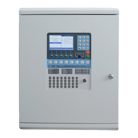
The power supply system of the FC501 control
panels complies with EN54-4.
All models are powered by the mains.
• The FC501-L has a switching power supply
which supplies up to 1.8 A at 27.6 V.
• The FC501-H has a switching power supply
which supplies up to 2.7 A at 27.6 V.
• The FC501-HK has a switching power supply
which supplies up to 2.7 A at 27.6 V.
All models can house two 12 V batteries. When
these are connected in series, they can supply 24 V
to the control panel and peripherals in the event of
a power cut.
For suitable batteries, refer to Table 33.
Note:
If necessary, the FC501-H and FC501-HK control
panel can be connected to two 12 V, 38 Ah
batteries in an external cabinet. See Mounting
the 38 Ah battery cabinet.
This control panel can detect, signal and store in
memory the following power faults:
• Shorted 24A or 24R outputs
• Low battery
• Battery fault
• Battery disconnected
• Battery trouble
• Earth fault
• Mains failure power supply fault
The battery fault may be signaled with a delay up
to 1 minute. The mains fault is signaled when the
programmed delay expires.
The control panel monitors the batteries status at all
times, through static tests and dynamic tests.
Static Test: The static test monitors the battery
charge during mains failure. In the event of low
battery voltage, below 22.8 V, the Low Battery LED
turns ON. If this occurs, you must restore the mains
power before the batteries empty, otherwise, the
system will shutdown.
Dynamic Test: The dynamic test monitors the
operating capacity of the batteries. If the batteries
do not meet the test requirements, the No Battery
LED turns ON. If this occurs, you must replace the
FC501 Addressable Fire Control Panels Installation Manual6


