Tyco DV-5 User manual

General
Description
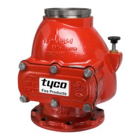
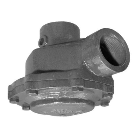
The DN40 thru DN200, Model DV-5
Deluge Valves are diaphragm type
valves used as “automatic water con-
trol valves” in deluge fire protection
systems. When properly trimmed, the
DV-5 Valves are also able to provide
actuation of fire alarms upon system
operation.
The diaphragm style design of the
DV-5 Valve allows external resetting
— providing for easy resetting of a
deluge system without having to open
a valve handhole cover to manually
reposition a clapper and/or latch
mechanism. Simply re-pressurizing
the diaphragm chamber resets the
valve.
The DV-5 also features internal and
external coating of the valve to pro-
vide corrosion resistance. The exter-
nal corrosion resistance of the Rilsan
coating permits the use of the DV-5
in corrosive atmospheres associated
with many types of industrial process-
ing plants and outdoor installations.
WARNING
The Model DV-5 Deluge Valves de-
scribed herein must be installed and
maintained in compliance with this
document, as well as with the appli-
cable standards of the Approval agen-
cy, in addition to the standards of any
other authorities having jurisdiction.
Failure to do so may impair the per-
formance of these devices.
The owner is responsible for maintain-
ing their fire protection system and de
vices in proper operating condition.
The installing contractor or manufac-
turer should be contacted with to any
questions.
End Connections Available and Weights
Outlet
Inlet DN40 DN50 DN80 DN100 DN150 DN200
Nominal Valve SizeEnd Connection
ThreadThread
GrooveGroove
Groove
Flange
FlangeFlange
N/AN/A N/AN/A
N/AN/A
N/AN/A
4,1 kg
3,6 kg
5,4 kg
4,5 kg 14,1 kg
17,7 kg
21,3 kg 36,3 kg
33,6 kg
27,7 kg 44,9 kg
48,5 kg
52,3 kg
68,1 kg
77,8 kg
87,5 kg
Model DV-5 Deluge Valve, Diaphragm Style
DN40 thru DN200, Vertical Installation, 16 Bar
VdS/LPCB European Conformity Valve Trim
Technical Services: Tel: (800) 381-9312 / Fax: (800) 791-5500
Page 1 of 28 JUNE, 2007 TFP1338

NO.
(a)
DESCRIPTION P/N
REPLACEMENT PARTS
Diaphragm Kit, Includes Item 2
92-477-1-105DN40 Valve
92-477-1-107DN50 Valve
92-477-1-109DN80 Valve
92-477-1-101DN100 Valve
DN150 Valve 92-477-1-103
DN200 Valve 92-477-1-111
DIAPHRAGM
ORIENTATION
TAB
TAB ORIENTED
PERPENDICULAR
TO VALVE BODY
DIAPHRAGM
3
6
(DN100, DN150,
& DN200 VALVES
ONLY)
5
4
STUDS,
SEE NOTE 2
2
1
4
1.
NOTES:
NR - Not Replaceable.
2. DN100, DN150, & DN200 Valve Bodies
are equipped with studs as shown,
allowing Diaphragm and Handhole
Cover to be "hung" in place to
ease assembly. Bodies of DN40, DN50,
& DN80 Valves are not equipped with
studs.
. . . . . . . . . . . . . .
. . . . . . . . . . . . . .
. . . . . . . . . . . . . .
. . . . . . . . . . . . .
. . . . . . . . . . . . .
. . . . . . . . . . . . .
Hex Bolt,
DN100 Valve,
DN150 Valve,
5
M16 x 50 CH
DN50 & DN80 Valves,
CHDN40 Valve, M12 x 30
Hex Nut,6
DN200 Valve,
DN100 & DN150 Valves,
CHDN200 Valves, M20
Handhole Cover NR
4 Flat Washer,
NO.
1
QTY.DESCRIPTION Refer to Kit
(a)
Valve Body
Diaphragm
NR
2
3
VALVE PARTS
DN40 Valve, M12 CH
CH
DN50 & DN80 Valves,
DN100 & DN150 Valves,
CHDN200 Valves, M20
M16
CHM16
M16 x 50 CH
M16 x 55 CH
M20 x 70 CH
CHM16
4
4
2
1
1
1
4
4
8
8
6
6
6
2
. . . . . . . . . . . . .
. .
. . . .
. . . . . . .
. . . . . . . . . . .
. . . . . . . . . . .
. . . . . .
. . . . . . . . . . . . . . . . .
. . . .
. . . . . . . . . . . . . . . . .
. . . . . . . . . . . . .
. . . . . . . . . . . . .
. . . . . . . . . . . . .
. . . . . . . . . . . . . . . . .
Same drilling as for BS 4504 Section 3.2 (PN16) and DIN 2532 (PN16).
Same drilling as for BS 4504 Section 3.2 (PN10) and DIN 2532 (PN10).
Dim. A
Bolt Circle
Diameter
Dim. B
Bolt Hole
Diameter
Qty. N
Number of
Bolt Holes
3
4
Flange end DN40 & DN50 DV-5 Valves are not offered.
1
Same drilling as for B16.5 (Class 150) and B16.42 (Class 250).
2
FIGURE 1
DN40 thru DN200 MODEL DV-5 DELUGE VALVE
— ASSEMBLY —
TABLE A — DIMENSIONAL SPECIFICATIONS FOR SELECTION OF FLANGE DRILLING
Nominal
Valve
Size1
Flange Drilling Specification
Nominal Dimensions in Millimeters
ANSI B16.1
(Class 125)2
ISO 7005-2
(PN10)3
ISO 7005-2
(PN16)4
JIS B 2210
(10K)
AS 2129
(Table E)
Dim.
A
Dim.
B
Qty.
N
Dim.
A
Dim.
B
Qty.
N
Dim.
A
Dim.
B
Qty.
N
Dim.
A
Dim.
B
Qty.
N
Dim.
A
Dim.
B
Qty.
N
DN80 152,4 19,0 4
USE
ISO 2084
(PN16)
160,0 19,0 8 N/A N/A
DN100 190,5 19,0 8 180,0 19,0 8 175,0 15,0 8 178,0 18,0 8
DN150 241,3 22,2 8 240,0 23,0 8 240,0 19,0 8 235,0 22,0 8
DN200 298,5 22,2 8 295,0 23,0 8 295,0 23,0 12 N/A 292,0 22,0 8
Page 2 of 28 TFP1338

Technical
Data
Approvals:
VdS and LPCB Approved when
trimmed as detailed in this Technical
Data Sheet for
European Conformity
applications.
Deluge Valve:
Components for the DN40 thru DN200,
Model DV-5 Deluge Valves are shown
in Figure 1. The DV-5 Valves are for
vertical installations. They are rated
for use at a service pressures of 1,4
to 16,0 bar, except that the DN50 has
a minimum operating pressure of 2,0
bar, and the minimum residual pres-
sure for sizes DN40 thru DN200 must
be 2,0 bar for flow velocities greater
than 8,5 m/s.
The take-out dimensions are shown in
Figure 2, and the flanged connections
are available drilled per ANSI, ISO, AS,
and JIS specifications (Ref. Table A).
The DV-5 Valves are provided with
ISO 7/1 threaded ports that will readily
accept the trim arrangements detailed
in this Technical Data Sheet.
Pressure Loss:
Refer to Graph A on Page 5.
Patents:
U.S.A. : 6,095,484
Materials Of
Construction
Body. Rilsan* coated ductile iron per
ASTM A536-77, Grade 65-45-12.
Handhole Cover. Rilsan* coated duc-
tile iron per ASTM A536-77, Grade
65-45-12.
Diaphragm. Nylon fabric reinforced,
natural rubber per ASTM D2000.
Diaphragm Cover Fasteners. Galva-
nized carbon steel.
*Rilsan is a registered trademark of
ATOFINA Chemicals, Inc. (The Rilsan
coating is a polyamide (Nylon 11)
coating.)
Operating
Principles
The Model DV-5 Deluge Valve is a
diaphragm style valve that depends
upon water pressure in the Diaphragm
Chamber (Ref. Figure 3A) to hold the
Diaphragm closed against the water
supply pressure. When the DV-5 Valve
is set for service, the Diaphragm
Chamber is pressurized through the
trim connections from the inlet side of
the system’s stop valve. Opening an
actuation device, for example the so-
lenoid valve in the Electric Actuation
Trim (Ref. Figure 6), releases water
from the Diaphragm Chamber faster
than it can be replenished through the
3,2 mm restriction within the Automat-
ic Shut-Off Valve provided in the dia-
phragm chamber supply connection.
Release of water pressure results in a
rapid pressure drop in the Diaphragm
Chamber and the force differential ap-
plied through the Diaphragm to hold
the Diaphragm in the set position is
reduced below the valve trip point.
The water supply pressure then forces
the Diaphragm open permitting water
to flow into the system piping, as well
as through the Alarm Port to actuate
the system alarms (Ref. Figure 3B).
Groove x Groove & Thread x Thread
Groove x Groove, Flange x Flange,
& Flange x Groove
Groove x Groove, Flange x Flange,
& Flange x Groove
Groove x Groove, Flange x Flange,
& Flange x Groove
460 mm
400 mm
324 mm
220 mm
204 mm
570 mm
Groove x Groove, Flange x Flange,
& Flange x Groove
DN40
DN50
DN80
DN100
DN150
DN200
FIGURE 2
MODEL DV-5 DELUGE VALVE
— TAKE-OUT DIMENSIONS —
(Applies to all available
end configurations)
TFP1338 Page 3 of 28

FIGURE 3C
FIGURE 3A
FIGURE 3D
FIGURE 3B
OPERATED POSITION
WATER SUPPLY SHUT OFF
RESIDUAL DRAIN POSITIONSYSTEM DRAIN POSITION
WATER SUPPLY SHUT OFF
DRAIN FROM SYSTEM
SET POSITION
16 BAR MAX. WATER SUPPLY
WATERFLOW
WATERFLOW FROM WATER SUPPLY
TO ALARM
WATERFLOW TO SYSTEMSYSTEM OPEN TO ATMOSPHERE
ALARM PORT
OPEN TO
ALARM PORT
ATMOSPHERE
RESIDUAL DRAIN FROM SYSTEM
& ALARM
SUPPLY
PRESSURE
DIAPHRAGM
SEAT
WATERWAY
SUPPLY
DIAPHRAGM
USED
VALVE
PORT
TEST PORT
CHAMBER
OPEN TO
DIAPHRAGM
ATMOSPHERE
CHAMBER
DIAPHRAGM
CHAMBER
VALVE
WATERWAY
WATER
FLEXES TO
ITS SEATED
AUTOMATICALLY
DIAPHRAGM
VALVE
WATERWAY
DRAIN
SYSTEM DRAIN
SYSTEM
CHAMBER
OPEN TO
DIAPHRAGM
ATMOSPHERE
WATERFLOW
TO AUTOMATIC
SHUT-OFF
VALVE
OPENING
VALVE
RETRACTS
DIAPHRAGM
WATERWAY
POSTION
PORT
NOT
1/2"
3/4"
1-1/4"
1/2"
1/2"
P1
P2
P3
P4
P5
Port DN40 DN50 DN80 DN100 DN150 DN200
1/2"
3/4"
3/4"
1/2"
1/2"
1/2"
3/4"
3/4"
1/2"
1/2"
1/2"
1"
2"
1/2"
1/2"
1/2"
1"
2"
1/2"
1/2"
1/2"
1"
2"
1/2"
1/2"
Port Sizes
Diaphragm Chamber Supply
Water Supply Pressure & Alarm Test
Alarm Actuation & System Drain
Not Used, Plugged
Diaphragm Chamber Supply Automatic Shut-Off Valve Actuation
Port Description
P2
P1
P3
P4
P3
P5
FIGURE 3
DN40 thru DN200 MODEL DV-5 DELUGE VALVE
— SET AND OPEN POSITIONS —
Page 4 of 28 TFP1338

0,08
0,03
0,04
0,06
0,05
0,07
0,10
0,09
0,20
0,30
0,40
0,50
0,60
50002000 3000 1000070001000600400200
FLOW RATE IN LITRES PER MINUTE (LPM)
DN50
DN40
DN150
DN100
DN80
DN200
15000
0,02
NOMINAL PRESSURE DROP IN BAR
GRAPH A
DN40 thru DN200 MODELDV-5 DELUGE VALVE
— NOMINAL PRESSURE LOSS VERSUS FLOW —
TFP1338 Page 5 of 28

Wet Pilot
Actuation
The Wet Pilot Actuation Trim forms a
part of the laboratory approval of the
DV-5 Valves and is necessary for their
proper operation.
The Wet Pilot Actuation Trim provides
for connection of a detection system
consisting of wet pilot line sprinklers
(heat detectors) and manual control
stations interconnected with minimum
DN15 steel pipe. The pilot line is con-
nected to the Wet Pilot Line Connec-
tion shown in Figure 4.
Installation dimensions are provided in
Figure 19 (Page 26).
Pilot sprinklers are to be minimum 80
K-factor orifice approved automatic
sprinklers. Manual Control Stations
are to be the Model MC-1 described in
Technical Data Sheet TFP1382.
The maximum height of a wet pilot line
above the DV-5 Valve must not exceed
the limitations shown in Table B (Page
9) as a function of the minimum water
supply pressure to the DV-5 Valve for
an equivalent length (pipe plus fittings)
of the pilot line up to 150 meters to the
most remote pilot sprinkler.
Provision must be made for installing
a 80 K-factor orifice, Inspector’s Test
Connection at the most hydraulically
demanding location of a wet pilot line
(usually adjacent to the highest and
most remote wet pilot sprinkler or
manual control station).
NOTES
Wet Pilot Lines must be maintained at
a minimum temperature of 4°C.
At a minimum, it is recommended that
internally galvanized pipe and cast
iron fittings be used for wet pilot lines.
Q
B
1
P
C
G
2HF
J
A
E
L
1 Diaphragm Supply Connection
3
2
Wet Pilot Line Connection
Water Motor Alarm Connection
C
N
3
K
MN
P
Q
L
M
K
F
J
H
G
E
D
Item
A
B
Waterflow Switch
Diaphragm Supply Valve
Manual Control Station
Diaphragm Supply Strainer
Automatic Shut-Off Valve
Diaphragm Gauge
System Gauge
Automatic Drain Valve
Water Supply Gauge
Alarm Control Valve
Alarm Test Valve
System Drain Valve
(Not used)
DV-5 Valve
Description
Stop Valve
FIGURE 4
WET PILOT ACTUATION
(Refer to Figure 7 thru 10 for specific Bills of Materials)
Page 6 of 28 TFP1338

Dry Pilot
Actuation
The Dry Pilot Actuation Trim forms a
part of the laboratory approval of the
DV-5 Valves and is necessary for their
proper operation.
The Dry Pilot Actuation Trim provides
for installation of a detection system
consisting of pilot sprinklers (heat de-
tectors) and manual control stations
interconnected with minimum DN15
steel pipe. The dry pilot line, which is
to be pressurized with air or nitrogen,
is connected to the “Dry Pilot Line
Connection” shown in Figure 5.
Installation dimensions are provided in
Figure 19 (Page 26).
Pilot sprinklers are to be minimum 80
K-factor orifice approved automatic
sprinklers. Manual Control Stations
are to be the Model MC-1 described in
Technical Data Sheet TFP1382.
The Dry Pilot Actuation Trim is provid-
ed with a Model DP-1 Dry Pilot Actu-
ator, which is described in Technical
Data Sheet TFP1380. The Actuator is
rated for use at a maximum pilot ser-
vice pressure of 3,4 bar and a maxi-
mum water supply service pressure of
16 bar.
Graph B (Page 9) shows the “minimum
pilot line service pressure” as a func-
tion of the water supply pressure. The
pressure in the dry pilot actuation sys-
tem must be automatically maintained
using one of the following maintenance
devices, as appropriate.
• Model AMD-1 Air Maintenance De-
vice (pressure reducing type), refer
to Technical Data Sheet TFP1221.
• Model AMD-2 Air Maintenance De-
vice (compressor control type), refer
to Technical Data Sheet TFP1231.
• Model AMD-3 Nitrogen Mainte-
nance Device (high pressure reduc-
ing type), refer to Technical Data
Sheet TFP1241.
Supervision of the pressure in the dry
pilot actuation system and an alarm
that separately indicates operation of
the detection system is provided by
a low pressure alarm switch set as
follows:
• Low pressure alarm setting at ap-
proximately 0,4 bar below the mini-
mum pilot line service pressure re-
quirement shown in Graph B (page
9).
• Fire alarm setting at approximately
1,0 bar below the minimum pilot line
service pressure requirement shown
in Graph B (Page 9).
The Dry Pilot Low Pressure Switch may
be ordered as option with the valve
trim or separately ordered.
The Pressure Relief Valve provided
in the trim is factory set to relieve at
a pressure of approximately 3,1 bar;
however, it may be field adjusted to a
lower pressure, if required.
The dry pilot line is to be provided with
low point drains to enable draining on
condensate.
NOTE
At a minimum, it is recommended that
internally galvanized pipe and cast iron
fittings be used for dry pilot lines.
2
G
C
R
B
1
P
Q
E
H
J
F
A
3
M
N
K
V
S
L
4
T
U
WATER SUPPLY PRESSURE IN BAR
RANGE OFACTUATOROPENING PRESSURE
MINIMUMSYSTEM AIRPRESSURE
S
S
E
R
P
R
I
AE
R
UR
A
B
N
I
1,0
1,0
0
2,0
3,0
4,0 7,0 10,0 13,0 16,0
DV-5 Valve
Description
Waterflow Switch
(Not used)
System Drain Valve
Automatic Drain Valve
Diaphragm Gauge
Alarm Control Valve
Water Supply Gauge
Alarm Test Valve
Diaphragm Supply Valve
Automatic Shut-Off Valve
Manual Control Station
Dry Pilot Actuator
Dry Pilot Low Pressure Switch
Dry Pilot Air Supply Valve
Diaphragm Supply Strainer
System Gauge
Stop Valve
Diaphragm Supply Connection
Water Motor Alarm Connection
Pressure Relief Valve
Dry Pilot Air Supply Connection
Dry Pilot Line Connection
Dry Pilot Line Gauge
C
T
4
1
2
3
V
U
L
P
R
S
Q
N
M
G
K
H
J
F
D
E
Item
A
B
FIGURE 5
DRY PILOT ACTUATION
(Refer to Figure 11 thru 14 for specific Bills of Materials)
TFP1338 Page 7 of 28

Electric
Actuation
The Electric Actuation Trim forms a
part of the laboratory approval of the
DV-5 Valves and is necessary for their
proper operation.
The Electric Actuation Trim is required
for electric operation of the DV-5 Valve
by a detection system consisting of
electrical devices such as heat sen-
sitive thermostats, smoke detectors,
and/or electric manual pull stations.
Installation dimensions are provided in
Figure 19 (Page 26).
The Solenoid Valve provided in the
valve trim (P/N 52-287-1-124 described
in TFP2180) is rated as follows:
• Pressure: 17,2 bar
• Voltage: 24 VDC
• Power Consumption: 22 Watts
• Current Draw: 0,83 Amps
NOTES
Approval by VdS and LPCB is
contin¬gent on the use of the Solenoid
Valve provided with the valve trim. VdS
and LPCB only approve solenoid valves
for use in non-hazardous locations.
Consult with the applicable standards
of the Approval agency regarding in-
stallation criteria pertaining to electric
actuation circuitry.
The Electric Actuation Trim is provided
with a Model ASV-1 Automatic Shut-
Off Valve; consequently, the release
circuit of the releasing panel need only
provide the standard ten minutes of
alarm condition intended to energize
the Solenoid Valve to open. After the
ten minute duration, at which point
should the Solenoid Valve become de-
energized and close (especially while
operating under battery back-up), the
Automatic Shut-Off Valve will have
already automatically closed, there-
by preventing the DV-5 Diaphragm
Chamber from becoming re-pressur-
ized, and preventing an inadvertent
closing of the DV-5 during a fire event.
Diaphragm Supply Strainer
Diaphragm Supply Connection
Water Motor Alarm Connection
Solenoid Valve
DV-5 Valve
Waterflow Switch
Stop Valve
Automatic Drain Valve
Alarm Test Valve
System Drain Valve
(Not used)
Diaphragm Gauge
System Gauge
Water Supply Gauge
Diaphragm Supply Valve
Automatic Shut-Off Valve
Manual Control Station
Alarm Control Valve
Description
B
G
2
C
F
H
J
E
N
1
P
Q
A
R
M
K
L
Q
2
1
R
H
L
P
N
M
K
J
D
F
G
E
A
C
B
Item
FIGURE 6
ELECTRIC ACTUATION
(Refer to Figure 15 thru 18 for specific Bills of Materials)
Page 8 of 28 TFP1338

NOTES
The dew point of the pilot line air pres-
sure must be maintained below the low-
est ambient temperature to which the dry
pilot actuation system will be exposed.
Accumulation of water in the pilot line
connection to the Actuator will lower the
air pressure at which the Actuator will
open and possibly prevent proper opera-
tion. Also, introduction of moisture into
the pilot lines exposed to freezing tem-
peratures can create an ice buildup that
could prevent proper operation of the Ac-
tuator.
An air dryer must be installed where the
moisture content of the air supply is not
properly controlled at less than the re-
quired value.
It is recommended that an AMD-3 Nitro-
gen Maintenance Device be utilized in
dry pilot actuation system applications
where the dew point must be maintained
below -29°C. See Technical Data Sheet
TFP1241.
If supply pressure is variable, assume minimum expected value.
DN40
Bar DN50
Maximum Pilot Height, Meters
DN100 DN150DN80
1,4 1,4 0,9 1,4 5,2 5,5
2,8 7,3 5,8 9,1 11,9 11,6
4,1 14,0 11,6 15,8 16,5 17,1
5,5 17,8 16,5 21,3 18,3 21,3
6,9 23,8 23,8 28,3 23,8 30,2
8,3 26,5 26,5 35,7 35,10 39,6
9,7 32,0 32,6 42,4 43,3 46,9
11,0 38,7 37,5 49,1 53,6 49,1
12,1 40,8 42,1 52,4 52,1 59,1
13,8 48,8 48,8 62,8 68,0 65,8
15,5 56,4 50,6 72,2 71,0 75,0
17,2 61,3 60,7 76,5 75,3 83,8
Pressure,
Supply (2)
(1)
Maximum pilot height for up to 150 meters of equivalent length
of pilot line (pipe plus fittings).
Interpolation between data points is permitted.
(1)
(2)
(3)
DN200
2,7
11,6
13,4
17,8
19,8
29,3
43,0
51,8
50,1
62,8
76,2
78,3
WATER SUPPLY PRESSURE IN BAR
RANGE OFACTUATOROPENING PRESSURE
MINIMUMSYSTEM AIRPRESSURE
S
S
E
R
P
R
I
AE
R
UR
A
B
N
I
1,0
1,0
0
2,0
3,0
4,0 7,0 10,0 13,0 16,0
GRAPH B
DN40 thru DN200 MODEL DV-5 DELUGE VALVE
DRY PILOT LINE PRESSURE REQUIREMENTS
TABLE B
DN40 thru DN200 MODEL DV-5 DELUGE VALVE
WET PILOT DESIGN CRITERIA FOR UP TO
150 METERS OF EQUIVALENT LENGTH OF PILOT LINE (PIPE PLUS FITTINGS)
TFP1338 Page 9 of 28

Installation
NOTES
Proper operation of the Model DV-5
Deluge Valves depends upon their
trim being installed in accordance with
the instructions given in this Techni-
cal Data Sheet. Failure to follow the
appropriate trim diagram may prevent
the DV-5 Valve from functioning prop-
erly, as well as void approvals and the
manufacturer’s warranties.
The DV-5 Valve must be installed in a
readily visible and accessible location.
The DV-5 Valve, associated trim, and
wet pilot lines must be maintained at a
minimum temperature of 4°C.
Heat tracing of the DV-5 Valve or its
associated trim is not permitted. Heat
tracing can result in the formation of
hardened mineral deposits that are ca-
pable of preventing proper operation.
The Model DV-5 Deluge Valve is to be
installed in accordance with the fol-
lowing criteria:
Step 1. All nipples, fittings, and de-
vices must be clean and free of scale
and burrs before installation. Use pipe
thread sealant sparingly on male pipe
threads only.
Step 2. The DV-5 Valve must be
trimmed in accordance with one of the
trim illustrations shown in Figures 7
thru 18, as applicable.
Step 3. Care must be taken to ensure
that check valves, strainers, globe
valves, etc. are installed with the flow
arrows in the proper direction.
Step 4. Suitable provision must be
made for disposal of drain water.
Drainage water must be directed such
that it will not cause accidental dam-
age to property or danger to persons.
Step 5. Connect the Diaphragm Sup-
ply Valve to the inlet side of the sys-
tem’s Stop Valve in order to facilitate
setting of the DV-5 Valve (Ref. Figure
19).
Step 6. An Inspector’s Test Connec-
tion, as described in the Wet Pilot Actu-
ation and Dry Pilot Actuation sections
(Pages 6 and 7), must be provided for
Wet or Dry Pilot Actuation systems.
Step 7. An Air Maintenance Device,
as described in the Dry Pilot Actuation
section (Page 7), must be provided for
Dry Pilot Actuation.
Step 8. A desiccant dryer, when spec-
ified for Dry Pilot Actuation, is to be in-
stalled between a drip leg and the Air
Maintenance Device.
Step 9. The Low Pressure Alarm
Switch for Dry Pilot Actuation is to be
adjusted as follows:
• Low pressure alarm setting at approx-
imately 0,4 bar below the minimum
pilot line service pressure requirement
shown in Graph B (Page 9).
• Fire alarm setting at approximately
1,0 bar below the minimum pilot line
service pressure requirement shown
in Graph B (Page 9).
Step 10. The Pressure Relief Valve pro-
vided with the Dry Pilot Actuation Trim
is factory set to relieve at a pressure of
approximately 3,1 bar, which can typi-
cally be used for a maximum dry pilot
actuation system pressure of 2,8 bar.
The Pressure Relief Valve may be re-
set; however, it must be reset to relieve
at a pressure which is in accordance
with the requirements of the authority
having jurisdiction.
To reset the Pressure Relief Valve,
first loosen the jam nut and then ad-
just the cap accordingly — clockwise
for a higher pressure setting or coun-
ter clockwise for a lower pressure set-
ting. After verifying the desired pres-
sure setting, tighten the jam nut.
Step 11. Conduit and electrical con-
nections are to be made in accor-
dance with the applicable standards of
the Approval agency.
Step 12. Before a system hydrostatic
test is performed, the DV-5 Diaphragm
Chamber is to be depressurized, the
Automatic Drain Valve is to be tem-
porarily replaced with a plug, and the
Diaphragm Cover Bolts must be uni-
formly and securely tightened using
a cross-draw sequence. After tight-
ening, double-check to make certain
that all of the Diaphragm Cover Bolts
are securely tightened.
Page 10 of 28 TFP1338

21
9
31
240 36
5
39
30
7
19
16
36
14
42
10 11
3
4
17
8
525
26 34
42
31
1
33
23
26
18
29
38
27
35
32
37 24
6
20
34
26
36
38
18
26
23
2928
27
6
33
1
34
37
22
31
15
41
14
13
19
36
36
40
11
33
1
QTY.
2
2
1
1
1
1
1
2
1
2
2
1
1
1
1
2
1
1
1
2
2
2
3
2
. . . . . . . . .
. . . . . . . . . . . . . . . . . . . . . . . . . . . . . . . .
. . . . . . . . . . . . . . . . . . . . . . . . . . . . . . . . . . . . . . . . . . . . . . .
. . . . . . . . . . . . . . . . . . . . . . . . . . . . . . . .
. . . . . . . . . . . . . . . . . . . . . . . . . . . . .
. . . . . . .
. . . . . . .
. . . . . . .
. . . . . . . . .
. . . .
. . . .
. . . . . . . . . . . . . . . . . . . . .
. . . . . . . . . . . . . . . . . . . . . . . . . . . .
. . .
. . . . . . . . . . . . . . . . . . . . . . . . . . . . . . . . . . . . . . . . . . . . . .
. . . . . . . . . . . . . . . . . . . . . . . . . . . . . . . . . . . . . . . .
. . . . . . . . . . . . . . . . . . . . . . . . . . . . . . .
. . . . . . . . . . . . . . . . . . . . . . . . . . . . . . . . . . . . . . . . . . .
. . . .
. . . . . . . . . . . . . . . . . . . . . . . . . . .
. . . . . . . . . . . . . . . . . . . . . . . . . . .
. . . . . . . . . . . . . . . . . . . . . . . . . . . .
. . . . . . . . . . . . . . . . . . . . . . . . . . . . . . . . . . . . . . . .
. . . . . . . . . . . . . . . . . . . . . . . . . . . . . . . . . . . . .
24
11
18
17
20
23
21
22
19
14
13
12
16
15
6
8
7
10
9
2
3
4
1
5
NO. DESCRIPTION
AP80E4; pipe nipple; stainless steel 316; 3/4" x 80 mm
406012; Elbow 3 mm x m5
460491005; Swing type check valve 3/4"
522892001; Break rod station
model MC-1 for manual release
BSP thr. size 3/4"; galvanized
A291E2; malleable fitting; plug male;
923431021; Automatic shut-off valve;
Model ASV-1 for DV-5 trim
59304FO; Ball valve; size 1/2"; full bore; PN40; venthole thread
Optional 997908 Supervisory switch CE/VdS/LPCB/FM or UL
81900211; Straight tube connector 12 mm x 1/2" male nr
AP60D4; pipe nipple; stainless steel 316; 1/2" x 60 mm
AP100E4; pipe nipple; stainless steel 316; 3/4" x 100 mm
AP180D4; pipe nipple; stainless steel 316; 1/2" x 180 mm
AP300D4; pipe nipple; stainless steel 316; 1/2" x 300 mm
A341D4; malleable fitting; union; BSP thr. 1/2" male/fem; S.S.
661273
Optional 03128601; Bolt M4 x 25
Optional 05566800; Bolt M8 x 10
Optional 06620086; Washer M4
025500013; Water gauge; class 1.6 0-25 bar
or UL/FM 0-300 PSI
oper: k=25 & non oper: k=5
2162156; Automatic drain valve; 1/2";
kv=29.5; ul & fpr
kv=16.3; ul & fpr
1610000210; Ball valve; brass; full bore; 1/2" BSP; PN30;
1610000270; Ball valve; brass; full bore; 3/4" BSP; PN30;
20005025; Strainer y-type; NPT 1/2"; 50 mesh; SS304 screen;
Optional 2850750251; Mounting plate for supervisory switch
Optional 280200272 pipe saddle DN20 30 x 4 mm hole 11mm
bronze body
fall valve
QTY.
3
2
2
1
2
2
1
1
2
5
1
2
1
1
3
1
4
2
. . . . . . . . . . . . . . . . . . . . . . . .
. . . . . . . . . . . . . .
. . . . . . . . . . . . .
. . . . . . . .
. . . . . . . .
. . . . . . . . . . . . . . . . . . . . . . . . . . . .
. . . . . . . . . . . . . . . . . . . . . . . . . .
. . . . . . . . . . . . .
. . . . . . . . . . . . . . . . . . . . . . .
. . . . . . . . . . . . . . . . . . . . . .
. . . . . . . . . . . . . . . . . . . . . . . . . . .
. . . . . . . . . . . . .
. . . . . . . . . . . . . . . . . . . . . .
. . . . . . . . . . . . . . . . . . . . . . .
. . . . . . . . . . . . . . . . . . . . . . . .
. . . . . . . . . . . . . . . . . . . . . . . . . . .
. . . . . . . . . . . . . . . . . . . . .
. . . . . . . . . . . . . . . . . . . . . . . . . . .
38
39
41
42
40
35
34
37
36
29
31
30
33
32
25
27
26
28
NO. DESCRIPTION
ATDDMN; Adapter fitting; brass;
thr. DN15 x DN15 male; nickel pl
thr. DN15 male x compr.15mm; nickel pl
ATEEMN; Adapter fitting; brass;
ATDMCON; Adapter fitting; brass;
ETDMDFN; Adapter elbow; brass;
ETDDMN; Adapter elbow; brass;
thr. DN15 male x DN15 male; nickel pl
Grv x Grv or Thr x Thr; 3/4" drain
Deluge valve DV-5; 1-1/2" & 2'';
thr. DN15 fem x DN15 fem; nickel pl
ETDDFN; Adapter elbow; brass;
thr. male DN20 x DN20; nickel pl
RTDMBFN; Adapter reduce; brass;
thr. DN15 male x DN8 fem.; nickel pl
Pressure switch: CE, VDS, LPCB, or FM approved
RTEMDFN; Adapter reduce; brass;
thr. DN20 male x DN15 fem.; nickel pl
thr. DN20 male x DN15 male; nickel pl
RTEDMN; Adapter reduce; brass;
TTEEEFN; Adap tee; brass;
TTEMEEFN; Adap tee; brass;
V923221002; Check valve brass;
thr. DN20 fem x DN20 fem x DN20 fem; nickel pl
thr. DN20 male x DN20 fem x DN20 fem; nickel pl
thr. DN15 male x DN15 fem x DN15 fem; nickel pl
TTDMDDFN; Adapter tee; brass;
thr. DN15 male x DN15fem.; nickel pl
3 x 6 length 1.2 m; transparent
WS00000004; Pressure relief hose;
WS00000007: Copper pipe; 10 x 12 mm; length 900 mm
WS00000096; Nickel pl copper tube; 15 x 1mm for DV-5
NPT 1/2" male/male; seat buna-n
FIGURE 7
DN40 and DN50 MODEL DV-5 DELUGE VALVE
WET PILOT ACTUATION TRIM
TFP1338 Page 11 of 28

FIGURE 8
DN80 MODEL DV-5 DELUGE VALVE
WET PILOT ACTUATION TRIM
23
39
42
11
9
221
5
7
30
19
36
40
31
34
26
17
10
3
4
24
5
8
1
33
14 31
18
38
12
27
35
32
6
25
25
36
26
37
20
28
27
6
38
29
34
37
1
33
40
26
13
22
15 31
41
36
16
42
19
24
26
14
36
36
11
29 33
1
QTY.
2
1
1
1
1
1
1
1
2
2
1
1
1
1
2
1
1
1
2
2
2
3
2
. . . . . . . . . . . . . . . . . . . . . . . . . . . . . . . .
. . . . . . . . . . . . . . . . . . . . . . . . . . . . . . . .
. . . . . . . . . . . . . . . . . . . . . . . . . . . .
. . . .
. . . . . . .
. . . . . . .
. . . . . . .
. . . . . . . . .
. . . .
. . . . . . . . . . . . . . . . . . . . .
. . . . . . . . . . . . . . . . . . . . . . . . . . . .
. . . . . . . . . . . . . . . . . . . . . . . . . . . . . . . . . . . . . . . . . . . . . . .
. . .
. . . . . . . . . . . . . . . . . . . . . . . . . . . . . . . . . . . . . . . . . . . . . .
. . . . . . . . . . . . . . . . . . . . . . . . . . . . . . .
. . . . . . . . . . . . . . . . . . . . . . . . . . . . . . . . . . . . . . . . . . .
. . . . . . . . . . . . . . . . . . . . . . . . . . . . . . . . . . . . . . . .
. . . .
. . . . . . . . . . . . . . . . . . . . . . . . . . .
. . . . . . . . . . . . . . . . . . . . . . . . . . .
. . . . . . . . . . . . . . . . . . . . . . . . . . . .
. . . . . . . . . . . . . . . . . . . . . . . . . . . . . . . . . . . . .
. . . . . . . . . . . . . . . . . . . . . . . . . . . . . . . . . . . . . . . .
11
18
17
22
20
21
23
19
14
12
13
16
15
6
7
8
10
9
4
3
2
1
5
NO. DESCRIPTION
406012; Elbow 3 mm x m5
model MC-1 for manual release
522892001; Break rod station
460491005; Swing type check valve 3/4"
661273
A291G2; malleable fitting; plug male;
BSP thr. size 1-1/4"; galvanized
Model ASV-1 for DV-5 trim
923431021; Automatic shut-off valve;
59304FO; Ball valve; size 1/2"; full bore; PN40; venthole thread
Optional 997908 Supervisory switch CE/VdS/LPCB/FM or UL
81900211; Straight tube connector 12 mm x 1/2" male nr
AP60D4; pipe nipple; stainless steel 316; 1/2" x 60 mm
AP300D4; pipe nipple; stainless steel 316; 1/2" x 300 mm
AP140D4; pipe nipple; stainless steel 316; 1/2" x 140 mm
AP100E4; pipe nipple; stainless steel 316; 3/4" x 100 mm
A341D4; malleable fitting; union; BSP thr. 1/2" male/fem; S.S.
Optional 06620086; Washer M4
Optional 05566800; Bolt M8 x 10
Optional 03128601; Bolt M4 x 25
or UL/FM 0-300 PSI
025500013; Water gauge; class 1.6 0-25 bar
bronze body
kv=16.3; ul & fpr
kv=29.5; ul & fpr
oper: k=25 & non oper: k=5
2162156; Automatic drain valve; 1/2";
fall valve
Optional 2850750251; Mounting plate for supervisory switch
Optional 280200272 pipe saddle DN20 30 x 4 mm hole 11mm
20005025; Strainer y-type; NPT 1/2"; 50 mesh; SS304 screen;
1610000270; Ball valve; brass; full bore; 3/4" BSP; PN30;
1610000210; Ball valve; brass; full bore; 1/2" BSP; PN30;
QTY.
3
2
2
1
2
2
1
2
1
5
1
2
1
1
3
2
2
4
2
. . . . . . . . . . . . . . . . . . . . . . . .
. . . . . . . . . . . . . .
. . . . . . . . . . . . .
. . . . . . . .
. . . . . . . .
. . . . . . . . . . . . . . . . . . . . . . . . . . . .
. . . . . . . . . . . . . . . . . . . . . . . . . .
. . . . . . . . . . . . .
. . . . . . . . . . . . . . . . . . . . . . .
. . . . . . . . . . . . . . . . . . . . . . .
. . . . . . . . . . . . . . . .
. . . . . . . . . . . . . . . . . . . . . . . .
. . . . . . . . . . . . . . . . . . . . . .
. . . . . . . . . . . . .
. . . . . . . . . . . . . . . . . . . . . . .
. . . . . . . . .
. . . . . . . . .
. . . . . . . . . . . . . . . . . . . . .
. . . . . . . . . . . . . . . . . . . . . . . . . . .
39
38
41
42
40
35
34
37
36
29
31
30
32
33
25
24
27
26
28
NO. DESCRIPTION
ATEEMN; Adapter fitting; brass;
thr. DN15 male x compr.15mm; nickel pl
ATDMCON; Adapter fitting; brass;
Deluge valve DV-5; 3'';
ETDDFN; Adapter elbow; brass;
thr. DN15 fem x DN15 fem; nickel pl
Flg x Flg or Flg x Grv or Grv x Grv; 1-1/4" drain
thr. DN15 male x DN15 male; nickel pl
ETDDMN; Adapter elbow; brass;
ETDMDFN; Adapter elbow; brass;
thr. male DN20 x DN20; nickel pl
AP80D4; pipe nipple; stainless steel 316; 1/2" x 80 mm
AP80E4; pipe nipple; stainless steel 316; 3/4" x 80 mm
thr. DN15 male x DN8 fem.; nickel pl
RTDMBFN; Adapter reduce; brass;
thr. DN20 male x DN15 male; nickel pl
thr. DN20 male x DN15 fem.; nickel pl
RTEMDFN; Adapter reduce; brass;
RTEDMN; Adapter reduce; brass;
V923221002; Check valve brass;
TTEMEEFN; Adap tee; brass;
TTEEEFN; Adap tee; brass;
TTDMDDFN; Adapter tee; brass;
Pressure switch: CE, VDS, LPCB, or FM approved
thr. DN20 male x DN20 fem x DN20 fem; nickel pl
thr. DN20 fem x DN20 fem x DN20 fem; nickel pl
thr. DN15 male x DN15 fem x DN15 fem; nickel pl
thr. DN15 male x DN15fem.; nickel pl
WS00000004; Pressure relief hose;
3 x 6 length 1.2 m; transparent
WS00000007: Copper pipe; 10 x 12 mm; length 900 mm
WS00000096; Nickel pl copper tube; 15 x 1mm for DV-5
NPT 1/2" male/male; seat buna-n
Page 12 of 28 TFP1338

19
5
25
42
5
25
31
6
36
41
314
11
2
30
36
40
9
36
39
7
29 16
22
21 30
4
18
8
32
1
17
10
21
33 28
42
25
23
25
23
15 30
13
32
14
36
36
19
40
28
27
26
38
34
26
6
24
38
20
24
37
12
1
32
33
37
1
11
QTY.
2
2
1
1
1
1
2
1
2
2
2
1
1
1
1
2
1
1
1
2
2
2
3
2
. . . . . . . . .
. . . . . . . . . . . . . . . . . . . . . . . . . . . . . . . . . . . . .
. . . . . . . . . . . . . . . . . . . . . . . . . . . . . . . . . . . . . . . . . . .
. . . . . . . . . . . . . . . . . . . . . . . . . . . . . . . . . . . . . . . .
. . . . . . . . . . . . . . . . . . . . . . . . . . . . . . . . . . . . . . . .
. . . . . . . . . . . . . . . . . . . . . . . . . . . . . . . . . . . . . . . . . . . . . .
. . . . . . . . . . . . . . . . . . . . . . . . . . . . . . . . . . . . . . . . . . . . . . .
. . . . . . . . . . . . . . . . . . . . . . . . . . . . . . . .
. . . . . . . . . . . . . . . . . . . . . . . . . . . . . . . .
. . . .
. . . . . . . . . . . . . . . . . . . . . . . . . . . . . . .
. . . . . . .
. . . . . . .
. . . . . . .
. . . . . . . . .
. . . .
. . .
. . . . . . . . . . . . . . . . . . . . .
. . . . . . . . . . . . . . . . . . . . . . . . . . . .
. . . . . . . . . . . . . . . . . . . . . . . . . . . . . . .
. . . .
. . . . . . . . . . . . . . . . . . . . . . . . . . .
. . . . . . . . . . . . . . . . . . . . . . . . . . .
. . . . . . . . . . . . . . . . . . . . . . . . . . . .
24
11
18
17
22
21
20
23
19
13
12
14
16
15
6
9
10
7
8
4
3
2
1
5
DESCRIPTIONNO.
AP80E4; pipe nipple; stainless steel 316; 3/4" x 80 mm
Optional 06620086; Washer M4
Optional 05566800; Bolt M8 x 10
Optional 03128601; Bolt M4 x 25
025500013; Water gauge; class 1.6 0-25 bar
oper: k=25 & non oper: k=5
1610000270; Ball valve; brass; full bore; 3/4" BSP; PN30;
2162156; Automatic drain valve; 1/2";
20005025; Strainer y-type; NPT 1/2"; 50 mesh; SS304 screen;
1610000210; Ball valve; brass; full bore; 1/2" BSP; PN30;
406012; Elbow 3 mm x m5
522892001; Break rod station
model MC-1 for manual release
59304FO; Ball valve; size 1/2"; full bore; PN40; venthole thread
Optional 2850750251; Mounting plate for supervisory switch
460491005; Swing type check valve 3/4"
BSP thr. size 2"; galvanized
A291I2; malleable fitting; plug male;
Model ASV-1 for DV-5 trim
Optional 997908 Supervisory switch CE/VdS/LPCB/FM or UL
923431021; Automatic shut-off valve;
81900211; Straight tube connector 12 mm x 1/2" male nr
Optional 280200272 pipe saddle DN20 30 x 4 mm hole 11mm
AP100E4; pipe nipple; stainless steel 316; 3/4" x 100 mm
AP120D4; pipe nipple; stainless steel 316; 1/2" x 120 mm
AP300D4; pipe nipple; stainless steel 316; 1/2" x 300 mm
AP60D4; pipe nipple; stainless steel 316; 1/2" x 60 mm
A341D4; malleable fitting; union; BSP thr. 1/2" male/fem; S.S.
661273
kv=29.5; ul & fpr
bronze body
fall valve
or UL/FM 0-300 PSI
kv=16.3; ul & fpr
QTY.
2
2
2
2
1
2
1
1
1
5
2
1
1
3
3
4
1
1
. . . . . . . . . . . . . . . . . . . . . . .
. . . . . . . . . . . . . . . . . . . . . . . . . . . . . . . . . . . . . .
. . . . . . . . . . . . . .
. . . . . . . . . . . . .
. . . . . . . .
. . . . . . . .
. . . . . . . . . . . . . . . . . . . . . . . . . . . .
. . . . . . . . . . . . . . . . . . . . . . . . . .
. . . . . . . . . . . . . . . . . . . . . . .
. . . . . . . . . . . . .
. . . . . . . . . . . . . . . . . . . . . . . .
. . . . . . . . . . . . . . . . . . . . . .
. . . . . . . . . . . . .
. . . . . . . . . . . . . . . . . . . . . . .
. . . . . . . . . . . . . . . . . . . . . . . .
. . . . . . . . . . . . . . . . . . . . .
. . . . . . . . . . . . . . . . . . . . . . . . . . .
. . . . . . . . . . . . . . . . . . .
38
39
41
42
40
35
34
37
36
29
31
30
33
32
25
27
26
28
NO. DESCRIPTION
thr. DN20 male x DN15 male; nickel pl
thr. DN20 male x DN15 fem.; nickel pl
RTFEMN; Reduce thr. fitting; nickel pl brass;
RTEMDFN; Adapter reduce; brass;
V923221002; Check valve brass;
thr. DN15 male x DN15 fem x DN15 fem; nickel pl
thr. DN20 fem x DN20 fem x DN20 fem; nickel pl
thr. DN20 male x DN20 fem x DN20 fem; nickel pl
TTDMDDFN; Adapter tee; brass;
WS00000096; Nickel pl copper tube; 15 x 1mm for DV-5
WS00000007: Copper pipe; 10 x 12 mm; length 900 mm
WS00000004; Pressure relief hose;
NPT 1/2" male/male; seat buna-n
TTEMEEFN; Adap tee; brass;
3 x 6 length 1.2 m; transparent
male DN20 x DN25
TTEEEFN; Adap tee; brass;
thr. male DN20 x DN20; nickel pl
ATEEMN; Adapter fitting; brass;
thr. DN15 male x compr.15mm; nickel pl
ATDMCON; Adapter fitting; brass;
ETDDMN; Adapter elbow; brass;
ETDDFN; Adapter elbow; brass;
thr. DN15 fem x DN15 fem; nickel pl
thr. DN15 male x DN15 male; nickel pl
Pressure switch: CE, VDS, LPCB, or FM approved
thr. DN15 male x DN15fem.; nickel pl
ETDMDFN; Adapter elbow; brass;
Flg x Flg or Flg x Grv or Grv x Grv; 2" drain
RTEDMN; Adapter reduce; brass;
thr. DN15 male x DN8 fem.; nickel pl
RTDMBFN; Adapter reduce; brass;
Deluge valve DV-5; 4'' & 6";
FIGURE 9
DN100 and DN150 MODEL DV-5 DELUGE VALVE
WET PILOT ACTUATION TRIM
TFP1338 Page 13 of 28

FIGURE 10
DN200 MODEL DV-5 DELUGE VALVE
WET PILOT ACTUATION TRIM
5
638
1
31
14
10
9
2
41
11
3
43
25
17
4
34
8
22
26
5
33
37
16
40
22
37
19
30
7
31
23
31
15
42
13
43
29
20
26
18
24
26
33
37
14
37
19
41
6
38
37
32
29
39
21 12
25
26
39
27
35
36
1
34 33
28 1
11
QTY.
1
2
2
1
1
1
1
1
1
2
2
2
1
1
1
1
2
1
1
1
2
2
2
3
2
. . . . . . . . .
. . . . . . . . .
. . . . . . . . . . . . . . . . . . . . . . . . . . . . . . . .
. . . .
. . . . . . . . . . . . . . . . . . . . . . . . . . . . . . .
. . . . . . . . . . . . . . . . . . . . . . . . . . . .
. . . . . . . . . . . . . . . . . . . . .
. . . . . . . . . . . . . . . . . . . . . . . . . . . . . . . . . . . . . . . . . . . . . . .
. . . . . . . . . . . . . . . . . . . . . . . . . . . . . . . .
. . . . . . .
. . . . . . .
. . . . . . .
. . . . . . .
. . . .
. . .
. . . .
. . . . . . . . . . . . . . . . . . . . . . . . . . . . . . . . . . . . . . . . . . . . . .
. . . . . . . . . . . . . . . . . . . . . . . . . . .
. . . . . . . . . . . . . . . . . . . . . . . . . . .
. . . . . . . . . . . . . . . . . . . . . . . . . . . .
. . . . . . . . . . . . . . . . . . . . . . . . . . . . . . . . . . . . . . . . . . .
. . . . . . . . . . . . . . . . . . . . . . . . . . . . . . .
. . . . . . . . . . . . . . . . . . . . . . . . . . . . . . . . . . . . .
. . . . . . . . . . . . . . . . . . . . . . . . . . . . . . . . . . . . . . . .
. . . . . . . . . . . . . . . . . . . . . . . . . . . . . . . . . . . . . . . .
24
25
11
18
17
22
21
20
23
19
14
12
13
16
15
6
7
8
10
9
4
3
2
1
5
NO. DESCRIPTION
AP60D4; pipe nipple; stainless steel 316; 1/2" x 60 mm
AP80E4; pipe nipple; stainless steel 316; 3/4" x 80 mm
406012; Elbow 3 mm x m5
Model ASV-1 for DV-5 trim
BSP thr. size 2"; galvanized
A291I2; malleable fitting; plug male;
Optional 997908 Supervisory switch CE/VdS/LPCB/FM or UL
AP300D4; pipe nipple; stainless steel 316; 1/2" x 300 mm
AP100E4; pipe nipple; stainless steel 316; 3/4" x 100 mm
AP100D4; pipe nipple; stainless steel 316; 1/2" x 100 mm
AP120D4; pipe nipple; stainless steel 316; 1/2" x 120 mm
A341D4; malleable fitting; union; BSP thr. 1/2" male/fem; S.S.
460491005; Swing type check valve 3/4"
model MC-1 for manual release
522892001; Break rod station
923431021; Automatic shut-off valve;
81900211; Straight tube connector 12 mm x 1/2" male nr
59304FO; Ball valve; size 1/2"; full bore; PN40; venthole thread
661273
1610000270; Ball valve; brass; full bore; 3/4" BSP; PN30;
2162156; Automatic drain valve; 1/2";
oper: k=25 & non oper: k=5
Optional 280200272 pipe saddle DN20 30 x 4 mm hole 11mm
Optional 2850750251; Mounting plate for supervisory switch
20005025; Strainer y-type; NPT 1/2"; 50 mesh; SS304 screen;
bronze body
kv=29.5; ul & fpr
fall valve
Optional 06620086; Washer M4
Optional 05566800; Bolt M8 x 10
Optional 03128601; Bolt M4 x 25
025500013; Water gauge; class 1.6 0-25 bar
or UL/FM 0-300 PSI
1610000210; Ball valve; brass; full bore; 1/2" BSP; PN30;
kv=16.3; ul & fpr
QTY.
2
2
2
1
2
2
1
1
1
5
2
1
1
3
3
4
1
1
. . . . . . . . . . . . . . . . . . . . . . .
. . . . . . . . . . . . . .
. . . . . . . . . . . . .
. . . . . . . .
. . . . . . . .
. . . . . . . . . . . . . . . . . . . . . . . . . . . .
. . . . . . . . . . . . . . . . . . . . . . . . . .
. . . . . . . . . . . . . . . . . . . . . . . . . . . . . . . . . . . . . .
. . . . . . . . . . . . .
. . . . . . . . . . . . . . . . . . . . . . .
. . . . . . . . . . . . . . . . . . . . . . . .
. . . . . . . . . . . . .
. . . . . . . . . . . . . . . . . . . . . .
. . . . . . . . . . . . . . . . . . . . . . .
. . . . . . . . . . . . . . . . . . . . . . . .
. . . . . . . . . . . . . . . . . . . . . . . . . . .
. . . . . . . . . . . . . . . . . . . . .
. . . . . . . . . . . . . . . . . . .
39
40
43
42
41
36
35
38
37
31
32
30
34
33
27
28
26
29
NO. DESCRIPTION
thr. DN20 male x DN15 male; nickel pl
thr. DN20 fem x DN20 fem x DN20 fem; nickel pl
TTEMEEFN; Adap tee; brass;
V923221002; Check valve brass;
thr. DN20 male x DN20 fem x DN20 fem; nickel pl
WS00000004; Pressure relief hose;
3 x 6 length 1.2 m; transparent
WS00000007: Copper pipe; 10 x 12 mm; length 900 mm
WS00000096; Nickel pl copper tube; 15 x 1mm for DV-5
NPT 1/2" male/male; seat buna-n
thr. DN20 male x DN15 fem.; nickel pl
RTEMDFN; Adapter reduce; brass;
RTFEMN; Reduce thr. fitting; nickel pl brass;
TTEEEFN; Adap tee; brass;
thr. DN15 male x DN15 fem x DN15 fem; nickel pl
TTDMDDFN; Adapter tee; brass;
male DN20 x DN25
thr. DN15 fem x DN15 fem; nickel pl
thr. DN15 male x DN15 male; nickel pl
thr. DN15 male x DN15fem.; nickel pl
ETDMDFN; Adapter elbow; brass;
ETDDMN; Adapter elbow; brass;
Pressure switch: CE, VDS, LPCB, or FM approved
thr. DN15 male x DN8 fem.; nickel pl
RTEDMN; Adapter reduce; brass;
RTDMBFN; Adapter reduce; brass;
thr. DN15 male x compr.15mm; nickel pl
ATEEMN; Adapter fitting; brass;
thr. male DN20 x DN20; nickel pl
ATDMCON; Adapter fitting; brass;
ETDDFN; Adapter elbow; brass;
Flg x Flg or Flg x Grv or Grv x Grv; 2" drain
Deluge valve DV-5; 8";
Page 14 of 28 TFP1338

1
8
30
24
5
7
17
36
5
12
11
2
3
4
47
13
22 31
43
46
36
35
43
26
21
40
36
18
48
16
27
43
40
19
43
17
30
37
38
18
6
25
29
43
644
49
31
29
41
31
45
32 15
49
31
23
34
28
33
28
1
44
32
45
39 42
34
14
41 40
13
36
43
43
48
47
40
43
4
10
22
20
5
28
912
1
47
47
17
40
43
13
2
3
1
1
1
1
1
2
2
1
1
1
1
3
2
1
1
1
1
2
3
4
4
3
2
1
3
QTY.
4
. . . . . . .
. . . . . . .
. . . . . . . . . . . . . . . . . . . . . . . . . . . . . . . .
. . . . . . . . . . . . . . . . . . . . . . . . . . . . .
. . . . . . . . . . . . . . . . . . . . . . . . . . . . .
. . . .
. . . .
. . . . . . . . . . . . . . . . . . . . . . . . . . . . . . .
. . . . . . . . . . . . . . . . . . . . . . . . . . . . . . . . . . . . . . . . . . . . . .
. . . . . . . . . . . . . . . . . . . . . . . . . . . . . . . . . . . . . . . . . . . . . . .
. . . . . . . . . . . . . . . . . . . . .
. . . . . . . . . . . . . . . . . . . . . . . . . . . .
. . . . . . . . . . . . . . . . . . . . . . . . . . . . .
. . . . . . . . . . . . . . . . . . . . . . . . . . . . . . . .
. . .
. . . . . . . . .
. . . . . . . . . . . . . . . . . . . . . . . . . . .
. . . . . . . . . . . . . . . . . . . . . . . . . . . . . . . .
. . . .
. . . . . . . . . . . . . . . . . . . . . . . . . . .
. . . . . . . . . . . . . . . . . . . . . . . . . . . .
. . . . . . . . . . . . . . . . . . . . . . . . . . . . . . . . . . . . . . . . . . .
. . . . . . . . . . . . . . . . . . . . . . . . . . . . . . . . . . . . . . . .
. . . . . . . . . . . . . . . . . . . . . . . . . . . . . . . . . . . . . . . .
. . . . . . . . . . . . . . . . . . . . . . . . . . . . . . . . . . . . .
. . . . . . . . . . . . . . . . . . . . . . . . . . .
20
25
26
21
23
24
22
14
17
16
15
19
18
10
11
9
13
12
3
4
5
7
6
8
1
2
923431020; Pressure relief valve;
923431021; Automatic shut-off valve;
NPT1/4"; set to relief at 45 psi
Model ASV-1 for DV-5 trim
A291E2; malleable fitting; plug male;
BSP thr. size 3/4"; galvanized
A341D4; malleable fitting; union; BSP thr. 1/2" male/fem; S.S.
AP100E4; pipe nipple; stainless steel 316; 3/4" x 100 mm
AP180D4; pipe nipple; stainless steel 316; 1/2" x 180 mm
Optional 997908 Supervisory switch CE/VdS/LPCB/FM or UL
oper: k=25 & non oper: k=5
280200212; Pipe saddle DN15; mat: electro zinc plated
Optional Low pressure switch;
CE, VdS, LPCB or FM approved
Optional 280200272 pipe saddle DN20 30 x 4 mm hole 11mm
model MC-1 for manual release
460491005; Swing type check valve 3/4"
522892001; Break rod station
406012; Elbow 3 mm x m5
522801001; Dry pilot actuator
Air pressure gauge 0-10 bar;
fm&ul approved; 0-250 psi
81900211; Straight tube connector 12 mm x 1/2" male nr
59304FO; Ball valve; size 1/2"; full bore; PN40; venthole thread
Optional 2850750251; Mounting plate for supervisory switch
661273
fall valve
DESCRIPTION
025500013; Water gauge; class 1.6 0-25 bar
or UL/FM 0-300 PSI
Optional 06620086; Washer M4
Optional 05566800; Bolt M8 x 10
kv=16.3; ul & fpr
kv=29.5; ul & fpr
2162156; Automatic drain valve; 1/2";
20005025; Strainer y-type; NPT 1/2"; 50 mesh; SS304 screen;
1610000270; Ball valve; brass; full bore; 3/4" BSP; PN30;
1610000210; Ball valve; brass; full bore; 1/2" BSP; PN30;
Optional 03128601; Bolt M4 x 25
bronze body
NO.
2
2
2
2
3
1
2
1
2
5
1
9
1
4
1
1
2
2
4
1
QTY.
1
3
2
. . . . . . . .
. . . . . . . .
. . . . . . . . . . . . .
. . . . . . . . . . . . . .
. . . . . . . . . . . . . . . . . . . . . . . . . . . .
. . . . . . . . . . . . . . . . . . . . . . . . . .
. . . . . . . . . . . . . . . . . . . . . . . .
. . . . . . . . . . . . .
. . . . . . . . . . . . .
. . . . . . . . . . . . . . . . . . . . . . .
. . . . . . . . . . . . . . . . . . . . . . . .
. . . . . . . . . . . . . . . . . . . . . .
. . . . . . . . . . . . . . . . .
. . . . . . . . . . . . . . . . . . . . . .
. . . . . . . . . . . . . . . . . . . . . . .
. . . . . . . . . . . . . . . . . . . . . .
. . . . . . . . . . . . . . . . . . . . .
. . . . . . . . . . . . . . . . . . . . . . . . . . .
. . . . . . . . . . . . . . . . . . . . . . . . . . .
. . . . . . . . . . . . . . . . . . . . . . . . . . .
. . . . . . .
. . . . . . . . .
. . . . . . . . .
44
48
49
45
47
46
39
41
40
43
42
35
36
38
37
30
33
32
31
34
27
28
29
TTEEEFN; Adap tee; brass;
TTEMEEFN; Adap tee; brass;
thr. DN20 male x DN20 fem x DN20 fem; nickel pl
thr. DN20 fem x DN20 fem x DN20 fem; nickel pl
NPT 1/2" male/male; seat buna-n
WS00000004; Pressure relief hose;
3 x 6 length 1.2 m; transparent
WS00000096; Nickel pl copper tube; 15 x 1mm for DV-5
WS00000007: Copper pipe; 10 x 12 mm; length 900 mm
V923221002; Check valve brass;
AP300D4; pipe nipple; stainless steel 316; 1/2" x 300 mm
AP60D4; pipe nipple; stainless steel 316; 1/2" x 60 mm
Deluge valve DV-5; 1-1/2" & 2'';
thr. male DN20 x DN20; nickel pl
ATEEMN; Adapter fitting; brass;
thr. DN15 x DN15 male; nickel pl
ATDDMN; Adapter fitting; brass;
thr. DN15 male x compr.15mm; nickel pl
ATDMCON; Adapter fitting; brass;
ETDDFN; Adapter elbow; brass;
Grv x Grv or Thr x Thr; 3/4" drain
thr. DN15 male x DN15 male; nickel pl
ETDDMN; Adapter elbow; brass;
thr. DN15 male x DN15fem.; nickel pl
ETDMDFN; Adapter elbow; brass;
thr. DN15 fem x DN15 fem; nickel pl
RTEDMN; Adapter reduce; brass;
thr. DN20 male x DN15 male; nickel pl
thr. DN15 male x DN8 fem.; nickel pl
RTDMBFN; Adapter reduce; brass;
thr. DN20 male x DN20 male; nickel pl
Pressure switch: CE, VDS, LPCB, or FM approved
PTDN; Plug; brass; thr. DN15 male; nickel pl
thr. DN20 male x DN15 fem.; nickel pl
TTDMDDFN; Adapter tee; brass;
thr. DN15 male x DN15 fem x DN15 fem; nickel pl
RTEMDFN; Adapter reduce; brass;
ETEEMN; Adapter elbow; brass;
AP80E4; pipe nipple; stainless steel 316; 3/4" x 80 mm
NO. DESCRIPTION
FIGURE 11
DN40 and DN50 MODEL DV-5 DELUGE VALVE
DRY PILOT ACTUATION TRIM
TFP1338 Page 15 of 28

FIGURE 12
DN80 MODEL DV-5 DELUGE VALVE
DRY PILOT ACTUATION TRIM
28
44
5
47
36
7
5
24
3
2
4
11
12
22
37
17
41
44
26
13
48
37
1
37
18
49
21
44
27
16
44
32
38
13
41
28
1
18
33
30
44
32
8
42
30
45
6
29
32
50
23
34
46
35
14
42
25
33
43
40
46
45
39
41
48
944
44
49
37
44
6
5
4
3
22
10 12
2
20
41
15
24
48
50
29
32
35
13
1
17
41
31
44
17
19
1
1
1
1
1
1
2
2
1
1
1
1
3
1
2
1
1
1
2
3
4
4
3
2
1
3
QTY.
4
. . . . . . .
. . . . . . .
. . . . . . .
. . . . . . . . . . . . . . . . . . . . . . . . . . . . . . . .
. . . . . . . . . . . . . . . . . . . . . . . . . . . . .
. . . . . . . . . . . . . . . . . . . . . . . . . . . .
. . . .
. . . .
. . . . . . . . . . . . . . . . . . . . . . . . . . . . . . .
. . . . . . . . . . . . . . . . . . . . .
. . . . . . . . . . . . . . . . . . . . . . . . . . . . . . . .
. . . . . . . . . . . . . . . . . . . . . . . . . . . . . . . . . . . . . . . . . . . . . . .
. . . . . . . . . . . . . . . . . . . . . . . . . . . . .
. . . . . . . . . . . . . . . . . . . . . . . . . . . .
. . .
. . . . . . . . . . . . . . . . . . . . . . . . . . . . . . . . . . . . . . . . . . . . . .
. . . . . . . . . . . . . . . . . . . . . . . . . . . . . . . .
. . . . . . . . . . . . . . . . . . . . . . . . . . .
. . . .
. . . . . . . . .
. . . . . . . . . . . . . . . . . . . . . . . . . . .
. . . . . . . . . . . . . . . . . . . . . . . . . . . .
. . . . . . . . . . . . . . . . . . . . . . . . . . . . . . . . . . . . . . . .
. . . . . . . . . . . . . . . . . . . . . . . . . . . . . . . . . . . . . . . .
. . . . . . . . . . . . . . . . . . . . . . . . . . . . . . . . . . . . . . . . . . .
. . . . . . . . . . . . . . . . . . . . . . . . . . . . . . . . . . . . .
. . . . . . . . . . . . . . . . . . . . . . . . . . .
20
25
26
27
21
23
24
22
14
15
16
17
19
18
10
11
9
13
12
3
4
5
7
6
8
1
2
923431020; Pressure relief valve;
Model ASV-1 for DV-5 trim
923431021; Automatic shut-off valve;
NPT1/4"; set to relief at 45 psi
BSP thr. size 1-1/4"; galvanized
A291G2; malleable fitting; plug male;
A341D4; malleable fitting; union; BSP thr. 1/2" male/fem; S.S.
AP100E4; pipe nipple; stainless steel 316; 3/4" x 100 mm
AP300D4; pipe nipple; stainless steel 316; 1/2" x 300 mm
AP140D4; pipe nipple; stainless steel 316; 1/2" x 140 mm
Optional 997908 Supervisory switch CE/VdS/LPCB/FM or UL
oper: k=25 & non oper: k=5
CE, VdS, LPCB or FM approved
Optional Low pressure switch;
fall valve
522801001; Dry pilot actuator
406012; Elbow 3 mm x m5
522892001; Break rod station
model MC-1 for manual release
460491005; Swing type check valve 3/4"
661273
Air pressure gauge 0-10 bar;
fm&ul approved; 0-250 psi
Optional 280200272 pipe saddle DN20 30 x 4 mm hole 11mm
Optional 2850750251; Mounting plate for supervisory switch
280200212; Pipe saddle DN15; mat: electro zinc plated
81900211; Straight tube connector 12 mm x 1/2" male nr
59304FO; Ball valve; size 1/2"; full bore; PN40; venthole thread
DESCRIPTION
or UL/FM 0-300 PSI
025500013; Water gauge; class 1.6 0-25 bar
Optional 06620086; Washer M4
Optional 05566800; Bolt M8 x 10
kv=16.3; ul & fpr
kv=29.5; ul & fpr
bronze body
2162156; Automatic drain valve; 1/2";
1610000210; Ball valve; brass; full bore; 1/2" BSP; PN30;
1610000270; Ball valve; brass; full bore; 3/4" BSP; PN30;
20005025; Strainer y-type; NPT 1/2"; 50 mesh; SS304 screen;
Optional 03128601; Bolt M4 x 25
NO.
2
2
2
2
3
1
2
1
5
2
1
9
1
4
1
1
2
1
4
1
QTY.
2
2
2
. . . . . . . .
. . . . . . . .
. . . . . . . . . . . . .
. . . . . . . . . . . . . .
. . . . . . . . . . . . . . . . . . . . . . . . . .
. . . . . . . . . . . . . . . . . . . . . . . . . . . .
. . . . . . . . . . . . . . . . . . . . . . . .
. . . . . . . . . . . . .
. . . . . . . . . . . . .
. . . . . . . . . . . . . . . . . . . . . . . .
. . . . . . . . . . . . . . . . . . . . . . .
. . . . . . . . . . . . . . . . . . . . . . .
. . . . . . . . . . . . . . . . . . . . . .
. . . . . . . . . . . . . . . . . . . . . . .
. . . . . . . . . . . . . . . . . . . . . .
. . . . . . . . . . . . . . . . .
. . . . . . . . . . . . . . . . . . . . .
. . . . . . . . . . . . . . . . . . . . . . . . . . .
. . . . . . . . . . . . . . . . . . . . . . . . . . .
. . . . . . . . . . . . . . . .
. . . . . . . . .
. . . . . . . . .
. . . . . . . . .
45
44
45
46
48
47
40
42
41
44
43
37
36
39
38
31
34
33
32
35
24
22
25
TTEEEFN; Adap tee; brass;
TTEMEEFN; Adap tee; brass;
thr. DN20 male x DN20 fem x DN20 fem; nickel pl
thr. DN20 fem x DN20 fem x DN20 fem; nickel pl
NPT 1/2" male/male; seat buna-n
WS00000004; Pressure relief hose;
3 x 6 length 1.2 m; transparent
WS00000096; Nickel pl copper tube; 15 x 1mm for DV-5
WS00000007: Copper pipe; 10 x 12 mm; length 900 mm
V923221002; Check valve brass;
DESCRIPTION
AP80D4; pipe nipple; stainless steel 316; 1/2" x 80 mm
AP60D4; pipe nipple; stainless steel 316; 1/2" x 60 mm
Deluge valve DV-5; 3'';
thr. male DN20 x DN20; nickel pl
ATEEMN; Adapter fitting; brass;
thr. DN15 x DN15 male; nickel pl
ATDDMN; Adapter fitting; brass;
thr. DN15 male x compr.15mm; nickel pl
ATDMCON; Adapter fitting; brass;
ETDDFN; Adapter elbow; brass;
thr. DN15 fem x DN15 fem; nickel pl
thr. DN15 male x DN15 male; nickel pl
ETDDMN; Adapter elbow; brass;
thr. DN15 male x DN15fem.; nickel pl
ETDMDFN; Adapter elbow; brass;
Flg x Flg or Flg x Grv or Grv x Grv; 1-1/4" drain
RTEDMN; Adapter reduce; brass;
thr. DN20 male x DN15 male; nickel pl
thr. DN15 male x DN8 fem.; nickel pl
RTDMBFN; Adapter reduce; brass;
thr. DN20 male x DN20 male; nickel pl
PTDN; Plug; brass; thr. DN15 male; nickel pl
thr. DN20 male x DN15 fem.; nickel pl
TTDMDDFN; Adapter tee; brass;
RTEMDFN; Adapter reduce; brass;
Pressure switch: CE, VDS, LPCB, or FM approved
thr. DN15 male x DN15 fem x DN15 fem; nickel pl
ETEEMN; Adapter elbow; brass;
AP80E4; pipe nipple; stainless steel 316; 3/4" x 80 mm
NO.
Page 16 of 28 TFP1338

28
22
49
35 47
7
5
24
4
3
2
17
13
36
48 44
11
40
12
36
21
44
27
26
31
18
44
16
36
31
6
31
50
5
44
39
40
13
40
228
18
33
29
41
8
1
23
26
29
45 37 15
31
50
28
34
41 40
45
6
32
14
43
29
42
25
36
46 34 38
44
30
44
49
48
44
9
44
17
1
40
17
44
48
24
13
143
10
1222 1920
5
1
1
2
1
1
1
2
2
1
1
1
1
3
2
1
1
1
1
2
3
4
4
3
2
1
3
QTY.
4
. . . . . . .
. . . . . . .
. . . . . . .
. . . . . . . . . . . . . . . . . . . . . . . . . . . . . . . .
. . . . . . . . . . . . . . . . . . . . . . . . . . . . .
. . . .
. . . . . . . . . . . . . . . . . . . . . . . . . . . . . . .
. . . .
. . . . . . . . . . . . . . . . . . . . . . . . . . . . . . . . . . . . .
. . . . . . . . . . . . . . . . . . . . . . . . . . . . . . . . . . . . . . . .
. . . . . . . . . . . . . . . . . . . . . . . . . . . . . . . . . . . . . . . .
. . . . . . . . . . . . . . . . . . . . . . . . . . . . . . . . . . . . . . . . . . .
. . . . . . . . . . . . . . . . . . . . . . . . . . . . . . . . . . . . . . . . . . . . . .
. . . . . . . . . . . . . . . . . . . . . . . . . . . . . . . . . . . . . . . . . . . . . . .
. . . . . . . . . . . . . . . . . . . . . . . . . . . . . . .
. . . . . . . . . . . . . . . . . . . . .
. . .
. . . . . . . . . . . . . . . . . . . . . . . . . . . .
. . . . . . . . . . . . . . . . . . . . . . . . . . . . .
. . . . . . . . . . . . . . . . . . . . . . . . . . . . . . . .
. . . . . . . . .
. . . .
. . . . . . . . . . . . . . . . . . . . . . . . . . .
. . . . . . . . . . . . . . . . . . . . . . . . . . . . . . . .
. . . . . . . . . . . . . . . . . . . . . . . . . . .
. . . . . . . . . . . . . . . . . . . . . . . . . . . .
. . . . . . . . . . . . . . . . . . . . . . . . . . .
20
25
27
26
23
22
24
21
14
16
15
18
19
17
11
10
12
13
9
3
4
5
8
7
6
1
2
923431020; Pressure relief valve;
Model ASV-1 for DV-5 trim
NPT1/4"; set to relief at 45 psi
923431021; Automatic shut-off valve;
BSP thr. size 2"; galvanized
A291I2; malleable fitting; plug male;
A341D4; malleable fitting; union; BSP thr. 1/2" male/fem; S.S.
AP100E4; pipe nipple; stainless steel 316; 3/4" x 100 mm
AP300D4; pipe nipple; stainless steel 316; 1/2" x 300 mm
AP120D4; pipe nipple; stainless steel 316; 1/2" x 120 mm
Optional 997908 Supervisory switch CE/VdS/LPCB/FM or UL
025500013; Water gauge; class 1.6 0-25 bar
Optional 06620086; Washer M4
Optional 05566800; Bolt M8 x 10
20005025; Strainer y-type; NPT 1/2"; 50 mesh; SS304 screen;
1610000270; Ball valve; brass; full bore; 3/4" BSP; PN30;
1610000210; Ball valve; brass; full bore; 1/2" BSP; PN30;
Optional Low pressure switch;
CE, VdS, LPCB or FM approved
oper: k=25 & non oper: k=5
280200212; Pipe saddle DN15; mat: electro zinc plated
Optional 280200272 pipe saddle DN20 30 x 4 mm hole 11mm
2162156; Automatic drain valve; 1/2";
522892001; Break rod station
406012; Elbow 3 mm x m5
522801001; Dry pilot actuator
model MC-1 for manual release
460491005; Swing type check valve 3/4"
59304FO; Ball valve; size 1/2"; full bore; PN40; venthole thread
fm&ul approved; 0-250 psi
Air pressure gauge 0-10 bar;
81900211; Straight tube connector 12 mm x 1/2" male nr
Optional 2850750251; Mounting plate for supervisory switch
Optional 03128601; Bolt M4 x 25
661273
fall valve
kv=16.3; ul & fpr
kv=29.5; ul & fpr
bronze body
DESCRIPTION
or UL/FM 0-300 PSI
NO.
9
3
2
2
2
1
2
2
5
1
1
4
1
1
1
1
1
1
4
1
2
QTY.
2
3
. . . . . . . . . . . . .
. . . . . . . . . . . . . . . . . . . . . . . . . . . .
. . . . . . . .
. . . . . . . .
. . . . . . . . . . . . . .
. . . . . . . . . . . . . . . . . . . . . . . . . .
. . . . . . . . . . . . .
. . . . . . . . . . . . . . . . . . . . . . . . . . . . . . . . . . . . . .
. . . . . . . . . . . . . . . . . . . . . . .
. . . . . . . . . . . . . . . . . . . . . . . .
. . . . . . . . . . . . . . . . . . . . . . .
. . . . . . . . . . . . . . . . . . . . . . .
. . . . . . . . . . . . . . . . . . . . . .
. . . . . . . . . . . . .
. . . . . . . . . . . . . . . . .
. . . . . . . . . . . . . . . . . . . . . .
. . . . . . . . . . . . . . . . . . . . . . . . . . .
. . . . . . . . . . . . . . . . . . .
. . . . . . . . . . . . . . . . . . . . .
. . . . . . . . . . . . . . . . . . . . . . . . . . .
. . . . . . . . . . . . . . . . . . . . . . . .
. . . . . . . . .
. . . . . . . . .
49
50
45
46
48
47
35
40
42
41
44
43
37
36
39
38
32
33
31
34
29
28
30
thr. DN15 male x DN15 fem x DN15 fem; nickel pl
thr. DN20 fem x DN20 fem x DN20 fem; nickel pl
V923221002; Check valve brass;
NPT 1/2" male/male; seat buna-n
WS00000004; Pressure relief hose;
WS00000096; Nickel pl copper tube; 15 x 1mm for DV-5
WS00000007: Copper pipe; 10 x 12 mm; length 900 mm
thr. DN20 male x DN20 fem x DN20 fem; nickel pl
3 x 6 length 1.2 m; transparent
TTEEEFN; Adap tee; brass;
TTEMEEFN; Adap tee; brass;
ETDDMN; Adapter elbow; brass;
ETEEMN; Adapter elbow; brass;
thr. DN15 male x DN15fem.; nickel pl
thr. DN15 male x DN15 male; nickel pl
ETDMDFN; Adapter elbow; brass;
RTEDMN; Adapter reduce; brass;
Pressure switch: CE, VDS, LPCB, or FM approved
thr. DN15 male x DN8 fem.; nickel pl
thr. DN20 male x DN15 male; nickel pl
RTEMDFN; Adapter reduce; brass;
RTDMBFN; Adapter reduce; brass;
PTDN; Plug; brass; thr. DN15 male; nickel pl
TTDMDDFN; Adapter tee; brass;
RTFEMN; Reduce thr. fitting; nickel pl brass;
thr. DN20 male x DN15 fem.; nickel pl
thr. DN20 male x DN20 male; nickel pl
male DN20 x DN25
AP80E4; pipe nipple; stainless steel 316; 3/4" x 80 mm
AP60D4; pipe nipple; stainless steel 316; 1/2" x 60 mm
thr. DN15 x DN15 male; nickel pl
ATEEMN; Adapter fitting; brass;
thr. male DN20 x DN20; nickel pl
Flg x Flg or Flg x Grv or Grv x Grv; 2" drain
thr. DN15 male x compr.15mm; nickel pl
ATDMCON; Adapter fitting; brass;
ETDDFN; Adapter elbow; brass;
thr. DN15 fem x DN15 fem; nickel pl
ATDDMN; Adapter fitting; brass;
Deluge valve DV-5; 4" & 6";
NO. DESCRIPTION
FIGURE 13
DN100 and DN150 MODEL DV-5 DELUGE VALVE
DRY PILOT ACTUATION TRIM
TFP1338 Page 17 of 28

FIGURE 14
DN200 MODEL DV-5 DELUGE VALVE
DRY PILOT ACTUATION TRIM
29
22 1
37
17
2
3
11
12
13
49
4
48
24
5
7
21
45
27
36
41
45
37
32
18
16
37
50
28
45
3
4
6
32
51
47
42
8
27
5
32
6
30
46
45
40
2
42 41
14
33
26
30
43
35
47
46
44 1
50
34
51
18
25
32
23
35
38 13
45
17
41
49
24
15
13
41
29
39
45
37
45 949
45
41
31
17
45
1222
120
5
10 19
1
2
1
2
1
1
2
1
1
1
1
1
1
3
2
1
1
1
2
3
QTY.
4
4
3
2
1
3
4
. . . . . . . . . . . . . . . . . . . . . . . . . . . . . . . .
. . . .
. . . .
. . . . . . . . . . . . . . . . . . . . . . . . . . . . . . .
. . . . . . . . . . . . . . . . . . . . . . . . . . . . . . . .
. . . . . . . . . . . . . . . . . . . . . . . . . . . . .
. . . . . . .
. . . . . . .
. . . . . . .
. . . . . . . . . . . . . . . . . . . . . . . . . . . . . . .
. . . .
. . . . . . . . .
. . . . . . . . . . . . . . . . . . . . . . . . . . . . . . . . . . . . . . . . . . . . . .
. . . . . . . . . . . . . . . . . . . . . . . . . . . . . . . . . . . . . . . . . . . . . . .
. . . . . . . . . . . . . . . . . . . . . . . . . . . . . . . .
. . . . . . . . . . . . . . . . . . . . . . . . . . . . . .
. . . . . . . . . . . . . . . . . . . . . . . . . . .
. . . . . . . . . . . . . . . . . . . . . . . . . . . .
. . . . . . . . . . . . . . . . . . . . .
. . .
. . . . . . . . . . . . . . . . . . . . . . . . . . . . . . . . . . . . .
. . . . . . . . . . . . . . . . . . . . . . . . . . .
. . . . . . . . . . . . . . . . . . . . . . . . . . . .
. . . . . . . . . . . . . . . . . . . . . . . . . . . . . . . . . . . . . . . .
. . . . . . . . . . . . . . . . . . . . . . . . . . . . . . . . . . . . . . . .
. . . . . . . . . . . . . . . . . . . . . . . . . . . . . . . . . . . . . . . . . . .
. . . . . . . . . . . . . . . . . . . . . . . . . . .
24
25
26
27
20
21
22
23
14
15
16
17
18
19
10
11
9
13
12
3
4
5
7
6
8
1
2
fm&ul approved; 0-250 psi
A341D4; malleable fitting; union; BSP thr. 1/2" male/fem; S.S.
AP100D4; pipe nipple; stainless steel 316; 1/2" x 100 mm
AP120D4; pipe nipple; stainless steel 316; 1/2" x 120 mm
AP100E4; pipe nipple; stainless steel 316; 3/4" x 100 mm
923431020; Pressure relief valve;
923431021; Automatic shut-off valve;
NPT1/4"; set to relief at 45 psi
A291I2; malleable fitting; plug male;
BSP thr. size 2"; galvanized
Model ASV-1 for DV-5 trim
Optional 997908 Supervisory switch CE/VdS/LPCB/FM or UL
oper: k=25 & non oper: k=5
460491005; Swing type check valve 3/4"
model MC-1 for manual release
522801001; Dry pilot actuator
522892001; Break rod station
Air pressure gauge 0-10 bar;
81900211; Straight tube connector 12 mm x 1/2" male nr
59304FO; Ball valve; size 1/2"; full bore; PN40; venthole thread
661273
280200212; Pipe saddle DN15; mat: electro zinc plated
CE, VdS, LPCB or FM approved
Optional Low pressure switch;
406012; Elbow 3 mm x m5
Optional 280200272 pipe saddle DN20 30 x 4 mm hole 11mm
Optional 2850750251; Mounting plate for supervisory switch
fall valve
Optional 05566800; Bolt M8 x 10
Optional 06620086; Washer M4
1610000210; Ball valve; brass; full bore; 1/2" BSP; PN30;
1610000270; Ball valve; brass; full bore; 3/4" BSP; PN30;
2162156; Automatic drain valve; 1/2";
20005025; Strainer y-type; NPT 1/2"; 50 mesh; SS304 screen;
kv=29.5; ul & fpr
kv=16.3; ul & fpr
bronze body
025500013; Water gauge; class 1.6 0-25 bar
or UL/FM 0-300 PSI
Optional 03128601; Bolt M4 x 25
NO. DESCRIPTION
3
2
2
2
9
1
2
2
1
5
2
1
1
1
4
1
1
1
1
4
1
QTY.
2
1
2
. . . . . . . . . . . . . . . . . . . . . . . . . . . .
. . . . . . . .
. . . . . . . .
. . . . . . . . . . . . . .
. . . . . . . . . . . . .
. . . . . . . . . . . . .
. . . . . . . . . . . . . . . . . . . . . . . . . . .
. . . . . . . . . . . . . . . . . . . . . . . .
. . . . . . . . . . . . .
. . . . . . . . . . . . . . . . . . . . . . . . . . . . . . . . . . . . . .
. . . . . . . . . . . . . . . . . . . . . . . .
. . . . . . . . . . . . . . . . . . . . . . .
. . . . . . . . . . . . . . . . . . . . . . .
. . . . . . . . . . . . . . . . . . . . . .
. . . . . . . . . . . . . . . . . . . . . . .
. . . . . . . . . . . . . . . . .
. . . . . . . . . . . . . . . . . . . . . .
. . . . . . . . . . . . . . . . . . . . .
. . . . . . . . . . . . . . . . . . .
. . . . . . . . . . . . . . . . . . . . . . . . . . .
. . . . . . . . . . . . . . . . . . . . . . . . . . .
. . . . . . . . .
. . . . . . .
. . . . . . . . .
45
49
50
51
46
48
47
40
42
41
44
43
37
36
39
38
31
34
33
32
35
29
28
30
TTDMDDFN; Adapter tee; brass;
WS00000004; Pressure relief hose;
3 x 6 length 1.2 m; transparent
WS00000007: Copper pipe; 10 x 12 mm; length 900 mm
WS00000096; Nickel pl copper tube; 15 x 1mm for DV-5
TTEEEFN; Adap tee; brass;
thr. DN20 fem x DN20 fem x DN20 fem; nickel pl
thr. DN15 male x DN15 fem x DN15 fem; nickel pl
NPT 1/2" male/male; seat buna-n
V923221002; Check valve brass;
thr. DN20 male x DN20 fem x DN20 fem; nickel pl
TTEMEEFN; Adap tee; brass;
thr. DN15 fem x DN15 fem; nickel pl
Pressure switch: CE, VDS, LPCB, or FM approved
thr. DN15 male x DN8 fem.; nickel pl
RTEDMN; Adapter reduce; brass;
thr. DN20 male x DN15 male; nickel pl
RTDMBFN; Adapter reduce; brass;
thr. DN20 male x DN15 fem.; nickel pl
RTFEMN; Reduce thr. fitting; nickel pl brass;
RTEMDFN; Adapter reduce; brass;
male DN20 x DN25
ETDDMN; Adapter elbow; brass;
ETDMDFN; Adapter elbow; brass;
thr. DN15 male x DN15 male; nickel pl
thr. DN15 male x DN15fem.; nickel pl
thr. DN20 male x DN20 male; nickel pl
PTDN; Plug; brass; thr. DN15 male; nickel pl
ETEEMN; Adapter elbow; brass;
ATDDMN; Adapter fitting; brass;
thr. male DN20 x DN20; nickel pl
ATEEMN; Adapter fitting; brass;
thr. DN15 x DN15 male; nickel pl
ATDMCON; Adapter fitting; brass;
thr. DN15 male x compr.15mm; nickel pl
ETDDFN; Adapter elbow; brass;
Flg x Flg or Flg x Grv or Grv x Grv; 2" drain
Deluge valve DV-5; 8";
AP60D4; pipe nipple; stainless steel 316; 1/2" x 60 mm
AP300D4; pipe nipple; stainless steel 316; 1/2" x 300 mm
AP80E4; pipe nipple; stainless steel 316; 3/4" x 80 mm
NO. DESCRIPTION
Page 18 of 28 TFP1338

32
33 17
21
41
7
5
33
16
43
19
13
16
34 29
37
20
28 36
15
4
10 11
18
8
527
9
242
3
33
25
1
35
28
38
38
23
639
26
22
28
38
44
26
40
12
3130
6
29
44
25 28
35
39
1
36
31
40 43
21 38
38
24 14
35
42
11
1
15
1
1
1
2
1
1
1
2
1
1
1
2
1
1
1
2
1
1
2
2
2
2
2
QTY.
3
. . . . . . .
. . . . . . .
. . . . . . .
. . . . . . . . . . . . . . . . . . . . . . . . . . . . .
. . . . . . . . . . . . . . . . . . . . . . . . . . . . . . . .
. . . .
. . . . . . . . . . . . . . . . . . . . . . . . . . . . . . . . . . . . . . . . . . .
. . . . . . . . . . . . . . . . . . . . . . . . . . . . . . . . . . . . . . . . . . . . . .
. . . . . . . . . . . . . . . . . . . . . . . . . . . . . . . . . . . . . . . . . . . . . . .
. . . . . . . . . . . . . . . . . . . . . . . . . . . . . . . .
. . . . . . . . . . . . . . . . . . . . . . . . . . . .
. . .
. . . .
. . . . . . . . . . . . . . . . . . . . . . . . . . . . . . . .
. . . . . . . . . . . . . . . . . . . . .
. . . . . . . . . . . . . . . . . . . . .
. . . . . . . . . . . . . . . . . . . . . . . . . . . . . . .
. . . .
. . . . . . . . . . . . . . . . . . . . . . . . . . .
. . . . . . . . . . . . . . . . . . . . . . . . . . .
. . . . . . . . . . . . . . . . . . . . . . . . . . . .
. . . . . . . . . . . . . . . . . . . . . . . . . . . . . . . . . . . . . . . .
. . . . . . . . . . . . . . . . . . . . . . . . . . . . . . . . . . . . . . . .
. . . . . . . . . . . . . . . . . . . . . . . . . . . . . . . . . . . . .
19
20
23
22
24
21
14
18
16
17
15
8
9
10
12
11
13
2
3
5
7
6
4
1
A280D2; malleable fitting; nipple male;
A291E2; malleable fitting; plug male;
BSP thr. size 3/4"; galvanized
BSP size 1/2"; galvanized
AP100E4; pipe nipple; stainless steel 316; 3/4" x 100 mm
AP180D4; pipe nipple; stainless steel 316; 1/2" x 180 mm
AP300D4; pipe nipple; stainless steel 316; 1/2" x 300 mm
A341D4; malleable fitting; union; BSP thr. 1/2" male/fem; S.S.
bronze body
2162156; Automatic drain valve; 1/2";
460491005; Swing type check valve 3/4"
406012; Elbow 3 mm x m5
Solenoid valve; 1/2" 12,1 bar or 17.2 bar
model MC-1 for manual release
923431021; Automatic shut-off valve;
Model ASV-1 for DV-5 trim
522892001; Break rod station
59304FO; Ball valve; size 1/2"; full bore; PN40; venthole thread
Optional 280200272 pipe saddle DN20 30 x 4 mm hole 11mm
Optional 2850750251; Mounting plate for supervisory switch
Optional 997908 Supervisory switch CE/VdS/LPCB/FM or UL
81900211; Straight tube connector 12 mm x 1/2" male nr
oper: k=25 & non oper: k=5
661273
fall valve
DESCRIPTION
Optional 05566800; Bolt M8 x 10
Optional 03128601; Bolt M4 x 25
025500013; Water gauge; class 1.6 0-25 bar
or UL/FM 0-300 PSI
kv=16.3; ul & fpr
kv=29.5; ul & fpr
Optional 06620086; Washer M4
20005025; Strainer y-type; NPT 1/2"; 50 mesh; SS304 screen;
1610000270; Ball valve; brass; full bore; 3/4" BSP; PN30;
1610000210; Ball valve; brass; full bore; 1/2" BSP; PN30;
NO.
2
2
1
2
2
2
1
5
2
2
1
3
1
3
1
1
2
4
2
2
QTY.
. . . . . . . .
. . . . . . . .
. . . . . . . . . . . . .
. . . . . . . . . . . . . . . . . . . . . . . . . . . .
. . . . . . . . . . . . . . . . . . . . . . . . . .
. . . . . . . . . . . . .
. . . . . . . . . . . . . . . . . . . . . . .
. . . . . . . . . . . . . . . . . . . . . .
. . . . . . . . . . . . . .
. . . . . . . . . . . . . . . . . . . . . . . .
. . . . . . . . . . . . .
. . . . . . . . . . . . . . . . . . . . . .
. . . . . . . . . . . . . . . . . . . . . . .
. . . . . . . . . . . . . . . . . . . . . . . .
. . . . . . . . . . . . . . . . . . . . .
. . . . . . . . . . . . . . . . . . . . . . . . . . .
. . . . . . . . . . . . . . . . . . . . . . . . . . .
. . . . . . . . . . . . . . . . . . . . . . . . . . .
. . . . . . . . .
. . . . . . . . .
40
43
44
42
41
31
36
37
38
39
34
33
35
32
27
30
29
28
26
25
TTEMEEFN; Adap tee; brass;
NPT 1/2" male/male; seat buna-n
V923221002; Check valve brass;
WS00000004; Pressure relief hose;
3 x 6 length 1.2 m; transparent
thr. DN20 male x DN20 fem x DN20 fem; nickel pl
WS00000007: Copper pipe; 10 x 12 mm; length 900 mm
WS00000096; Nickel pl copper tube; 15 x 1mm for DV-5
thr. DN15 x DN15 male; nickel pl
ATDDMN; Adapter fitting; brass;
Deluge valve DV-5; 1-1/2" & 2'';
Grv x Grv or Thr x Thr; 3/4" drain
thr. male DN20 x DN20; nickel pl
ATEEMN; Adapter fitting; brass;
thr. DN15 male x compr.15mm; nickel pl
thr. DN15 fem x DN15 fem; nickel pl
ETDDFN; Adapter elbow; brass;
ATDMCON; Adapter fitting; brass;
AP80E4; pipe nipple; stainless steel 316; 3/4" x 80 mm
AP60D4; pipe nipple; stainless steel 316; 1/2" x 60 mm
thr. DN15 male x DN15 male; nickel pl
thr. DN15 male x DN15fem.; nickel pl
ETDMDFN; Adapter elbow; brass;
thr. DN15 male x DN8 fem.; nickel pl
RTDMBFN; Adapter reduce; brass;
Pressure switch: CE, VDS, LPCB, or FM approved
thr. DN20 male x DN15 male; nickel pl
thr. DN20 male x DN15 fem.; nickel pl
RTEMDFN; Adapter reduce; brass;
TTDMDDFN; Adapter tee; brass;
thr. DN15 male x DN15 fem x DN15 fem; nickel pl
thr. DN20 fem x DN20 fem x DN20 fem; nickel pl
TTEEEFN; Adap tee; brass;
RTEDMN; Adapter reduce; brass;
ETDDMN; Adapter elbow; brass;
NO. DESCRIPTION
FIGURE 15
DN40 and DN50 MODEL DV-5 DELUGE VALVE
ELECTRIC ACTUATION TRIM
TFP1338 Page 19 of 28

FIGURE 16
DN80 MODEL DV-5 DELUGE VALVE
ELECTRIC ACTUATION TRIM
24
23
2
41
32
33
38
42
5
21 7
16
43 33
17
38
43
25
29
37
34
36
28
18
4
8
526
9
3
10
20
1
15
11 33
35
12
6
27
28
38
39
22
44
27
30
29
40
6
1
36
39
40
35
31
44 15
21
28
26
38
38
14
11
19
13
16
42
28
31 35
1
1
1
1
2
1
1
1
2
1
1
2
1
1
1
1
2
1
1
2
2
2
2
2
QTY.
3
. . . . . . . . . . . . . . . . . . . . . . . . . . . .
. . . . . . . . . . . . . . . . . . . . . . . . . . . . . . . .
. . . . . . .
. . . . . . .
. . . . . . .
. . . .
. . . . . . . . . . . . . . . . . . . . . . . . . . . . . . . . . . . . . . . . . . .
. . . . . . . . . . . . . . . . . . . . . . . . . . . . . . . .
. . . . . . . . . . . . . . . . . . . . . . . . . . . . . . . . . . . . . . . . . . . . . . .
. . . . . . . . . . . . . . . . . . . . . . . . . . . .
. . .
. . . .
. . . . . . . . . . . . . . . . . . . . . . . . . . . . . . . . . . . . . . . . . . . . . .
. . . . . . . . . . . . . . . . . . . . .
. . . . . . . . . . . . . . . . . . . . .
. . . . . . . . . . . . . . . . . . . . . . . . . . . . . . . .
. . . . . . . . . . . . . . . . . . . . . . . . . . . . . . .
. . . .
. . . . . . . . . . . . . . . . . . . . . . . . . . .
. . . . . . . . . . . . . . . . . . . . . . . . . . .
. . . . . . . . . . . . . . . . . . . . . . . . . . . .
. . . . . . . . . . . . . . . . . . . . . . . . . . . . . . . . . . . . . . . .
. . . . . . . . . . . . . . . . . . . . . . . . . . . . . . . . . . . . . . . .
. . . . . . . . . . . . . . . . . . . . . . . . . . . . . . . . . . . . .
19
20
21
22
24
23
14
18
17
16
15
8
10
9
13
11
12
2
3
6
5
7
4
1
A280D2; malleable fitting; nipple male;
BSP thr. size 1-1/4"; galvanized
A291G2; malleable fitting; plug male;
BSP size 1/2"; galvanized
A341D4; malleable fitting; union; BSP thr. 1/2" male/fem; S.S.
AP140D4; pipe nipple; stainless steel 316; 1/2" x 140 mm
AP300D4; pipe nipple; stainless steel 316; 1/2" x 300 mm
AP100E4; pipe nipple; stainless steel 316; 3/4" x 100 mm
bronze body
2162156; Automatic drain valve; 1/2";
fall valve
406012; Elbow 3 mm x m5
Solenoid valve; 1/2" 12,1 bar or 17.2 bar
460491005; Swing type check valve 3/4"
661273
Model ASV-1 for DV-5 trim
model MC-1 for manual release
923431021; Automatic shut-off valve;
522892001; Break rod station
59304FO; Ball valve; size 1/2"; full bore; PN40; venthole thread
Optional 2850750251; Mounting plate for supervisory switch
Optional 280200272 pipe saddle DN20 30 x 4 mm hole 11mm
Optional 997908 Supervisory switch CE/VdS/LPCB/FM or UL
81900211; Straight tube connector 12 mm x 1/2" male nr
oper: k=25 & non oper: k=5
Optional 05566800; Bolt M8 x 10
Optional 03128601; Bolt M4 x 25
DESCRIPTION
or UL/FM 0-300 PSI
025500013; Water gauge; class 1.6 0-25 bar
kv=29.5; ul & fpr
kv=16.3; ul & fpr
Optional 06620086; Washer M4
1610000210; Ball valve; brass; full bore; 1/2" BSP; PN30;
1610000270; Ball valve; brass; full bore; 3/4" BSP; PN30;
20005025; Strainer y-type; NPT 1/2"; 50 mesh; SS304 screen;
NO.
2
2
2
1
2
2
2
1
5
2
3
1
3
1
2
2
1
4
1
2
QTY.
. . . . . . . . . . . . .
. . . . . . . .
. . . . . . . .
. . . . . . . . . . . . . . . . . . . . . . . . . . . .
. . . . . . . . . . . . . . . . . . . . . . . . . .
. . . . . . . . . . . . . . . . . . . . . . . .
. . . . . . . . . . . . . . . . . . . . . . .
. . . . . . . . . . . . .
. . . . . . . . . . . . . . . . . . . . . . .
. . . . . . . . . . . . . .
. . . . . . . . . . . . .
. . . . . . . . . . . . . . . . . . . . . . . .
. . . . . . . . . . . . . . . . . . . . . . .
. . . . . . . . . . . . . . . . . . . . . .
. . . . . . . . .
. . . . . . . . . . . . . . . . . . . . . . . . . . .
. . . . . . . . . . . . . . . . . . . . .
. . . . . . . . . . . . . . . .
. . . . . . . . .
. . . . . . . . .
43
44
41
42
37
39
40
38
32
33
35
34
36
27
28
29
31
30
25
26
thr. DN20 male x DN20 fem x DN20 fem; nickel pl
3 x 6 length 1.2 m; transparent
WS00000004; Pressure relief hose;
V923221002; Check valve brass;
NPT 1/2" male/male; seat buna-n
WS00000007: Copper pipe; 10 x 12 mm; length 900 mm
WS00000096; Nickel pl copper tube; 15 x 1mm for DV-5
DESCRIPTION
ATDMCON; Adapter fitting; brass;
ATEEMN; Adapter fitting; brass;
thr. male DN20 x DN20; nickel pl
ETDDMN; Adapter elbow; brass;
thr. DN15 fem x DN15 fem; nickel pl
ETDDFN; Adapter elbow; brass;
Flg x Flg or Flg x Grv or Grv x Grv; 1-1/4" drain
Deluge valve DV-5; 3'';
thr. DN15 male x compr.15mm; nickel pl
AP80E4; pipe nipple; stainless steel 316; 3/4" x 80 mm
AP80D4; pipe nipple; stainless steel 316; 1/2" x 80 mm
AP60D4; pipe nipple; stainless steel 316; 1/2" x 60 mm
RTDMBFN; Adapter reduce; brass;
thr. DN15 male x DN8 fem.; nickel pl
ETDMDFN; Adapter elbow; brass;
thr. DN15 male x DN15fem.; nickel pl
RTEDMN; Adapter reduce; brass;
RTEMDFN; Adapter reduce; brass;
thr. DN20 male x DN15 fem.; nickel pl
TTEEEFN; Adap tee; brass;
TTEMEEFN; Adap tee; brass;
TTDMDDFN; Adapter tee; brass;
thr. DN20 male x DN15 male; nickel pl
Pressure switch: CE, VDS, LPCB, or FM approved
thr. DN20 fem x DN20 fem x DN20 fem; nickel pl
thr. DN15 male x DN15 fem x DN15 fem; nickel pl
thr. DN15 male x DN15 male; nickel pl
NO.
Page 20 of 28 TFP1338
Other manuals for DV-5
7
Table of contents
Other Tyco Control Unit manuals
Popular Control Unit manuals by other brands

Nibe
Nibe MODBUS 40 Installer manual

Neles
Neles Jamesbury Series Installation maintenance and operating instructions

Bticino
Bticino Sfera 352500 User and installation manual

National Instruments
National Instruments NI 9882 Getting started guide

BERGER
BERGER WDP3-01X Safety instructions

Pfeiffer Vacuum
Pfeiffer Vacuum EVB 063 PA instruction sheet