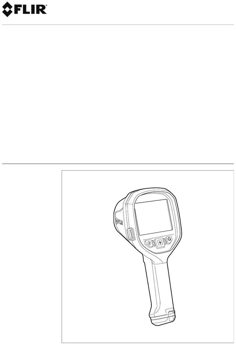
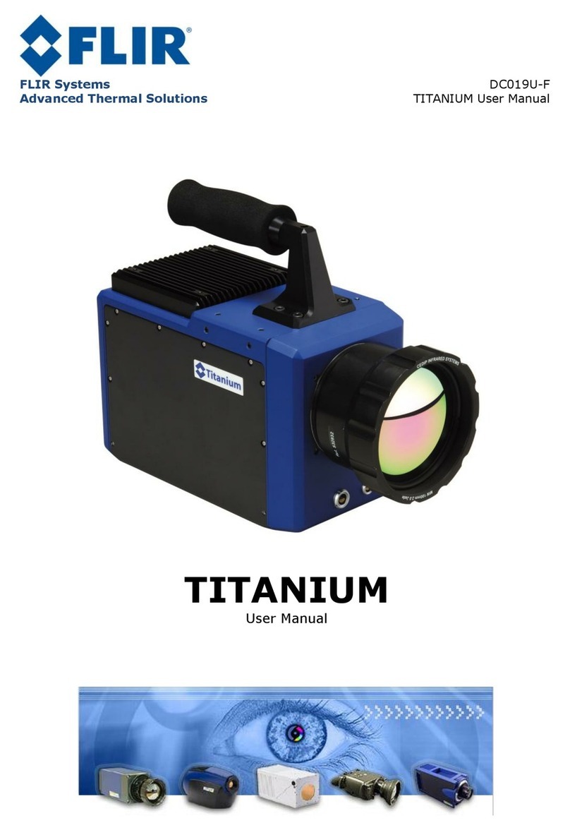
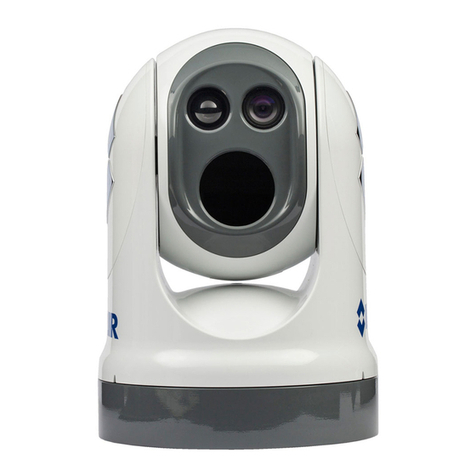
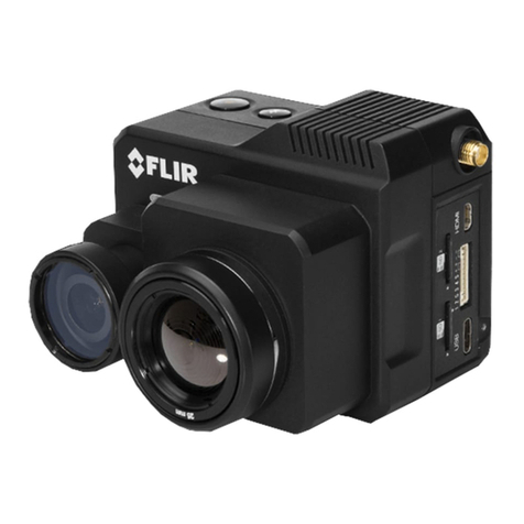
FLIR PTZ-35x140 User manual

PTZ-35x140 User’s Guide 427-0011-00-10 Version 100
PTZ-35x140™with Foveus™
Users Guide
427-0011-00-10
Version 100

PTZ-35x140 User’s Guide 427-0011-00-10 Version 100
Cautions and Warnings:
•Do not disassemble the PTZ-35x140™ enclosure. Disassembly can cause permanent
damage and will void the warranty.
•Operating PTZ-35x140™ outside of its specified operating temperature range or voltage
range can cause permanent damage and will void the warranty.
•Avoid pointing the device directly at extremely high-intensity radiation sources, such as the
sun, lasers, arc welders, etc. This warning applies whether or not the system is powered.
•Only clean the lens in the manner prescribed in the Appendix of this document.
•If you have questions that are not covered in this manual, or need service, contact FLIR
Support at 1-888-747-3547 for additional information.

PTZ-35x140 User’s Guide 427-0011-00-10 Version 100
TABLE OF CONTENTS
INTRODUCTION......................................................................................................................... 4
UNPACKING YOUR PTZ-35X140:........................................................................................... 4
QUICK-START INFORMATION.............................................................................................. 5
PELCO-D INTERFACE ....................................................................................................................... 6
NEXUS®CONSOLE INTERFACE .......................................................................................................... 9
PTZ-35X140™ PHYSICAL INTERFACE .............................................................................. 11
DIMENSION DRAWINGS.................................................................................................................... 11
SYSTEM INTERFACE CABLE CONNECTOR......................................................................................... 14
BREAK-OUT CONNECTOR CABLE .................................................................................................... 15
PTZ-35X140™ SPECIFICATIONS......................................................................................... 17
APPENDIX A: MAINTENANCE ............................................................................................. 19
LENS CLEANING............................................................................................................................... 19
HISTORY OF INFRARED ....................................................................................................... 20

PTZ-35x140 User’s Guide 427-0011-00-10 Version 100
INTRODUCTION
The PTZ-35x140™ is a versatile, dual field of view thermal and visible imaging system that
provides a high resolution thermal image with a 5° view nested inside a wider 20° view. This image
presentation concept derived from human vision offers excellent situational awareness and long
range threat detection, simultaneously. This advanced payload is packaged in a precision pan/tilt
enclosure that will slew up to 120° per second. The system supports stand-alone or network
operation with a Nexus® interface.
The PTZ-35x140™ incorporates the latest in visible and uncooled thermal imager performance with
both IP networked control and video connectivity for installation into sophisticated emerging
security infrastructures and serial and analog connectivity for current widely proliferated
infrastructures. The Foveus™ thermal imagery is provided as continually zoomed video from 20°
horizontal field of view to less than 1 degree horizontal field of view. The thermal imagery is
presented in a novel blending of two thermal images to provide high resolution in the critical 5°
center area while simultaneously providing medium resolution in the 20° situational awareness zone.
This presentation is an application of the design of the human eye, with the foveal region of the
retina employing higher density detectors than the peripheral area, thus the moniker Foveus™.
UNPACKING YOUR PTZ-35X140:
oPTZ-35x140 with Foveus 427-0011-XX
oBreak-Out Connector Cable (1 DB9 RS-422 and 1 DB9 Maintenance for communication, 1
BNC for composite video, 1 RJ45 Ethernet, terminal rings for power) 308-0117-00
oNexus® Console Software (unlimited copy rights)
Optional Accessories:
o40 ft System Cable 308-0116-02 (shown below)
o24V Power Supply 206-0004-01 (shown below)
oNexus® Console Joystick 223-0017-00 (shown below)

PTZ-35x140 User’s Guide 427-0011-00-10 Version 100
QUICK-START INFORMATION
The following instructions will get you started with basic operation of the PTZ-35x140™ with
Foveus™.
1. Firmly secure camera using mounting pattern shown below to a designated frame or
structure able to support and allow for device travel.
2. Connect System Cable into camera base shown above. Then attach the other end of the
sealed System Cable to the break-out pigtail.
3. If using the video output then plug a standard BNC cable to the connection labeled
“VIDEO P2” on the break-out pigtail.
4. If you intend to use the PELCO-D Interface for remote control of the device attach a
standard DB9 RS-422 cable to the connection labeled “USER P3” on the break-out pigtail.
Connect the other end of the RS-422 cable to an available port on remote control device
such as a KBD300. (Be sure to note that the pin settings are from the camera and must be
swapped on the controller device!) Pin settings are shown here below:
RS-422 DB9 Pin or “USER P3”
COM 1 Tx A (-) Signal OUT Pin 2
COM 1 Rx B (+) Signal IN Pin 3
COM GND Pin 5
COM 1 Tx B (+) Signal OUT Pin 7
COM 1 Rx A (-) Signal IN Pin 8

PTZ-35x140 User’s Guide 427-0011-00-10 Version 100
5. If you intend to use the Nexus® Console Software for both the remote control of the device
and video streaming attach a standard CAT5 cable to the connection labeled “ETHERNET
P5” on the break-out pigtail. Connect the other end to your PC.
6. Plug in either 24+/-10% VAC rms (50/60Hz) or 24+/-10% VDC directly to the connections
labeled “PTPWR” and “SYSPWR” on the break-out pigtail.
7. If purchased the Pelco WCS4-20 Master Power Supply will connect directly via
connections labeled “PTPWR” and “SYSPWR” on the break-out pigtail to the converter.
Connect the black leads to COM and the red leads to 24V. Next, adjust the AC Input
switch to either 115VAC (standard for US) or 230VAC (standard for Europe) and apply
power to the Pelco converter.
8. Now the PTZ-35x140™ is ready for use. Note that the device will immediately zero itself
and return back to home position upon applying power.
PELCO-D INTERFACE
The PTZ-35x140™ accommodates control via RS422. The command protocol for serial control
shall be via PELCO-D commands including the following minimum control set:

PTZ-35x140 User’s Guide 427-0011-00-10 Version 100
Table 1: Pelco D Command List
Also, refer to the User Controls for use with a Pelco KBD300A shown on the following page:
PTZ-35x140 Function KBD300 Pelco D Packet Pelco D Response
Pan/Tilt Drive Up FF 01 00 08 VV WW CK FF 01 00 CK
Down FF 01 00 10 VV WW CK FF 01 00 CK
Left FF 01 00 04 VV WW CK FF 01 00 CK
Right FF 01 00 02 VV WW CK FF 01 00 CK
UpLeft FF 01 00 0C VV WW CK FF 01 00 CK
UpRight FF 01 00 0A VV WW CK FF 01 00 CK
DownLeft FF 01 00 14 VV WW CK FF 01 00 CK
DownRight FF 01 00 12 VV WW CK FF 01 00 CK
Stop FF 01 00 00 VV WW CK FF 01 00 CK
Increments Focus closer Near button FF 01 01 00 00 00 02 FF 01 00 02
Increments Focus farther Far button FF 01 00 80 00 00 81 FF 01 00 81
Zoom In or Decreases FoV CW Joystick FF 01 00 20 00 00 21 FF 01 00 21
Zoom Out or Increases FoV CCW Joystick FF 01 00 40 00 00 41 FF 01 00 41
IR Polarity to Black Hot 1, Aux On FF 01 00 09 00 01 0B FF 01 00 0B
IR Polarity to White Hot 1, Aux Off FF 01 00 0B 00 01 0D FF 01 00 0D
Active Camera DLTV 2, Aux On FF 01 00 09 00 02 0C FF 01 00 0C
Active Camera IR 2, Aux Off FF 01 00 0B 00 02 0E FF 01 00 0E
Toggle: Plateau Values 3, Aux On FF 01 00 09 00 03 0D FF 01 00 0D
Toggle: AGC Type 3, Aux Off FF 01 00 0B 00 03 0F FF 01 00 0F
AutoFocus 4, Aux On FF 01 00 09 00 04 0E FF 01 00 0E
IR FFC 4, Aux Off FF 01 00 0B 00 04 10 FF 01 00 10
Toggle: LUT Palette 5, Aux Off FF 01 00 0B 00 05 11 FF 01 00 11
Toggle: AGC ROI 6, Aux On FF 01 00 09 00 06 10 FF 01 00 10
Toggle: Max Gain Value 7, Aux Off FF 01 00 0B 00 07 11 FF 01 00 11

PTZ-35x140 User’s Guide 427-0011-00-10 Version 100
User Controls for KBD300A
Keystrokes Function Toggle Values (default to first value)
Near button Focus Near
Far button Focus Far
AUX
ON
AUX
OFF
CW
Joystick Zoom In Increments from Wide to Tele
CCW
Joystick Zoom Out Increments from Tele to Wide NEAR FAR
1, Aux On IR Polarity to Black Hot
1, Aux Off IR Polarity to White Hot
2, Aux On Set DLTV as active For both commands and video
1 2 3
2, Aux Off Set IR as active For both commands and video
3, Aux On Toggle: Plateau Values
3, Aux Off Toggle: AGC Type
4 5 6
4, Aux On Autofocus One shot Autofocus
4, Aux Off IR FFC Internal calibration
7 8 9
5, Aux Off Toggle: LUT Palette White, Black
6, Aux On Toggle: DDE Gain Dynamic Detail Enhancement
CAM 0 CLEAR
6, Aux Off Toggle: AGC ROI Full, Horizon, Sky, Ground, Center
7, Aux Off Toggle: Max Gain
Values
Note: Must have the appropriate active camera to use associated camera functions.
To start type the Pelco Address (9,9) then CAM

PTZ-35x140 User’s Guide 427-0011-00-10 Version 100
NEXUS®CONSOLE INTERFACE
First install the Nexus®Console Software on your PC. The software installation procedure along
with PC hardware requirements is described in the README provided on the CD.
Next, create the proper Windows LOCAL User Group called Nexus Admin then assign the
group to the User you have logged in as (NOTE: Be sure to login and setup as LOCAL account
User versus a Guest setup for a domain or contact your System Administrator.) This is shown
below:
Below are the steps to remote control and stream video using the Nexus®Console:
1. Double click on Nexus®Icon on desktop and launch Nexus®.
2. Be sure to verify the IP address of the camera (Default is 192.168.250.116) and that your
PC and the camera are on the same subnet or have been routed correctly.
3. Select from the top menu pull-down Sensors->Add/Configure->Nexus Sensors.
4. Choose the white icon to “Add New Server Connection” then follow the options as
shown here below then select “ACCEPT”.
5. Once you have selected the corrected device then you can open the camera from the top
menu pull-down Sensors->Nexus->Open->”Camera Name” to view the following:

PTZ-35x140 User’s Guide 427-0011-00-10 Version 100
6. Be sure to select the “Control” (highlighted above) to establish control.
7. Next assign the joystick by selecting the Server Icon and right-click to “Assign Joystick”.
A orange rectangle box will appear on the Server Icon as shown below.
8. Next open a video channel by selecting the IR Camera Icon and right-click to open
Channel 1 for thermal as shown here:
9. Next do the same for DLTV Camera to open Channel 2 for daylight.
10. Now you are ready to use the PTZ-35x140 with the Nexus®Console!
You have now completed the basic steps for setup of the PTZ-35x140. However, it is
recommended that you read the rest of this User’s Guide.
For further instructions on Nexus® please refer to the Nexus®User’s Guide (Doc#428-0004-00-
10) or contact FLIR Support at 1-888-747-3547.

PTZ-35x140 User’s Guide 427-0011-00-10 Version 100
PTZ-35X140™ PHYSICAL INTERFACE
DIMENSION DRAWINGS The following figures show a dimensioned drawing of the PTZ-
35x140™.
Remember to firmly secure unit and allow for device travel.
Figure 1: PTZ-35x140™ swept dimensions

PTZ-35x140 User’s Guide 427-0011-00-10 Version 100
Figure 2: PTZ-35x140™ Dimension Drawing (inches)

PTZ-35x140 User’s Guide 427-0011-00-10 Version 100
Figure 3: PTZ-35x140™ Dimension Drawing w/ hole pattern (inches)

PTZ-35x140 User’s Guide 427-0011-00-10 Version 100
SYSTEM INTERFACE CABLE CONNECTOR The PTZ-35x140™uses an electrical-mechanical
engagement system that requires only one integrated cable to interface with the sensor. The
interface cable is 12.2 meters (40 ft) long and is terminated with a MIL-C-26482 Series 1
Connector. The table below describes the specifications:
MIL-C-26482 Series 1
Shell Size 18
Insert Arrangement 32
Finish Olive drab chromate
over cadmium
Contacts Pines
Shell Style Cable plug
Insert Position Keyring
Figure 4: PTZ-35x140™ Interface Cable Connector
Function Pin Signal Name Function Pin Signal Name
Power j Power In + Comms P3 M Tx(+) RS-422 (COM1)
f Power In + (USER) N Rx(+) RS-422 (COM1)
g Power In + c GND RS-422 (COM1)
W Power In + P Tx (-) RS-422 (COM1)
e Power In + R Rx (-) RS-422 (COM1)
b Power In - Comms P4 U Maintenance COM2
h Power In - (MAINT) S Maintenance COM2
Z Power In - V Maintenance COM2
a Power In - A Maintenance COM2
d Power In - T Maintenance COM2
Video K Video Out
J Video Out Shield
Chassis connector front view
(
Female
)
Interface cable connector front view
(
Male
)

PTZ-35x140 User’s Guide 427-0011-00-10 Version 100
BREAK-OUT CONNECTOR CABLE The PTZ-35x140™ also includes a break-out cable that
connects to the system interface cable with single terminal connectors. The break-out cable has
the MIL-C-26482 Series 1 Connector on one end and 4 pig-tail connectors and power leads of
the following:
Figure 5: Break-Out Connector Cable
Four terminal ring leads for power:
Input voltage range: 24 VDC ±10 % or 24 VAC ±10 % rms (50/60Hz). Nominal
static power consumption is <50W. The red are positive and the black are common
ground
One BNC video connector is used for both IR and DLTV video as shown here:
Analog video can be toggled using either the Pelco D commands or selected using
the Nexus Console.
Figure 6: IR/DLTV Video Output
One RJ45 connector is for Ethernet communication and streaming MPEG4 video:
Ethernet connection for use with the Nexus®provides both communications and
streaming video.
Figure 7: RJ45 Ethernet Connector

PTZ-35x140 User’s Guide 427-0011-00-10 Version 100
Streaming video can also be viewed using an off-the-shelf player such as Quicktime
or VLC from VideoLAN. Open a Network Stream then select RTSP and type the
camera IP address followed by the stream name (nfov = narrow field of view, wfov
= wide field of view and vis = visible) as follows: EX: rtsp://192.168.250.116/nfov
Figure 8: Video Streaming using VLC
Finally, two DB9 connectors are used for communication as shown here:
Communication via RS-422 with the connector labeled “P3” and the other is for
maintenance labeled “P4”. The protocol on “P3” is 422/Pelco D (see functions
listed in Table 1: Pelco D Command List)
Figure 9: RS-422 DB-9 (USER P3) Figure 10: DB-9 (Maintenance)
RS-422 DB9 Pin or “USER P3”
COM 1 Tx A (-) Signal OUT Pin 2
COM 1 Rx B (+) Signal IN Pin 3
COM GND Pin 5
COM 1 Tx B (+) Signal OUT Pin 7
COM 1 Rx A (-) Signal IN Pin 8

PTZ-35x140 User’s Guide 427-0011-00-10 Version 100
PTZ-35X140™ SPECIFICATIONS
•Power/Weight :
Input Voltage Range: 24 VDC ±10 % or 24 VAC ±10 % VAC rms (50/60Hz)
Sensor Weight w/o cable: 20411 g (45 lbs)
•Pan/Tilt Specifications:
Pan Tilt
Motion Range (°) Continuous ± 60
Angular Velocity (°/sec.) 0.1 to 120 0.1 to 120
Resolution (°) < 0.01 < 0.01
Accuracy (°) <0.1, 2 sigma <0.1, 2 sigma
Settling time (seconds) < 0.25 < 0.25
•Visible Camera Specifications:
oArray >740,000 pixels (PAL) and >630,000 pixels (NTSC)
oFOV Horizontal 54° to 2°, Optical
oFocus Automatic
oIris Automatic
oShutter Automatic
oBalance Automatic
oIR cut filter Automatic
oImage Stabilization
oDigital Zoom
oSpectral Response 400 to 750 nm with IR cut filter
•Infrared Camera Specifications:
Wide FOV 20° 35mm Narrow FOV 5° 140mm
Focal Plane Array Uncooled µbolometer Uncooled µbolometer
Format 320 x 240 320 x 240
Pixel Size 38µm 38µm
Aperture f/1.4 f/1.4
Field of View 20° HVOV x 15° VFOV 5° HVOV x 3.7° VFOV
Focus Athermalized One touch Auto Focus
Temporal NEdT ≤65 mK ≤65 mK
Range (man size) 560 meters 2200 meters

PTZ-35x140 User’s Guide 427-0011-00-10 Version 100
oFrame Rate 30 Hz
oSpectral Response 7.5µm to 13.5µm
•Environmental Requirements:
Caution: Sustained storage at high-temperature will degrade vacuum life of the camera core.
oStorage Temperature -50ºC to +85ºC
oOperating Temperature -32ºC to + 55ºC
oMoisture IP-66
oSand/Dust MIL-STD-810E, Method 510.3, procedure II
oVibration MIL-STD-810E, Method 514.4
oShock (transportation) 30g, 11 msec.
oEMI/EMC
CE Class A
FCC
oSolar Thermal Loading MIL-STD-810E, Method 505.3, procedure I, paragraph
1 3.2.b1
oExternal Icing MIL-STD-810E, Method 521.1, 6 mm ice thickness
oWind Load 50 mph
Note: These specifications are subject to change without notice. See the PTZ-35x140™
Specification (ISC doc. 427-0011-01-09) for detailed requirements.

PTZ-35x140 User’s Guide 427-0011-00-10 Version 100
APPENDIX A: MAINTENANCE
LENS CLEANING
Materials:
•Optical-grade tissue (e.g., Edmund Industrial Optics part number 52105 or any similar
product)
•pure water (de-ionized or other)
•isopropyl alcohol (IPA)
Procedure:
1. Saturate a piece of the lens tissue with the water and drape it over the lens. Let the
surface tension of the water pull the tissue onto the lens surface and then drag the tissue
across the lens surface. Repeat several times with different pieces of tissue.
2. Repeat the same step using IPA instead of water. Drag the final piece of tissue over the
lens several times to prevent pooling, which could leave a residue behind.

PTZ-35x140 Quick Start Guide 427-0011-00-12 Version 100
History of Infrared
Less than 200 years ago the existence of the infrared portion of the electromagnetic spectrum wasn't even suspected.
The original significance of the infrared spectrum, or simply ‘the infrared’ as it is often called, as a form of heat
radiation is perhaps less obvious today than it was at the time of its discovery by Herschel in 1800.
Sir William Herschel (1738–1822)
The discovery was made accidentally during the search for a new optical material. Sir William Herschel—Royal
Astronomer to King George III of England, and already famous for his discovery of the planet Uranus—was
searching for an optical filter material to reduce the brightness of the sun’s image in telescopes during solar
observations. While testing different samples of colored glass which gave similar reductions in brightness he was
intrigued to find that some of the samples passed very little of the sun’s heat, while others passed so much heat that
he risked eye damage after only a few seconds’ observation.
Herschel was soon convinced of the necessity of setting up a systematic experiment, with the objective of finding a
single material that would give the desired reduction in brightness as well as the maximum reduction in heat. He
began the experiment by actually repeating Newton’s prism experiment, but looking for the heating effect rather
than the visual distribution of intensity in the spectrum. He first blackened the bulb of a sensitive mercury-in-glass
thermometer with ink, and with this as his radiation detector he proceeded to test the heating effect of the various
colors of the spectrum formed on the top of a table by passing sunlight through a glass prism. Other thermometers,
placed outside the sun’s rays, served as controls.
As the blackened thermometer was moved slowly along the colors of the spectrum, the temperature readings
showed a steady increase from the violet end to the red end. This was not entirely unexpected, since the Italian
researcher, Landriani, in a similar experiment in 1777 had observed much the same effect. It was Herschel,
Table of contents
Other FLIR Thermal Camera manuals
Popular Thermal Camera manuals by other brands

PeakTech
PeakTech 5610 Operation manual

Chauvin Arnoux
Chauvin Arnoux C.A 1954 DiaCAm 2 quick start guide

Satir
Satir UMTI user manual

International Safety Instruments
International Safety Instruments Surveyor Owner's operation manual

Hikmicro
Hikmicro HM-TS03-15XF quick start guide

TESTO
TESTO 870 instruction manual