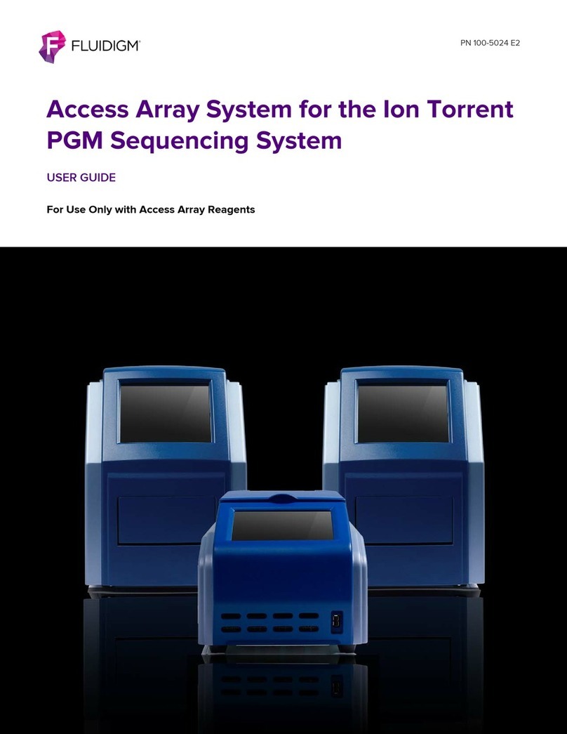
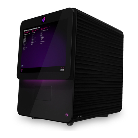
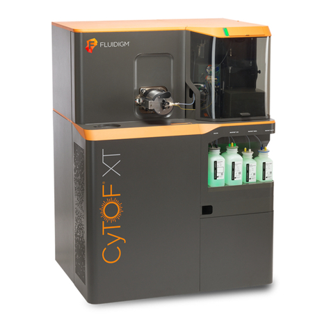
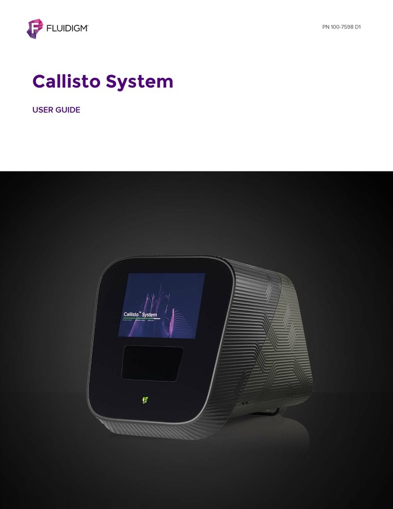
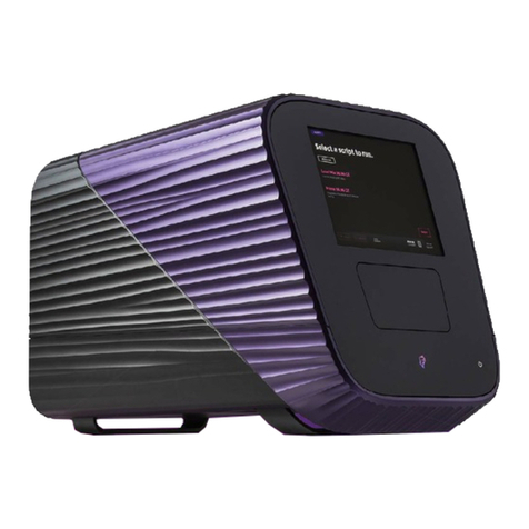
Fluidigm Hyperion User manual

Hyperion Imaging System User Guide 1
PN 400311 B1
Hyperion
Imaging System
User Guide

2Hyperion Imaging System User Guide
For Research Use Only. Not for use in diagnostic procedures.
Information in this publication is subject to change without notice. It is
Fluidigm policy to improve products as new techniques and
components become available. Therefore, Fluidigm reserves the
right to change specifications at any time. Every effort has been
made to avoid errors in the text, diagrams, illustrations, figures, and
screen captures. However, Fluidigm assumes no responsibility for
any errors or omissions. In no event shall Fluidigm be liable for any
damages in connection with or arising from the use of this
publication.
Patent and Limited License Information
Fluidigm products are covered by issued and pending patents in the
United States and other countries. Patent and limited license
information is available at 42T fluidigm.com/legalnotices42T.
Trademarks
Fluidigm, the Fluidigm logo, CyTOF, Helios, Hyperion, HTI, MCD, and
Maxpar are trademarks and/or registered trademarks of Fluidigm
Corporation in the United States and/or other countries. All other
trademarks are the sole property of their respective owners.
FACS is a registered trademark of Becton, Dickinson and Company.
For EU's WEEE directive information, go to 42Tfluidigm.com/compliance42T.
© 2019 Fluidigm Corporation. All rights reserved. 06/2019
Fluidigm Canada PN 400311 B1
IMC-QSG-02
For
technical support visit fluidigm.com/support.
North America
+1 650 266 6100 | Toll-free (US/CAN): 866 358 4354 | support.northamerica@fluidigm.com
Latin
Europe/Middle East/Africa/Ru
ssia +44 1223 598100 | support.europe@fluidigm.com
Japan
+81 3 3662 2150 | techsupportjapan@fluidigm.com
China (excluding Hong Kong)
+86 21 3255 8368 | [email protected]

Hyperion Imaging System User Guide 3
Contents
42TAbout This Guide42T
42TOperator Safety for the Hyperion Imaging System42T
42TSafety Alert Conventions42T
42TSafety Alerts for Chemicals42T
42TSafety Alerts for Instruments42T
42TSafety Data Sheets42T
42TChapter : Hyperion Imaging System
Introduction and Specifications42T
42TIntroduction42T
42T34BHyperion Imaging System Technology42T
42TSolid-State Laser Specifications42T
42THyperion Imaging System Specifications42T
42TStandard Equipment42T
42TRecommended Slide Dimensions42T
42TConsumables and Reagents42T
42T35BHyperion Imaging System42T
42THelios42T
42TChapter : Instrument Overview42T
42THyperion Tissue Imager42T
42T37BSample Window and Coupling Window42T
42THyperion Tissue Imager LED Panel42T
42TOther Components42T
42TChapter : Operation42T
42TConnect the Hyperion Tissue Imager to Helios42T
42TStart the Hyperion Imaging System42T
42TUnload and Load the Tuning Slide or Sample Slide42T
42TStart the Laser42T
42TDisconnect the Hyperion Tissue Imager from Helios42T
42TDisconnect Cables and Coupling Tube42T
42TSwitch to Cell Suspension Mode42T
42TChapter : Maintenance42T
42TCleaning Instructions42T
42T66BExterior Surfaces42T
42T67BInjector Cleaning42T
42T68BTorch Cleaning42T
42T69BCoupling Tube42T
42TPeriodic Maintenance42T
42T70BVacuum Interface Cones42T
42T71BReplace the Load Coil42T
42T72BReplace the Injector Sealer Cap42T
42T73BChange the Interface Pump Oil42T
42T74BChange the Oil on the Backing Pump42T
42TTroubleshooting42T
42TAppendix A: Decontamination42T
42TDecontamination of the Hyperion Imagaing System42T
42T81BBiological Agents42T
42T82BHazardous Chemicals42T
42T83BRadioactive Materials42T
42T84BDisposal of Products42T
42TAppendix B: Safety42T
42TGeneral Safety42T
42TLaser Safety for the Hyperion Tissue Imager42T
42TInstrument Safety42T
42TSymbols on the Instrument42T
42TElectrical Safety42T
42TChemical Safety42T
42TLaboratory Ventilation Safety42T
42TPressurized Gas Safety42T
42TSafe Handling of Gas Cylinders42T
42TSample Handling and Preparation Safety42T
42TRadio Frequency Radiation Safety42T

4Hyperion Imaging System User Guide
About This Guide
IMPORTANT Before using the system, read and understand the safety guidelines in this
document. Failure to follow these guidelines may result in undesirable effects, injury to
personnel, and/or damage to the system or to property.
Operator Safety for the Hyperion Imaging System
The Hyperion™ Imaging System is classified as a Class 1 laser device.
The laser radiation of the Class 1 laser system is eye-safe under all operating conditions.
This product includes lasers of a higher class whose beams are confined within a suitable
enclosure so that access to laser radiation is physically prevented.
Safety Alert Conventions
Fluidigm documentation uses specific conventions for presenting information that may
require your attention. Refer to the following safety alert conventions.
Safety Alerts for Chemicals
For hazards associated with chemicals, this document follows the United Nations Globally
Harmonized System of Classification and Labelling of Chemicals (GHS) and uses indicators
that include a pictogram and a signal word that indicates the severity level:
Indicator Description
Pictogram (see example) consisting of a symbol on a white background within a red
diamond-shaped frame. Refer to the individual safety data sheet (SDS) for the
applicable pictograms and hazards pertaining to the chemicals being used.
DANGER Signal word that indicates more severe hazards.
WARNING Signal word that indicates less severe hazards.

About This Guide
Safety Data Sheets
Hyperion Imaging System User Guide 5
Safety Alerts for Instruments
For hazards associated with instruments, this document uses indicators that include a
pictogram and signal words that indicate the severity level:
Indicator Description
Pictogram (see example) consisting of a symbol on a white background within a black
triangle-shaped frame. Refer to the system user guide for the applicable pictograms
and hazards pertaining to system usage.
9TDANGER Signal word that indicates an imminent hazard that will result in severe injury or death
if not avoided.
9TWARNING Signal word that indicates a potentially hazardous situation that could result in
serious injury or death if not avoided.
9TCAUTION Signal word that indicates a potentially hazardous situation that could result in minor
or moderate personal injury if not avoided.
9TIMPORTANT Signal word that indicates information necessary for proper use of products or
successful outcome of experiments.
Safety Data Sheets
Read and understand the SDSs before handling chemicals. To obtain SDSs for chemicals
ordered from Fluidigm, either alone or as part of this system, go to fluidigm.com/sds and
search for the SDS using either the product name or the part number.
Some chemicals referred to in this user guide may not have been provided with your
system. Obtain the SDSs for chemicals provided by other manufacturers from those
manufacturers.

6Hyperion Imaging System User Guide
Chapter 1: Hyperion Imaging System
Introduction and Specifications
Introduction
The Hyperion™ Imaging System is the world’s first and only commercially available
metal-tagged, antibody-directed Imaging Mass Cytometry™ (IMC™) platform that allows highly
multiplexed imaging with 135 available channels. The system is designed to detect
metal-tagged antibodies bound to proteins in biological samples using standard staining
methods. The platform can simultaneously detect 4 to 37 protein markers in biological
samples including fixed tissue sections or cells deposited onto glass slides (liquid biopsies).
This allows researchers to investigate cellular subpopulations in various tissue
microenvironments. The system allows for cellular profiling in spatial proximity, enabling
subpopulation profiling and exploration of relationships of neighboring cells within the
context of the tissue structure.
Figure 1. The Hyperion Imaging System.

Chapter 1: Hyperion Imaging System Introduction and Specifications
Introduction
Hyperion Imaging System User Guide 7
34BHyperion Imaging System Technology
The Hyperion Imaging System technology is an innovative system based on laser ablation
technology coupled with time-of-flight (TOF) mass cytometry of the resulting plume (see
Figures 2 and 3). The system uses a precisely directed laser beam focused at 1 µm to collect
protein markers stained with metal-tagged Maxpar® antibodies and directs these metal tags
for detection using CyTOF® technology. The sample on the slide is ablated and aerosolized.
The resulting aerosol plume is delivered through the coupling tube to the Helios™
inductively coupled plasma (ICP) torch through the argon and helium flow.
Figure 2. A glass slide containing a biological sample is loaded into the Hyperion Imaging System. The beam from
the solid-state laser is directed to the sample on the slide. The resulting plume is directed through the coupling
tube in a stream of argon gas towards the ICP Torch for CyTOF detection.

Chapter 1: Hyperion Imaging System Introduction and Specifications
Introduction
8 Hyperion Imaging System: User Guide
The slide is loaded onto the stage of the ablation chamber and the camera captures the
image from the slide. The system directs a laser beam through the optical components of
the chamber. The laser beam is focused to a 1 µm spot and ablates sample proteins stained
with metal-tagged antibodies on the slide, resulting in aerosol plumes. The plumes are
directed to the Helios ICP Torch, where they are vaporized, atomized, and ionized in the
plasma. The high-pass ion optics remove the low-mass ions that are not of analytical interest
before the ion cloud enters the TOF mass analyzer. The ions enter the TOF mass analyzer in
13 µs intervals (pushes). Ions are separated based on their mass-to-charge ratio and the
detector measures the quantity of each isotope for each plume, corresponding to a single
laser shot, from the sample based on differences in mass instead of wavelength, and at 1 Da
resolution with minimal background.
Acquired data are stored in an MCD file format. In a typical workflow one MCD file is used
for one sample slide which can contain multiple regions of interest (ROIs). MCD files can be
viewed with MCD™ Viewer software. MCD Viewer can also export acquired data as separate
images in a TIFF file format.
Figure 3. Schematic of the Hyperion Imaging System coupled with the Helios system.
86B81BPlume Transients
The material resulting from the laser shot that is directed to the sample slide is referred to as
the plume. The time it takes for a single plume generated as a result of a single laser shot to
be transferred to the Helios system, ionized, and then detected by the detector is defined as
the plume transient time. The duration of the single plume integration is defined as the
plume width. The default value for plume width at a frequency of 200 Hz is 384 pushes (see
Figure 4), which is approximately 5 milliseconds in duration. During manual tuning, the
software can generate a transient curve, which is displayed by opening the Transient
window in the software. When helium flow ramping is set up, the software graphs the dual
counts (number of ions) against time to determine the optimal helium flow required for
effective transient delivery to the Helios instrument with minimal crosstalk (or overlap of
plumes). Autotuning is recommended for optimizing helium flow.

Chapter 1: Hyperion Imaging System Introduction and Specifications
Solid-State Laser Specifications
Hyperion Imaging System User Guide 9
Figure 4. Graph of P
175
PLu intensity. The plume width of a single plume is represented as 384 pushes during 20 Hz
operation. A 20 Hz frequency is used to record and optimize transients during tuning.
Solid-State Laser Specifications
Table 1. Performance specifications for the solid-state laser
Description Performance Specifications
Laser type Nd:YAG
Wavelength nm
Energy output ≤ µJ
Repetition rate (frequency) // Hz

Chapter 1: Hyperion Imaging System Introduction and Specifications
Hyperion Imaging System Specifications
10 Hyperion Imaging System: User Guide
Hyperion Imaging System Specifications
Table 2. System specifications for the Hyperion Imaging System
Description System Specification
Tissue thickness (full ablation) ≤ µm thickness
Addressable sample size ≥ mm x mm
Scan area ≥ mmP
P/ Hr (@Hz)
Ablation spot size ≤%
Recommended operating temperature – °C
Optimal operating temperature ± °C
Table 3. Electrical specifications for the Hyperion Imaging System
Description Electrical Specifications
Power VA
Operating voltage – V AC
Operating frequency / Hz
Operating mode Single-phase operation
Power dissipation, full load < W
Table 4: Gas Specifications for the Hyperion Imaging System.
Gas
Specifications
Purity Pressure (psi) Flow Rate
(L/min)
Impurities (ppm)
Argon ≥.% ± Oxygen <
Nitrogen <
Hydrogen <
Water <
Helium ≥.%
Grade .
±NA Oxygen <.
Nitrogen <.
Hydrogen <.
Water <.

Chapter 1: Hyperion Imaging System Introduction and Specifications
Hyperion Imaging System Specifications
Hyperion Imaging System User Guide 11
Table 5. Instrument dimensions for the Hyperion Tissue Imager (HTI™)
Description Instrument Dimensions
Height cm ( in)
Width cm ( in)
Depth cm ( in)
Weight kg ( lb)

Chapter 1: Hyperion Imaging System Introduction and Specifications
Hyperion Imaging System Specifications
12 Hyperion Imaging System: User Guide
Table 6. Instrument dimensions for the Helios system
Decription Instrument Dimensions
Height cm ( in)
Width cm ( in)
Depth cm ( in)
Weight kg ( lb)
Table 7. Input and output connections for the Hyperion Imaging System
Description Input and Output Connections
Power AC power
Gases Argon gas, Helium gas
Sample Sample slide, ablated sample
Digital I/O USB . communication cable, USB . camera,
trigger (data acquisition card)
Table 8. Workstation specifications for the Hyperion Imaging System
Description Workstation Specifications
Operating system
Win Enterprise
Processor
EMB CORE i- @ .GHZ
Memory 32GB DDR4
Monitor LG® " Class : UltraWide® LED Monitor
Motherboard Intel®H110
Data storage OS: x GB SSD
Storage: x TB (RAID)

Chapter 1: Hyperion Imaging System Introduction and Specifications
Standard Equipment
Hyperion Imaging System User Guide 13
Standard Equipment
Table 9. Standard parts included in the Hyperion Imaging System shipment
Part Number Standard Equipment
Hyperion Imaging System, Helios system, Universal
computer, keyboard and mouse, Ultrawide LG® monitor
Hyperion Imaging System Package (Upgrade with
Hyperion Tissue Imager)*
*Upgrade for Helios customers only.
Recommended Slide Dimensions
Table 10. Recommended slide dimensions for the Hyperion Imaging System
Dimensions (mm)*
Width .–.
Length .–.
Thickness 0.8–1.7
* Recommendations are based on the size of the Hyperion Imaging System slide stage.
Consumables and Reagents
35BHyperion Imaging System
Table 11. Consumables available for the Hyperion Imaging System
Part Number Standard Equipment
108147 O-Ring, Coupling Tube—4 Pack
108480 Coupling Tube Kit
108174 Injector—Hyperion™ Tissue Imager
108168 Injector Nut
108286 Gas Connection Kit—Hyperion™ Tissue Imager
108650 Front and Back Ferrule Set—Hyperion™ Tissue Imager—5 Pack

Chapter 1: Hyperion Imaging System Introduction and Specifications
Consumables and Reagents
14 Hyperion Imaging System: User Guide
Table 12. Reagents available for the Hyperion Imaging System
Part Number Standard Equipment
3-Element Full Coverage Tuning Slide
Helios
Refer to the Helios User Guide (PN 400250).
Consumables Ordering
North America
Customers in the US and Canada who have a Fluidigm account are already registered for
online ordering. Go to 42T fluidigm.com/catalog42T. New customers can set up an online account to
place orders, view past order history, and see current order confirmations.
Phone: Toll-free (US/CAN) 866 358 4354
Outside North America
To reorder parts and reagents, contact your regional Fluidigm sales representative or
distributor. Go to fluidigm.com/contacts.

Hyperion Imaging System User Guide 15
Chapter 2: Instrument Overview
Hyperion Tissue Imager
WARNING Laser instruments generate potentially hazardous UV radiation. Do not
remove the top cover of the Hyperion™ Tissue Imager. Only a Fluidigm field service
engineer should remove the top cover and perform maintenance.
Top cover
Sample window
Wheel retraction
switch
I nt erlo ck L ED pa nel
Lower cover
Coupling tube
Coupling window
AC a nd
communication panel
Figure 5. Schematic of the Hyperion Tissue Imager side view

Chapter 2: Instrument Overview
Hyperion Tissue Imager
16 Hyperion Imaging System: User Guide
Ablation chamber
Coupling attachment
Coupling window
Figure 6. Schematic of the Hyperion Tissue Imager back view

Chapter 2: Instrument Overview
Hyperion Tissue Imager
Hyperion Imaging System User Guide 17
37BSample Window and Coupling Window
Closed Position
When the sample window or the coupling window is in the closed position, the light
corresponding to that window on the LED panel on the right side of the instrument is
GREEN.
Open Position
When the sample window or the coupling window is in the open position, the light
corresponding to that window on the LED panel on the right side of the instrument is NOT
LIT and the user cannot perform tuning or acquisition on the system.

Chapter 2: Instrument Overview
Hyperion Tissue Imager LED Panel
18 Hyperion Imaging System: User Guide
Hyperion Tissue Imager LED Panel
Table 13. Instrument Interlock LEDs on the LED panel of the Hyperion Tissue Imager
Instrument Interlock LED Description
COUPLING WINDOW When the light is green, the coupling window is
closed. When the light is not lit, the coupling
window is open and the interlock has been
triggered.
SAMPLE WINDOW When the light is green, the sample window is
closed. When the light is not lit, the sample window
is open and the interlock has been triggered.
CHAMBER PRESSURE When the light is lit, the chamber is pressurized.
LASER ENABLED When the light is amber, the laser is firing and
ready to ablate, or ablation is in progress.
LASER TEMP. When the light is red, the laser has exceeded safe
operating temperature. The laser will be disabled.
COUPLING TUBE When the light is lit, the coupling tube has been
connected to the ablation chamber. The wheel
retraction system is not activated.

Chapter 2: Instrument Overview
Hyperion Tissue Imager LED Panel
Hyperion Imaging System User Guide 19
Instrument Interlock LED Description
POWER When the light is continuously green, the system
power supplies are on. When light is not lit, the
system power supplies are off.
UPPER COVERS When the light is not lit, the upper cover housing
the optics and the laser has been removed.
HELIUM SUPPLY When the light is green, the pressure in the helium
supply line is within operating range.
COUPLING TUBE When the light is lit, the coupling tubing has been
connected to the ablation chamber. The wheel
retraction system is not activated.
INTERLOCK BYPASS When the light is flashing green, all safety
interlocks have been bypassed. (The interlock
bypass is for the field service engineering team.)
Torch box
Samp ler
cone
Vacuum
inter face
Figure 7. Interior view of the Helios™ instrument with front access door open

Chapter 2: Instrument Overview
Hyperion Tissue Imager LED Panel
20 Hyperion Imaging System: User Guide
RF fi ng ers
Front shi eld
Lo ad coi l
Torch body
Figure 8. Torch box
Table of contents
Other Fluidigm Laboratory Equipment manuals
Popular Laboratory Equipment manuals by other brands
Labconco
Labconco Purifier Logic+ 30132 Technical Manual and Specifications
IKA
IKA KS 4000 i control manual
Waters
Waters ACQUITY UPLC H-Class Series System guide

Hettich
Hettich UNIVERSAL 320 R Repair instructions
Philips
Philips PC-APD PW-1710 user manual

Daihan Scientific
Daihan Scientific VM-10 Operation manual

L2 Microwave
L2 Microwave BA00T60W15D-H operating manual
Thermo Scientific
Thermo Scientific SHKE8000 Series Operating and maintenance manual
Agilent Technologies
Agilent Technologies 5975T LTM GC Operation manual
BD
BD CSampler Plus installation quick reference guide
Siemens
Siemens Maxum II Reference manual

Metrohm
Metrohm 700 Dosino manual
