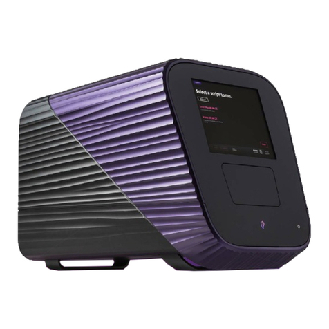
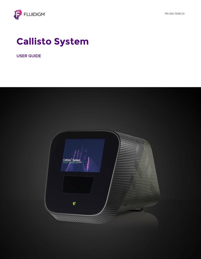
Fluidigm Polaris User manual

PN 100-9580 E1
Polaris
USER GUIDE

Polaris: User Guide
2
For technical support visit fluidigm.com/support.
North America +1 650 266 6100 | Toll-free (US/CAN): 866 358 4354 | techsupport@fluidigm.com
Japan +81 3 3662 2150 | techsupportjapan@fluidigm.com
China (excluding Hong Kong) +86 21 3255 8368 | techsupportchina@fluidigm.com
All other Asian countries/India/Australia +1 650 266 6100 | techsupportasia@fluidigm.com
For Research Use Only. Not for use in diagnostic procedures.
Information in this publication is subject to change without notice. It is
Fluidigm policy to improve products as new techniques and components
become available. Therefore, Fluidigm reserves the right to change
specifications at any time. Every effort has been made to avoid errors in
the text, diagrams, illustrations, figures, and screen captures. However,
Fluidigm assumes no responsibility for any errors or omissions. In no
event shall Fluidigm be liable for any damages in connection with or
arising from the use of this publication.
Patent and Limited License Information
Fluidigm products are covered by issued and pending patents in the
United States and other countries. Patent and limited license information
is available at fluidigm.com/legalnotices
Limited Use License to Perform Preamplification with Fluidigm IFCs
A license to use Thermo Fisher Scientific’s patented preamplification
method workflows involving a Fluidigm integrated fluidic circuit (IFC) can
be obtained (i) with purchase of a Fluidigm IFC from Fluidigm Corporation
or (ii) by a separate license from Thermo Fisher Scientific. For licensing
information, contact outlicensing@lifetech.com or Out Licensing, Thermo
Fisher Scientific, 5791 Van Allen Way, Carlsbad, CA 92008.
Limited Digital PCR License
A license to use Thermo Fisher Scientific’s patented digital PCR method
in all fields other than in the Sequencing Field, the Mass Spectrometry
Field, and the Prenatal Field in workflows involving a Fluidigm IFC can be
obtained (i) with purchase of a Fluidigm IFC from Fluidigm Corporation or
(ii) by a separate license from Thermo Fisher Scientific. For licensing
information, contact outlicensing@lifetech.com or Out Licensing, Thermo
Fisher Scientific, 5791 Van Allen Way, Carlsbad, CA 92008.
Trademarks
Fluidigm, the Fluidigm logo, C1, and Polaris are trademarks or
registered trademarks of Fluidigm Corporation in the United States and/
or other countries. All other trademarks are the sole property of their
respective owners.
For EU's WEEE directive information, go to fluidigm.com/compliance.
© 2018 Fluidigm Corporation. All rights reserved. 6/2018

Polaris: User Guide 3
Contents
Purpose 4
Safety Alert Conventions 4
Chapter 1: Introducing Polaris 6
Components of the Polaris System 7
Components Included in Shipping Box 10
Consumables Ordering 10
User Documentation 10
System Functions 11
Regulatory Compliance 11
General Regulations and Requirements 11
Harmonized Standards 11
Conformity Symbols on the Instrument 12
Chapter 2: Getting Started with Polaris 13
Start the Polaris System 13
The Polaris Touchscreen 15
The Polaris Menu 16
Begin with a New Experiment 17
Begin with an Existing Experiment 18
Set Up the Overview 19
Set Up the Prime Step 19
Set Up the Hemocytometer Step 20
Set Up the Cell Selection Step 24
Set Up the Sample Parameters 24
Set Up the Cell Population Parameters 25
Set Up Cell Selection Parameters for Each Channel 26
Set Up Cell Visibility Parameters for Each Channel 27
Set Up the Dose and Feed or Time Course Step 27
Set Up the Post Stain/Wash Step 31
Shut Down the Polaris System 32
Loading the IFC and EC IP into Polaris 32
Unloading the IFC and EC IP from Polaris 33
Skip, Pause, Stop, or Abort a Step on Polaris 34
Export Results to a USB Drive 34
Export a Debug Log to a USB Drive 35
View the Results Exported to the USB Drive 36
Appendix A: Troubleshooting 41
Powering ON/OFF 41
Loading 41
Running 42
Appendix B: Maintenance,
Decontamination, and Disposal 44
Cleaning and Maintenance 44
Preventative Maintenance Recommendations 44
Clean the Thermal Cycler Chuck 44
Clean the Environmental Control Interface Plate 45
Clean the Touchscreen 46
Decontamination and Disposal 46
Biological Agents 47
Hazardous Chemicals 47
Radioactive Materials 47
Disposal of IFCs 47
Fuse Replacement 48
Appendix C: Safety 49
General Safety 49
Instrument Safety 49
Instrument Symbols 50
Electrical Safety 51
Chemical Safety 51
Disposal of Products 51

Polaris: User Guide
4
About This Guide
IMPORTANT Before using the instrument, read and understand the safety guidelines in
this document and in the Site Requirements Guide (PN 100-9581). Failure to follow these
guidelines may result in undesirable effects, injury to personnel, and/or damage to the
instrument or to property.
Purpose
This guide describes how to use the Polaris™ System, including the instrument and system software. For
complete instrument specifications, see the Polaris Site Requirements User Guide (PN 100-9581).
Safety Alert Conventions
Safety Alerts for Chemicals
For hazards associated with chemicals, this document follows the United Nations Globally Harmonized
System of Classification and Labelling of Chemicals (GHS) and uses indicators that include a pictogram and
a signal word that indicates the severity level:
AZ
Indicator Description
Pictogram (see example) consisting of a symbol on a white background within a red
diamond-shaped frame. Refer to the individual safety data sheet (SDS) for the applicable
pictograms and hazards pertaining to the chemicals being used.
DANGER Signal word that indicates more severe hazards.
WARNING Signal word that indicates less severe hazards.

Polaris: User Guide 5
About This Guide
Safety Alert Conventions
Safety Alerts for Instruments
For hazards associated with instruments, this document uses indicators that include a pictogram and signal
words that indicate the severity level:
AZ
Safety Data Sheets
Read and understand the SDSs before handling chemicals. To obtain SDSs for chemicals ordered from
Fluidigm, either alone or as part of this system, go to fluidigm.com/sds and search for the SDS using either
the product name or the part number.
Some chemicals referred to in this user guide may not have been provided with your system. Obtain the
SDSs for chemicals provided by other manufacturers from those manufacturers.
Indicator Description
Pictogram (see example) consisting of a symbol on a white background within a black
triangle-shaped frame. Refer to the instrument user guide for the applicable
pictograms and hazards pertaining to instrument usage.
DANGER Signal word that indicates an imminent hazard that will result in severe injury or death
if not avoided.
WARNING Signal word that indicates a potentially hazardous situation that could result in serious
injury or death if not avoided.
CAUTION Signal word that indicates a potentially hazardous situation that could result in minor
or moderate personal injury if not avoided.
IMPORTANT Signal word that indicates information necessary for proper use of products or
successful outcome of experiments.

Polaris: User Guide
6
Chapter 1: Introducing Polaris
The Polaris™ system is a flexible microfluidics platform that allows you to perform
single-cell gene expression analysis. Under automated control, Polaris can image,
select, capture, culture, and dose single cells individually.
You can perform multi-step molecular biology protocols on the captured, single cells
and export the reaction products for further analysis. Thus, in situ single-cell analysis
can be combined with the study of alterations in the entire transcriptome or genome.
The Polaris instrument uses the Polaris Single-Cell Dosing mRNA Seq IFC. This IFC
(integrated fluidic circuit) captures 48 cells varying in size from 5 to 25 microns and is
capable of measuring responses to environmental changes by allowing treatment
and culturing of cells for up to 24 hours.
Follow the procedures in the document Polaris mRNA Seq Protocol (PN 101-0082),
which shows you how to select single cells; dose, feed, and/or treat them under
controlled environmental conditions; image targeted cells with fluorophore stains
(for example, to ensure cell viability); harvest their cDNA; and generate a cDNA
library for sequencing. You can see an example of the Results step for a Dose
Response experiment in Run: View the Results on page 35.
The following table is an example of fluorophores that can be used on Polaris:
Table 1. Examples of cell-staining dyes
Channel Name Excitation *
* Excitation values are center wavelength/pass band (≥90%).
Emission Recommended Stains
(FAM) 475/40 525/25 Alexa Fluor®488 (selection marker)
(VIC) 530/20 570/30 CellTracker™ Orange CMRA Dye (universal marker)
(Cy5) 632/28 700/30 Alexa Fluor 647 (selection marker)
(ZOMBIE)†
† Zombie Yellow is only for post section and treatment staining.
438/28 570/30 Zombie Yellow™ (dead cell dye)

Polaris: User Guide
Chapter1:IntroducingPolaris
Components of the Polaris System
7
Components of the Polaris System
Figure 1. Front of the Polaris instrument
Figure 2. Back of the Polaris instrument. There are also two USB 2.0 ports on the side of the
instrument.
Touchscreen interface
Retracted tray
Power & standby indicator
Compressed air inlet
ON/OFF switch & power socket
Display port (left) & Ethernet port (right)
USB ports
Premixed gas inlet

Polaris: User Guide
Chapter1:IntroducingPolaris
Components of the Polaris System
8
Figure 3. Open tray, exposing the EC IP above the IFC
The Environmental Control Interface Plate (EC IP) resides on top of the IFC and
provides an environment that is suitable for cell culture using user-desired gas
composition. Environmental parameters such as temperature, relative humidity, and
mix gas flow rate across the IFC are monitored and controlled.
Figure 4. The EC IP
Environmental Control
Tray
Status indicator
USB port (right side)
interface plate (EC IP)
Temperature and
humidity sensor
Rectangular
glass region

Polaris: User Guide
Chapter1:IntroducingPolaris
Components of the Polaris System
9
Figure 5. Open tray, exposing the EC IP (above the IFC that is not visible here)
The Polaris Single-Cell Dosing mRNA Seq IFC (integrated fluidic circuit) selects
single cells from heterogeneous cell samples and holds them in individual,
environmentally controlled reaction chambers. For more information about the
reagents and cells for this IFC, see the Polaris mRNA Seq Protocol (PN 101-0082).
Figure 6. The Polaris Single-Cell Dosing mRNA Seq IFC
Figure 7. Open tray, exposing the notched corner of the IFC
Environmental Control
interface plate (EC IP)
A1
Notched corner

Polaris: User Guide
Chapter1:IntroducingPolaris
Components Included in Shipping Box
10
Components Included in Shipping Box
NOTE To order additional items, contact Fluidigm sales. For phone or email contact
information, go to fluidigm.com.
Consumables Ordering
To reorder IFCs and Fluidigm reagents, contact your regional Fluidigm sales
representative or distributor. Go to fluidigm.com/contact.
User Documentation
The latest Polaris documentation is available for download at
fluidigm.com/documents.This documentation is also available by request. Contact
Technical Support for assistance.
Component Description Qty
1 Polaris system
(PN 100-9009)
Selects, cultures, and captures single cells, with the capability to dose,
image, and perform multi-step molecular biology protocols on each cell
individually, and to export the reaction products.
1
2 Power cable, >10 A 2m
IEC C13 (PN 59000376)
Country-specific power cable to connect the Polaris instrument to the wall
socket
The instrument has a connection to protective earth through the
power cord provided by Fluidigm. Ensure that the electrical
receptacle provides an earth ground before connecting the
power cord.
Use only power cords provided by Fluidigm or power cords that meet the
minimum ratings of 250V/10A, 16AWG and a length not exceed 2 meters
(6 feet).
1
3 Interface Plate Storage
Container with EC IP
The Environmental Control Interface Plate (EC IP) rests above the IFC in the
tray and has temperature and humidity sensors.
1
4 Spare EC IP filters,
sponge, and sponge
holder
Small packet for use with the EC IP
5 Hemocytometer plate Holds a user-provided, two-chamber hemocytometer that allows you to
optimize the fluorescence levels of cell markers.
6 1/4 inch tubing, 50 feet Connects your CDA system to the compressed air inlet on the back of the
Polaris instrument and connects the gas tank to the premixed gas inlet on
the back of the Polaris instrument.

Polaris: User Guide
Chapter1:IntroducingPolaris
System Functions
11
System Functions
The Polaris system:
•Actively selects and isolates targeted cells.
•Controls the environment of the cells, including temperature, gas levels, humidity,
dosage, and exposure.
•Automatically feeds cells, removes waste, and adds reagents.
•Images cells to ensure phenotype and cell viability.
•Challenges cells with a wide range of potential factors, including RNAs,
transcription factors, viruses, and more.
•Prepares individual cells for mRNA sequencing.
The LCD display is a touchscreen that allows you to design experiments quickly, set
up the instrument for use, and monitor progress during the current run.
Regulatory Compliance
The following directives and harmonized standards were used to evaluate the safety
and performance of the Polaris system:
General Regulations and Requirements
•2014/35/EU European Parliament Low Voltage Directive
•2014/30/EU European Parliament Directive: Electromagnetic Compatibility
Harmonized Standards
•IEC/EN 61326-1
•IEC/EN 61326-2-1
•IEC/EN 61010-1
•IEC/EN 61010-2-010
•IEC/EN 61010-2-081
•UL Standard Number 61010-1 2nd Edition
•CAN/CSA-C22.2 No. 61010-1-04
•CAN/CSA-C22.2 No. 61010-2-010-04
•CAN/CSA-C22.2 No. 61010-2-010-081-04

Polaris: User Guide
Chapter1:IntroducingPolaris
Regulatory Compliance
12
Conformity Symbols on the Instrument
Refer to the Polaris System Site Requirements Guide (PN 100-9581) for more detailed
information on the recommended environmental conditions.
Conformity mark Description
Indicates conformity with European Union requirements for safety and electromagnetic
compatibility.
Indicates conformity with North American requirements for safety and electromagnetic
compatibility.

Polaris: User Guide 13
Chapter 2: Getting Started with Polaris
This chapter shows you how to start and set up the Polaris™ instrument to image,
select, capture, and dose or culture single cells individually.
Start the Polaris System
1Plug the power cable into the power socket. Connect to the network.
The instrument has a connection to protective earth through the power
cord provided by Fluidigm. Ensure that the electrical receptacle provides an
earth ground before connecting the power cord.
1Power ON the switch on the back of the Polaris system.
Compressed air inlet
ON/OFF switch & power socket
Display port (left) & Ethernet port (right)
USB ports
Premixed gas inlet

Polaris: User Guide
Chapter 2: Getting Started with Polaris
Start the Polaris System
14
The first screen that you see displays the initialization screen for roughly 10 to 15
seconds while all the system components are initializing:
When initialization is complete, you see the next screen, which allows you to select
an experiment to run:

Polaris: User Guide
Chapter 2: Getting Started with Polaris
The Polaris Touchscreen
15
The Polaris Touchscreen
The LCD display is an interactive touchscreen that allows you to design experiments
quickly, set up the instrument for use, and monitor progress during the current run.
To access areas that are outside the current area on display, use your fingers and
swipe to the right or left. You can also tap the left-most or right-most edges of the
touchscreen to scroll to the left or right.

Polaris: User Guide
Chapter 2: Getting Started with Polaris
The Polaris Menu
16
The Polaris Menu
The Polaris menu is accessible before you begin the Prime step and after you exit
the Results step:
This menu allows you to create new experiments; view, export, or clone
experiments; use the hemocytometer outside the workflow; and access utilities that
are pertinent to your site. For example, you can open the door and eject the tray (for
example, to insert or remove the IFC or clean the EC IP), tap Utilities, and then tap
Open Tray. When you are done, tap Close.
To access the menu, tap this Fluidigm icon (on the bottom-left of the touchscreen):
To close the menu, tap the screen anywhere outside of the menu.
To start the screensaver, tap the lock icon at the bottom-right of the touchscreen,
adjacent to the IP address and time and date of the session:
To return to the original touchscreen size, tap it again or press the Esc key on your
keyboard.

Polaris: User Guide 17
Setting Up the Experimental Run
On Polaris, you can begin the experimental run using:
•A new experiment. Create a single-cell mRNA Seq experiment from scratch that
contains a new experiment profile for one of 3 types of experiments (Dose and
Feed, Time Course, or No Treatment), and then run the experiment.
•An existing experiment. Clone an existing experiment, edit the experiment profile
as needed, and then run edited experiment as a new experiment. (Alternatively,
you can rerun an existing experiment without any editing.)
For more information on how to run an mRNA Seq experiment, see the section
Running a Single-Cell mRNA Seq Experiment on Polaris in the Polaris mRNA Seq
Protocol (PN 101-0082).
Begin with a New Experiment
1Tap the Fluidigm logo at the bottom-left of the touchscreen:
2When you see the Polaris menu on the left panel, tap New Experiment.
3On the Select an experiment to run screen, tap the type of experiment that you
want to run. You can set up and run one of the three built-in types of experiments on
single cells in 48 cell capture sites:
•Dose and Feed. In a Dose and Feed experiment, the 48 capture sites are
segregated into 8 groups of 6 cells each, and each group of cells can be exposed
to a different dosing reagent. You also have the ability to feed all the capture sites
from a single medium source before and/or after the Dose and Feed step to allow
cells to equilibrate to their environment before or after dosing. Dosing and
feeding times are flexible but occur simultaneously for all 48 capture sites. The
shortest possible dosing or feeding interval is 10 minutes, and the longest is 24
hours.
•Time Course. In a Time Course experiment, the 48 capture sites are segregated
into 6 groups of 8 cells each. Each group of cells is exposed to the same dosing
reagent at its defined start time over the course of the experiment to study the
cellular response to treatment over time. Dosing and feeding parameters are
flexible and can occur at different, user-defined intervals for each group. The

Polaris: User Guide
Setting Up the Experimental Run
Begin with an Existing Experiment
18
shortest possible dosing or feeding interval is 20 minutes, and the longest is 24
hours.
•No Treatment. In a No Treatment experiment, the Cell Selection step is followed
immediately by the Post Stain/Wash step, by-passing the Dose and Feed or Time
Course step entirely.
4You are now ready to enter the experimental profile, beginning with Set Up the
Overview on page 19 and continuing with each step in the workflow.
Begin with an Existing Experiment
1Tap the Fluidigm logo at the bottom-left of the touchscreen:
2When you see the Polaris menu on the left panel, tap View Runs.
3On the Select a run to view screen, you can see your previous experimental setups
and export completed run data (including capture annotation, intensities, and
images).
The latest runs are on display in the touchscreen. Use the locater bar to display the
experimental run of your choice. For example:
The most current run is located at the far left, and all previous runs follow to the right.
Either use your fingers to swipe to the right or left or tap any of the navigation bars,
and then swipe to the right or left to display the experiments that reside within that
set.
This example contains 40 runs. Run 1 is the most current run (on display at the far left
of the touchscreen) and run 40 is the oldest run (at the far right of all the runs).
4Tap an experiment that you want to clone.
5Tap Clone.
6On the Experiment details screen, you can edit the existing experimental profile,
and then tap Start to run the experiment.
7You are now ready to edit the existing experimental profile, beginning with Set Up
the Overview and continuing with each step in the workflow.

Polaris: User Guide
Setting Up the Experimental Run
Set Up the Overview
19
Set Up the Overview
Beneath the Overview area, you can tap the large gray box and enter a description
of the experiment to be run. A description can be added or changed at any time
during the run.
Set Up the Prime Step
The Prime step allows you to specify whether the cells will be maintained in
suspension (default) or adherent conditions.
The Adherent Cell Priming option requires the use of an additional inlet for loading
the extracellular matrix (ECM) of your choice, which coats the capture sites and
permits adherent cell attachment. Suspension cell priming does not include an extra-
cellular matrix coating step.
1To change the experiment details for the Prime step to adherent cells, tap
Suspension Cell Priming beneath Prime:
2The lower area of the screen appears that allows you to make the change. Tap
Suspension Cell Priming in the Priming Type box to change the value to Adherent
Cell Priming:
This action also changes the display of the Prime step to Adherent Cell Priming:

Polaris: User Guide
Setting Up the Experimental Run
Set Up the Hemocytometer Step
20
Set Up the Hemocytometer Step
The hemocytometer on Polaris allows you image cells to measure the fluorescence
levels of cell markers. You can image cells at the Hemocytometer step during the run
(see Image Cells with the Hemocytometer on page 24). You can also image cells on
Polaris outside the run. This on-instrument procedure uses the user-provided two-
chamber INCYTO C-Chip™ Disposable Hemocytometer (Neubauer Improved, PN
DHC-N01). One chamber will contain a fluorescent reference bead suspension and
the other will contain the fluorescent stained cells.
IMPORTANT The Hemocytometer feature is available for use only if you have a
USB key with at least 3 GB of storage in the USB port.
Place the hemocytometer into the hemocytometer holder and place the holder into
the Polaris tray with the notch facing toward you on the front-left side, and then place
the EC IP over the top of the hemocytometer (EC IP not shown here):
Hemocytometer
Hemocytometer holder
Sampling area Detection area
Sample injection area
Table of contents
Other Fluidigm Laboratory Equipment manuals
Popular Laboratory Equipment manuals by other brands
Thermoline Scientific
Thermoline Scientific TELR 130 instruction manual
Neuation
Neuation iFUGE M08 Product user manual

BANDELIN
BANDELIN SONOREX TECHNIK W 65 Instructions for use

GE
GE ReadyToProcess WAVE 25 operating instructions

Sigma
Sigma spectrum Quick reference guide
Resodyn
Resodyn OmniRAM installation manual
Koehler
Koehler K34710 Operation and instruction manual
Optipette
Optipette OP2 manual
Harvard Bioscience
Harvard Bioscience BTX Oocyte Petri Electrode 45-2059 user manual

VERDER
VERDER Carbolite Gero GP 330 Installation, operation and maintenance instructions
Shimpo
Shimpo RK-3D instruction manual
BIO RAD
BIO RAD Experion DNA 12K analysis kits quick guide
