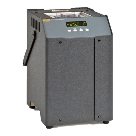
Fluke 9100 Series Instruction Manual

Final Width = 215mm
U
SER
'
S
H
ANDBOOK
Model 9100
Universal Calibration System
Volume 2 — Performance

User's Handbook
For
The Model 9100
Universal Calibration System
(for Introduction, Installation, Controls (with Tutorial), Manual Mode and Procedure Mode
refer to Volume 1 — Operation)
(for Options 250 and 600 refer to Volume 3 — Operation and Performance)
Volume 2 — Performance
ISO 9002
© 2007Fluke Corporation. All rights reserved.
All product names are trademarks of their respective companies.

This product complies with the requirements of the following European Community Directives:
89/336/EEC (Electromagnetic Compatibility) and 73/23/EEC (Low Voltage)
as amended by 93/68/EEC (CE Marking).
However, noisy or intense electromagnetic fields in the vicinity of the equipment can disturb the measurement
circuit. Users should exercise caution and use appropriate connection and cabling configurations to avoid
misleading results when making precision measurements in the presence of electromagnetic interference.
© 2007Fluke Corporation P/N 850301Issue 11.0(July 2007)

0-2 Model 9100 User's Handbook — Contents List
Page
Final Width = 215mm
Contents
Section 1 The Model 9100 Multifunction Calibrator See Volume 1 - Operation
Section 2 Installing the Model 9100 See Volume 1 - Operation
Section 3 Model 9100 Controls See Volume 1 - Operation
Section 4 Using the Model 9100 — Manual Mode See Volume 1 - Operation
Section 5 Using the Model 9100 — Procedure Mode See Volume 1 - Operatio
Volume 2 — Performance (
This Volume
)
Section 6 Remote Interfaces
6.1 About Section 6 ................................................................................................ 6-1
6.2 Index of IEEE-488.2 and SCPI Codes used in the Model 9100 ....................... 6-2
6.3 Introduction....................................................................................................... 6-4
6.4 Using the Model 9100 in a System................................................................... 6-8
6.5 Retrieval of Device Status Information ............................................................. 6-15
6.6 Model 9100 SCPI Language - Commands and Syntax.................................... 6-24
6.7 The IEEE Bus Interface for the Power Option .................................................. 6-58
Section 6 Appendix A: IEEE 488.2 Device Documentation Requirements............... 6-A1
Section 6 Appendix B: SCPI Conformance Information ........................................... 6-B1
Section 6 Appendix C: IEEE 488.2 Common Commands and Queries
Implemented in the Model 9100 ........................................... 6-C1
Section 6 Appendix D: Model 9100 — Device Settings after *RST .......................... 6-D1
Section 6 Appendix E: Model 9100 — Device Settings at Power On ....................... 6-E1
Section 7 Model 9100 Specifications
7.1 General............................................................................................................. 7-1
7.2 Options and Associated Products .................................................................... 7-2
7.3 DC Voltage Specifications ................................................................................ 7-3
7.4 AC Voltage Specifications ................................................................................ 7-4
7.5 DC Current Specifications ................................................................................ 7-8
7.6 AC Current Specifications ................................................................................ 7-9
7.7 Resistance Specifications ................................................................................ 7-14
7.8 Conductance Specifications ............................................................................. 7-15
7.9 Frequency Function Specifications .................................................................. 7-16
7.10 Mark/Period Function Specifications ................................................................ 7-17
7.11 % Duty Cycle Function Specifications .............................................................. 7-18
7.12 Auxiliary Functions - Specifications .................................................................. 7-19
7-13 Capacitance Specifications .............................................................................. 7-20
7.14 Thermocouple Temperature Specifications...................................................... 7-21
7.15 RTD Temperature Specifications ..................................................................... 7-22
7.16 Logic-Pulses Function Specifications ............................................................... 7-23
7.17 Logic-Levels Function Specifications ............................................................... 7-24
7.18 Insulation/Continuity Specifications .................................................................. 7-25
7.19 Power Specifications ........................................................................................ 7.27

Model 9100 User's Handbook — Contents List 0-3
Page
Final Width = 215mm
Section 8 Model 9100 — Routine Maintenance and Test
8.1 About Section 8 ................................................................................................ 8-1
8.2 Routine Maintenance ....................................................................................... 8-2
8.3 Model 9100 Test and Selftest........................................................................... 8-10
8.4 Printing Selftest Results ................................................................................... 8-26
Section 8 Appendix A Error Reporting Subsystem .................................................. 8-A1
Section 9 Model 9100 — Specification Verification
9.1 About Section 9 ................................................................................................ 9-1
9.2 The Need for Verification.................................................................................. 9-1
9.3 Equipment Requirements ................................................................................. 9-2
9.4 Interconnections ............................................................................................... 9-2
9.5 Verification Points............................................................................................. 9-3
9.6 Calculating Absolute Specification Limits ......................................................... 9-4
Section 10 Model 9100 — Calibration
10.1 About Section 10 .............................................................................................. 10.1-1
10.2 The Model 9100 Calibration Mode ................................................................... 10.2-1
10.2.1 Introduction ....................................................................................... 10.2-1
10.2.2 Mode Selection ................................................................................. 10.2-2
10.2.3 Selection of Calibration Mode ........................................................... 10.2-2
10.2.4 Special Calibration ............................................................................ 10.2-5
10.2.5 Cold Junction Calibration .................................................................. 10.2-8
10.2.6 Standard Calibration ......................................................................... 10.2-12
10.2.7 Overview of Calibration Operations .................................................. 10.2-14
10.3 Standard Calibration — Basic Sequences ....................................................... 10.3-1
10.3.1 Introduction ....................................................................................... 10.3-2
10.3.2 Selecting Hardware Configurations................................................... 10.3-4
10.3.3 Selecting Target Calibration Values .................................................. 10.3-5
10.3.4 Calibrating the Model 9100 at Target Values .................................... 10.3-9
10.3.5 Standard Calibration of AC Functions ............................................... 10.3-13
10.4 Front Panel Calibration by Functions ............................................................... 10.4-1
10.4.1 Introduction ....................................................................................... 10.4-1
10.4.2 Summary of Calibration Process....................................................... 10.4-2
10.4.3 DC Voltage Calibration...................................................................... 10.4-6
10.4.4 AC Voltage Calibration ...................................................................... 10.4-14
10.4.5 DC Current Calibration ...................................................................... 10.4-20
10.4.6 AC Current Calibration ...................................................................... 10.4-28
10.4.7 Resistance Calibration ...................................................................... 10.4-36
10.4.8 Capacitance Calibration .................................................................... 10.4-45
10.4.9 Insulation Resistance Calibration ...................................................... 10.4-51
10.4.10 Continuity Calibration ........................................................................ 10.4-57
10.5 Remote Calibration of the Model 9100 via the IEEE 488 Interface .................. 10.5-1
10.5.1 The Model 4950 MTS System........................................................... 10.5-1

Final Width = 215mm
DANGER
HIGH VOLTAGE
DANGER
!
Model 9100: I+, I-, Hi, Lo, sHi and sLo Terminals
Model 9105: H (Red), sH (Red), sL (Black) LI- (Black)
and I+20 (Yellow) Leads carry the Full Output Voltage
THIS CAN KILL !
Avoid damage to your instrument !
Refer to User's Handbook, Volume 2, Section 7; for
Maximum Output Voltages and Currents.
Unless you are sure that it is safe to do so,
DO NOT TOUCH ANY of the following:
Model 9100:I+ I- Hi Lo sHi or SLo leads and terminals
Model 9105:H sH sL LI-or I+20 leads
THIS INSTRUMENT IS CAPABLE OF DELIVERING
A LETHAL ELECTRIC SHOCK !
!

Section 6: 9100 System Operation — SCPI Language 6-1
Final Width = 215mm
Section 6: 9100 System Application via IEEE-488 Interface
6.1 About Section 6
Section 6 describes the environment in which the Model 9100 will operate in remote
applications, using the SCPI (Standard Commands for Programmable Instruments)
language, within the IEEE-488.1 remote interface. In Section 6 we shall show how the
9100 adopts the IEEE-488.2 message-exchange model and reporting structure, and
definethe SCPIcommandsand syntaxused tocontrolthe 9100. Section6 isdividedinto
the following sub-sections: page:
6.2 Index of IEEE-488.2 and SCPI Codes used in the 9100...............................6-2/3
6.3 Introduction
9100 System Operational Parameters.
6.3.1 Interface Capability. ........................................................................ 6-4
6.3.2 Interconnections. ............................................................................. 6-6
6.3.3 SCPI Programming Language. ....................................................... 6-7
6.4 Using the 9100 in a System
9100 System — Infrastructure.
6.4.1 Addressing the 9100. ...................................................................... 6-8
6.4.2 Operation via the IEEE-488 Interface. ........................................... 6-10
6.4.3 Message Exchange. ......................................................................... 6-12
6.4.4 Request Service (RQS). .................................................................. 6-14
6.5 Retrieval of Device Status Information.
9100 'SCPI' Status Reporting Structure, based on IEEE-488.2.
6.5.1 General. ........................................................................................... 6-15
6.5.2 IEEE-488 and SCPI Standard-Defined Features. ...........................6-17
6.5.3 9100 Status Reporting — IEEE-488.2 Basics. ............................... 6-18
6.5.4 9100 Status Reporting — SCPI Elements. ..................................... 6-23
6.6 9100 SCPI Language — Commands and Syntax.
Detailed treatment of the 9100 SCPI Command Set
6.6.1 Introduction. .................................................................................... 6-24
6.6.2 CALibration Subsystem .................................................................. 6-25
6.6.3 OUTPut Subsystem. ........................................................................ 6-28
6.6.4 SOURce Subsystem. ....................................................................... 6-30
6.6.5 STATus Subsystem. ........................................................................ 6-49
6.6.6 SYSTem Subsystem. ...................................................................... 6-53
Appendix A: IEEE 488.2 Device Documentation Requirements. ................. 6-A1
Appendix B: SCPI Command Set & Conformance Information...................6-B1
Appendix C: IEEE 488.2 Common Commands and Queries........................6-C1
Appendix D:
∗
RST (Reset) Conditions. .........................................................6-D1
Appendix E: Power-on Conditions. .............................................................. 6-E1

6-2 Section 6: 9100 System Operation — SCPI Language
Final Width = 215mm
6.2 Index of IEEE 488.2 and SCPI Codes used in the 9100
Program Coding Description Appendix C, Page:
∗CLS Clears event registers and queues (not O/P queue) 6-C1
∗ESE Nrf Enables standard-defined event bits 6-C2
∗ESE? Returns ESE register mask value 6-C2
∗ESR? Reads Event Status register 6-C3
∗IDN? Reports manufacturer, model, etc. 6-C4
∗OPC Sets the 9100 to monitor the 'No-Operations-Pending' flag. 6-C5
∗OPC? For 'No-Operations-Pending' flag 'TRUE', places a 1 in the Output Queue. 6-C5
∗OPT? Recalls the instrument's option configuration. 6-C6
∗PSC 0/1 Sets/resets power-on status clear flag 6-C7
∗PSC? Recalls power-on status clear flag 6-C8
∗PUD Allows entry of user data to protected store 6-C9
∗PUD? Recalls user-entered data 6-C10
∗RST Resets instrument to power on condition 6-C11 / App D, p6-D1
∗SRE Nrf Enables Service Request Byte bits 6-C11
∗SRE? Returns Service Request Byte mask value 6-C12
∗STB? Non-destructively reads Service Request Byte 6-C12
∗TST? Perform Full Test 6-C13
∗WAI Conforms, but little relevance to 9100 application 6-C14
6.2.1 Common IEEE 488.2 Commands and Queries

Section 6: 9100 System Operation — SCPI Language 6-3
Final Width = 215mm
6.2.2 9100 SCPI Subsystems
CALibration Used to calibrate the functions and hardware ranges of the 9100, correcting for system errors which have
accumulated due to drift and ageing effects:........................................................................................................................6-25
SECure :PASSword. Gains access to Calibration operations, using 'Cal Enable' switch and Password.
:EXIT. Permits clean exit from calibration operation .....................................................................6-25
TARGet Sets up the calibration target point, hardware range (and frequency, where required). ................6-26
TRIGger? Initiates the calibration at a single point, once the target and levels have been set up,
and returns '0' for pass, and '1' for fail............................................................................................6-27
SPECial? Runs the DAC characterization and returns '0' for pass, and '1' for fail .........................................6-27
CJUNction? Runs the reference thermocouple junction temperature measurement
and returns '0' for pass, and '1' for fail............................................................................................6-27
OUTPut Used to control parameters associated with output connections: ........................................................................................ 6-28
[STATe] (?) Controls output on/off switching ..................................................................................................... 6-28
COMPensation (?) Switches the output connections for 4-wire/2-wire in impedance functions ................................... 6-28
ISELection (?) For Current outputs, selects between front panel terminals (High currents, Current coils), and
front panel D-type Socket (Low currents).......................................................................................6-29
[SOURce] Used to select the main 9100 Function (Voltage, Current etc.), to be output:...................................................................... 6-30
FUNCtion Selects the Waveshape of output signals ......................................................................................6-32
VOLTage Selects the Voltage source for output ............................................................................................ 6-34
CURRent Selects the Current source for output ............................................................................................ 6-36
RESistance Selects the Resistance source for output.......................................................................................6-37
CONDuctance Selects the Conductance source for output ................................................................................... 6-38
CAPacitance Selects the Capacitance source for output .................................................................................... 6-39
FREQuency Controls the Output Frequency value for AC functions ..................................................................6-40
PHASe Selects and controls the Phase-shifting facility ..............................................................................6-41
PULSe Selects and controls the Pulse source for output ...........................................................................6-43
TEMPerature Selects and controls the Temperature sources for output ............................................................. 6-44
STATus Gives access to the 9100 SCPI-defined Status Reporting Structure: .................................................................................. 6-49
OPERation Reads from, or writes to, the OPERation Status Register ............................................................. 6-49
QUEStionable Reads from, or writes to, the QUEStionable Status Register......................................................... 6-51
PRESet Presets a default status reporting condition ...................................................................................6-52
SYSTem Collects general functions that are not related to 9100 performance: ..................................................................................6-53
ERRor? Requests the next entry from the 9100 error queue. ..................................................................... 6-53
DATE(?) Reads or writes the present date ...................................................................................................6-54
TIME(?) Reads or writes the present time ................................................................................................... 6-55
SVOLtage(?) Reads or writes the Safety Threshold Voltage in DC or AC Voltage function ................................ 6-56
VERSion? Returns a numeric value corresponding to the SCPI version for which the instrument complies .. 6-56

6-4 Section 6: 9100 System Operation — SCPI Language
Final Width = 215mm
6.3 Introduction
This first part of Section 5 gives the information necessary to put the 9100 into operation
on the IEEE 488 bus. For more detailed information, refer to the standard specification
in the publications ANSI/IEEE Std. 488.1-1987 and IEEE Std. 488.2-1988.
6.3.1 Interface Capability
6.3.1.1 IEEE Standards 488.1 and 488.2
The 9100 conforms to the Standard Specification IEEE 488.1-1987: ‘IEEE Standard
Digital Interface for Programmable Instrumentation’, and to IEEE 488.2-1988: ‘Codes,
Formats, Protocols and Common Commands’.
6.3.1.2 The 9100 in IEEE 488.2 Terminology
In IEEE 488.2 terminology the 9100 is a devicecontaining a systeminterface. It can be
connected to a system via its system bus and set into programmed communication with
other bus-connected devices under the direction of a system controller.
6.3.1.3 Programming Options
The instrument can be programmed via the IEEE Interface, to:
• Change its operating state (Function, Range, etc).
• Transmit its own status data over the bus.
• Request service from the system controller.
6.3.1.4 Capability Codes
To conform to the IEEE 488.1 standard specification, it is not essential for a device to
encompass the full range of bus capabilities. For IEEE 488.2, the device must conform
exactlyto aspecific subsetof IEEE488.1, withaminimalchoiceof optionalcapabilities.
TheIEEE488.1documentdescribesandcodesthestandardbusfeatures,for manufacturers
to give brief coded descriptions of their own interfaces’ overall capability. For IEEE
488.2, this description is required to be part of the device documentation. A code string
is often printed on the product itself.
Thecodeswhichapplytothe9100 aregivenintable6.1,togetherwithshortdescriptions.
Theyalsoappearontherearoftheinstrumentnexttotheinterfaceconnector. Thesecodes
conform to the capabilities required by IEEE 488.2.
Appendix C of the IEEE 488.1 document contains a fuller description of each code.
SH1 Source Handshake Capability
AH1 Acceptor Handshake
Capability
T6 Talker (basic talker, serial
poll, unaddressed to talk if
addressed to listen)
L4 Listener (basic listener,
unaddressed to listen if
addressed to talk)
SR1 Service Request Capability
RL1 Remote/Local Capability (incl.
Local Lockout)
PP0 No Parallel Poll Capability
DC1 Device Clear Capability
DT0 No Device Trigger Capability
C0 No Controller Capability
E2 Open-Collector and Three-
State Drivers
IEEE
488.1 Interface Function
Subset
Table 6.1
IEEE 488.1 Interface Capability

Section 6: 9100 System Operation — SCPI Language 6-5
Final Width = 215mm
6.3.1.5 Bus Addresses
WhenanIEEE488systemcomprisesseveralinstruments,aunique‘Address’isassigned
to each to enable the controller to communicate with them individually.
Only one address is required for the 9100. The application program adds information to
itto define ‘talk’or ‘listen’. Themethodof settingtheaddress, andthepoint atwhich the
user-initiated address is recognized by the 9100, is given in Sub-Section 6.4.1.
The 9100 has a single primary address, which can be set by the user to any value within
therangefrom 0 to 30inclusive. Itcannot be made to respondto any address outside this
range. Secondary addressing is not available.
6.3.1.6 Limited Access
The9100hasfivemainmodes,whicharedescribedbrieflyinVolume1ofthisHandbook,
Section1,Sub-section 1.2.2. Remote operation is available onlysubjectto the following
limitations:
• Procedure Mode
When the 9100 is in Procedure Mode, it is driven essentially from the front panel.
Remote Operation will not be allowed in this mode.
N.B. The9100 canbepowered upineither Manualmodeor Proceduremode, as set
locally in Configuration mode.
• Manual Mode
Remote operation is available for each Manual mode function, but for ease of
programming, some remote commands do not mirror front panel operations exactly.
• Configuration Mode
Remote operation is not available, and configuration commands have not been
included in the SCPI command set for the 9100.
• Calibration Mode
Remote operation is available, but refer to Sub-section 6.6.2 for details of entry
protection.
• Test Mode
Remote operation is not available, but the 'Full' selftest can be initiated by a SCPI
command. The9100willgive astraightPass/Failresponse,buttoinvestigatefurther,
it will be necessary to re-run the test in Test mode from the front panel.

6-6 Section 6: 9100 System Operation — SCPI Language
Final Width = 215mm
6.3.2 Interconnections
Instruments fitted with an IEEE 488
interface communicate with each other
throughastandardsetofinterconnecting
cables, as specified in the IEEE 488.1
Standard document.
The IEEE-488 interface socket, J101, is
fittedontherearpanel. Itaccommodates
the specified connector, whose pin
designations are also standardized as
shown in Table 6.2
Pin
No. Name Description
1 DIO 1 Data Input/Output Line 1
2 DIO 2 Data Input/Output Line 2
3 DIO 3 Data Input/Output Line 3
4 DIO 4 Data Input/Output Line 4
5 EOI End or Identify
6 DAV Data Valid
7 NRFD Not Ready For Data
8 NDAC Not Data Accepted
9 IFC Interface Clear
10 SRQ Service Request
11 ATN Attention
12 SHIELD Screening on cable (connected to 9100 safety ground)
13 DIO 5 Data Input/Output Line 5
14 DIO 6 Data Input/Output Line 6
15 DIO 7 Data Input/Output Line 7
16 DIO 8 Data Input/Output Line 8
17 REN Remote Enable
18 GND 6 Gnd wire of DAV twisted pair
19 GND 7 Gnd wire of NRFD twisted pair
20 GND 8 Gnd wire of NDAC twisted pair
21 GND 9 Gnd wire of IFC twisted pair
22 GND 10 Gnd wire of SRQ twisted pair
23 GND 11 Gnd wire of ATN twisted pair
24 GND 9100 Logic Ground (internally connected to Safety Ground)
Table 6.2 Connector J101 - Pin Designations
Connector J101 - Pin Layout
112
1324

Section 6: 9100 System Operation — SCPI Language 6-7
Final Width = 215mm
6.3.3 SCPI Programming Language
Standard Commands for Programmable Instruments (SCPI) is an instrument command
language which goes beyond IEEE 488.2 to address a wide variety of instrument
functions in a standard manner.
IEEE 488.2 defines sets of Mandatory Common Commands and Optional Common
CommandsalongwithamethodofStandardStatusReporting. The9100implementation
of SCPI language conforms with all IEEE-488.2 Mandatory Commands but not all
Optional Commands. It conforms with the SCPI-approved Status Reporting method.
Note: Commandsin SCPIlanguage, prefacedby anasterisk (eg:∗CLS),areIEEE-488.2
standard-defined ‘Common’ commands.
Conformanceofthe9100remote programmingcommands toSCPI ensuresthatthe9100
has a high degree of consistency with other conforming instruments. For most specific
commands,suchasthoserelatingtofrequencyandvoltage,theSCPIapprovedcommand
structure already exists and has been used wherever possible.
SCPI commands are easy to learn, self-explanatory and account for a wide variety of
usage skills. A summary of the 9100 commands is given on pages 6-2 and 6-3. The full
range of 9100 commands, with their actions and meanings in the 9100, is detailed in
alphabetical order in Sub-Section 6-6.

6-8 Section 6: 9100 System Operation — SCPI Language
Final Width = 215mm
6.4 Using the 9100 in a System
6.4.1 Addressing the 9100
6.4.1.1 Accessing the Bus Address
The instrument address can only be set manually; using the Bus Address menu, which
is accessed via the Configuration menus.
N.B. A password is required for access to change the bus address.
6.4.1.2 Select 'Configuration' Mode
1. Press the Mode key on the right of the
front panel to obtain the 'Mode
Selection' menu screen:
2. Press the CONFIG screen key at the
center of the bottom row to progress
into 'Configuration' mode. The 9100
willtransfertotheopen'Configuration'
menu screen:
6.4.1.3 Select 'MORE' Parameters
The bus address is one of the 'MORE' parameters. By trying to select 'MORE', the
'Configuration' password will be required.
Press the MORE screen key on the right of the bottom row. The 9100 will transfer
to the 'Password Entry' screen.
TODAYS DATE TIME
PROC MANUAL CONFIG CALIB TEST
Mode Selection
Select required mode using softkeys
TODAYS DATE TIME
MOREVIEW
Configuration
Present Settings:
Language English
Power-up mode Manual
Bus Address 1
Printer NONE
Results Card Disabled
Safety Voltage
.
V
Border Line 7
.
%
Scope option Option 600
Crystal option High acc
Ser. No. XXXXXX Rev. XXX

Section 6: 9100 System Operation — SCPI Language 6-9
Final Width = 215mm
1. When you enter your password using
the alpha-numeric keyboard, security
icons will appear on the screen as you
type. Finally press the ↵(return) key.
If the password is incorrect: an error
message will be given and the security
icons will be removed, enabling a new
attempt to enter the password.
The 'EXIT' screen key acts to escape,
back to the previous screen.
2. The correct password, followed by ↵,
will provide entry to the main
'Configuration' menu screen, which
shows the present settings of the
parameterswhichcanbechangedusing
screen keys on this display:
3. In this case we are interested in 'BUS
ADDRESS'.
6.4.1.5 Change the Bus Address
1. For access from the 'Present Settings'
screen, press the BUS ADDRESS
screenkeyontheright. Thisactionwill
transfer to the 'Change the address'
screen:
The 9100 IEEE-488 bus address can be set
to any number within the range 0 to 30.
2. Use Digit edit or Direct edit to set the
required bus address number. If using
Direct edit, after typing the number
press the ↵key.
3. Press EXIT to return to the 'Present
Settings' screen.
6.4.1.4 Enter Your Password
Note: Address Recognition
Withan addressselected inthe range0
to30;controlmaybemanual,orremote
as part of a system on the Bus. The
address must be the same as that used
in the controller program to activate
the9100. The 9100isalways awareof
its stored address, responding to Talk
orListencommandsfromthecontroller
at that address. When the address is
changed by the user, the 9100
recognizesitsnewaddressandignores
itsoldaddress,assoonasitisstoredby
the user pressing the EXIT key in the
Configuration—BusAddressmenu.
TODAYS DATE TIME
For Configuration
Password Entry
EXIT
Enter password :
TODAYS DATE TIME
Configuration
Present Settings:
Language English
Power-up mode Manual
Bus Address 1
Printer NONE
Results Card Disabled
Safety Voltage
.
V
Border Line
7
.
%
Scope option Option 600
Crystal option High acc
Ser. No. XXXXXX Rev. XXX
SELECT
LANG
POWER
UP MODE
BUS
ADDRESS
RESULTS
CARD
PRINTER
VOLTAGE
LIMIT DATE
TIME BORDER
LINE MORE
CLEAR
USER
LIST
TODAYS DATE TIME
Configuration
Change the address by using
digit or direct editing.
Bus address =
22
EXIT

6-10 Section 6: 9100 System Operation — SCPI Language
Final Width = 215mm
6.4.2 Operation via the IEEE-488 Interface
6.4.2.1 General
Thepower-upsequenceis performedasinlocaloperation. The9100canbeprogrammed
to generate an SRQ at power-up, also preparing a status response for transmission to the
controller when interrogated by a subsequent serial poll.
6.4.2.2 Operating Conditions
When the 9100 is operating under the direction of the application program, there are two
main conditions, depending on whether the application program has set the 'REN'
management line 'true' or 'false':
1. REN True ('REN' line low):
The9100canbeaddressedandcommandedifineither'Manual'or'Calibration'mode.
All access to front panel control will be removed, except for the bottom right screen
key, labelled 'Enable Local Usage'. The cursor controls will not be present.
If LLO (Local Lockout) has been sent with REN true, then the 'Enable Local Usage'
screen key will be inoperative. If LLO has not been sent, the 'Enable Local Usage'
screen key will return to local control as if REN were false (see 2below).
The 9100 will act in response to valid commands, performing any changes in output,
etc. The display presentation will track the changes.
Remote control cannot command 'Configuration' mode or 'Procedure' mode. These
areLocalModesonly. Remotecontrolcannotbreakintolocally-entered 'Configuration'
mode, 'Procedure' mode or 'Test' mode. However, 'Test' can be run remotely.
2. REN False ('REN' line high):
The 9100 will remain in Local Operation, but can be addressed and commanded,
while full access to front panel control is also retained.
The9100willactinresponsetothecommands,performinganychangesinoutput,etc.
These changes will occur rapidly enough for the only noticeable effect to be the
display presentation tracking the changes.
6.4.2.3 Programmed Transfer to Local Control (GTL or REN False)
Theapplicationprogramcanswitchthe9100into‘Local’Control(bysendingCommand
GTL, or by setting the REN line false), permitting a user to take manual control from the
front panel.
Theapplicationprogramcanregain‘Remote’controlbysendingtheoverridingcommand:
Listen Address with REN true (addressing the 9100 as a listener with the Remote Enable
management line true {Low}). This will re-impose remote control, unless the 9100 is in
Configuration, Procedure or Test Mode.

Section 6: 9100 System Operation — SCPI Language 6-11
Final Width = 215mm
6.4.2.4 ‘Device Clear’
Either of the commands DCL or SDC will force the following instrument states:
• all IEEE 488 input and output buffers cleared;
• with 'IFC' (Interface Clear), any device-dependent message bus holdoffs cleared.
• the status byte is changed by clearing the MAV bit.
These commands will not:
• change any settings or stored data within the device except as listed above;
• interrupt analog output;
• interrupt or affect any functions of the device not associated with the IEEE 488
system;
6.4.2.5 Levels of Reset
Threelevelsof resetaredefinedforIEEE 488.2applicationprograms, acompletesystem
resetbeingaccomplishedbyresettingatallthreelevels,inorder,toeverydevice. Inother
circumstances they may be used individually or in combination:
IFC Bus initialization;
DCL Message exchange initialization;
∗RST Device initialization.
The effects of the ∗RST command are described in Appendix C to this section.

6-12 Section 6: 9100 System Operation — SCPI Language
Final Width = 215mm
6.4.3 Message Exchange
6.4.3.1 IEEE 488.2 Model
The IEEE 488.2 Standard document illustrates its Message Exchange Control Interface model at the detail level required by the
device designer. Much of the information at this level of interpretation (such as the details of the internal signal paths etc.) is
transparent to the application programmer. However, because each of the types of errors flagged in the Event Status Register is
relatedtoa particular stage in theprocess,a simplified 9100 interface modelcanprovide helpful background. This is shownbelow
in Fig. 6.1, together with brief descriptions of the actions of its functional blocks.
Response
Formatter
Output
Queue
Message
Exchange
Control
Input
Buffer
Parser
Execution
Control
9100 Functions
and Facilities
IEEE 488.1 bus
Input/Output Control
Bus
Messages 9100 Bus
Transmissions
General and Addressed
Bus Messages
Received
Message
Elements
Parsed
Message
Elements
Executable
Message
Elements
Response
Message
Elements
Response
Data
Requested
Bus Messages
Command
Errors
(CME bit)
Execution
Errors
(EXE bit)
Device-Dependent
Errors (DDE bit)
Query Errors
(QYE bit)
Message
Available
(MAV bit)
Status Byte
(STB)
RQS bit state
for Status Byte
Power On
(PON bit)
(URQ bit)
IEEE-488-1
Bus Interface Filter out bus management and
configuration commands
Fig. 6.1 9100 Message Exchange Model

Section 6: 9100 System Operation — SCPI Language 6-13
Final Width = 215mm
6.4.3.2 9100 STATUS Subsystem
Input/OutputControltransfersmessagesfromthe9100outputqueuetothesystembus;
andconverselyfromthebustoeithertheinputbuffer,orotherpredetermineddestinations
within the device interface. It receives the Status Byte from the status reporting system,
as well as the state of the Request Service bit which it imposes on bit 6 of the Status Byte
response. Bit 6 reflects the ‘Request Service state true’ condition of the interface.
6.4.3.3 Incoming Commands and Queries
TheInputBufferisafirstin-firstoutqueue,whichhasamaximumcapacityof128bytes
(characters). Each incoming character in the I/O Control generates an interrupt to the
instrument processor which places it in the Input Buffer for examination by the Parser.
The characters are removed from the buffer and translated with appropriate levels of
syntax checking. If the rate of programming is too fast for the Parser or Execution
Control, the buffer will progressively fill up. When the buffer is full, the handshake is
held.
TheParsercheckseachincomingcharacteranditsmessagecontextforcorrectStandard-
defined generic syntax, and correct device-defined syntax. Offending syntax is reported
as a Command Error, by setting true bit 5 (CME) of the Standard-defined Event Status
register (refer to Sub-Section 6.5 ‘Retrieval of Device Status Information’).
Execution Control receives successfully parsed messages, and assesses whether they
can be executed, given the currently-programmed state of the 9100 functions and
facilities. If a message is not viable then an Execution Error is reported, by setting true
bit4 (EXE) oftheStandard-defined Event Statusregister. Viable messages areexecuted
in order, altering the 9100 functions, facilities etc. Execution does not ‘overlap’
commands; instead, the 9100 Execution Control processes all commands or coupled
groups of commands (see Note in left column) ‘sequentially’ (ie. waits for actions
resulting from the previous command to complete before executing the next).
6.4.3.4 9100 Functions and Facilities
The 9100 Functions and Facilities block contains all the device-specific functions and
features of the 9100, accepting Executable Message Elements from Execution Control
and performing the associated operations. It responds to any of the elements which are
valid Query Requests (both IEEE 488.2 Common Query Commands and 9100 Device-
specific Commands) by sending any required Response Data to the Response Formatter
(after carrying out the assigned internal operations).
Device-dependent errors are detected in this block. Bit 3 (DDE) of the Standard Event
Status register is set true when an internal operating fault is detected. Each reportable
error number is appended to the Error Queue as the error occurs.
Note: Coupled Commands
Coupled commands are best described by
an example:
In Section 7, on pages 7-5 and 7-10, the
'Volt-Hz' and 'Amp-Hz' profiles are given.
Inthe 9100, no ACoutputcanbegenerated
whoseproductofamplitudeand frequency
occurs outside the relevant profile.
With sequential execution of commands a
change in amplitude and frequency
(e.g.:VOLT 121;:FREQ 10E3 - a setting
withintheprofile)wouldcauseanexecution
error if the present frequency was 50kHz,
as the combination of 121V and 50kHz is
outside the profile
Such anomalies are overcome by defining
a coupling between commands which
allows the execution of the individual
components to be deferred until all
contiguouscoupledcommandsinthesame
group have been parsed and the validity of
the combination checked
Note that this does not require that all the
coupled components in a group must be
supplied for each new signal but that those
programmed will be correctly parsed.
Individualcommands may bea member of
severalcoupledcommandgroups. Referto
AppendixA to thisSection,page 6-A1,for
details of coupled groups.

6-14 Section 6: 9100 System Operation — SCPI Language
Final Width = 215mm
6.4.3.5 Outgoing Responses
The Response Formatter derives its information from Response Data (being supplied
by the Functions and Facilities block) and valid Query Requests. From these it builds
Response Message Elements, which are placed as a Response Message into the Output
Queue.
The Output Queue acts as a store for outgoing messages until they are read over the
systembusbytheapplicationprogram. Foraslongasthe outputqueueholds oneormore
bytes,itreportsthefactbysettingtruebit4(MessageAvailable-MAV)oftheStatusByte
register. Bit 4 is set false when the output queue is empty (refer to Sub-Section 6.5
‘Retrieval of Device Status Information’).
6.4.3.6 ‘Query Error’
This is an indication that the application program is following an inappropriate message
exchange protocol, resulting in the Interrupted, Unterminated or Deadlocked condition:
Refer to 'Bit 2' in paras 6.5.3.5.
The Standard document defines the 9100’s response, part of which is to set true bit 2
(QYE) of the Standard-defined Event Status register.
6.4.4 Request Service (RQS)
6.4.4.1 Reasons for Requesting Service
There are two main reasons for the application program to request service from the
controller:
• When the 9100 message exchange interface is programmed to report a system
programming error;
• When the 9100 is programmed to report significant events by RQS.
Thesignificanteventsvarybetween typesofdevices; thusthere isaclass ofevents which
are known as ‘Device-Specific’. These are determined by the device designer.
6.4.4.2 RQS in the IEEE 488.2 Model
The application programmer can enable or disable the event(s) which are required to
originateanRQSat particular stages of the application program. The IEEE 488.2 model
is extended to incorporate a flexible SCPI status reporting structure in which the
requirements of the device designer and application programmer are both met.
This structure is described in Sub-Section 6.5, dealing with ‘Retrieval of Device Status
Information’.
Other manuals for 9100 Series
2
Table of contents
Other Fluke Test Equipment manuals

Fluke
Fluke 714 User manual

Fluke
Fluke 5520A Service User manual

Fluke
Fluke ProcessMeter 787 User manual

Fluke
Fluke AIRCHECK Instruction manual

Fluke
Fluke 5502A User manual

Fluke
Fluke 6003A User manual

Fluke
Fluke 71 Series Use and care manual

Fluke
Fluke 700PA3 User manual

Fluke
Fluke OMNIScanner 2 User manual

Fluke
Fluke DTX-CLT CertiFiber User manual

Fluke
Fluke ScopeMeter 196 User manual

Fluke
Fluke 368 FC Reference guide

Fluke
Fluke 5320A User manual

Fluke
Fluke T50 User manual

Fluke
Fluke Fiber OneShot PRO User manual

Fluke
Fluke Versiv User manual

Fluke
Fluke 810 User manual

Fluke
Fluke 2000ACC User manual

Fluke
Fluke NX1 Pocket Toner User manual

Fluke
Fluke BT5300 Series User manual