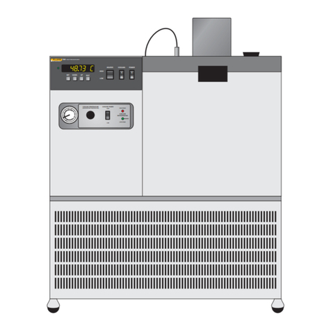
Fluke TS 30 User manual

TS®30
Test Set
PN 2448469
October 2005 Rev. 1 10/08
©2005, 2008 Fluke Corporation. All rights reserved. Printed in China.
All product names are trademarks of their respective companies.
Users Guide

LIMITED WARRANTY AND LIMITATION OF LIABILITY
Each Fluke Networks product is warranted to be free from defects in material and workmanship under
normal use and service. The warranty period for the mainframe is 18 months and begins on the date of
purchase. Parts, accessories, product repairs and services are warranted for 90 days, unless otherwise stated.
Ni-Cad, Ni-MH and Li-Ion batteries, cables or other peripherals are all considered parts or accessories. The
warranty extends only to the original buyer or end user customer of a Fluke Networks authorized reseller,
and does not apply to any product which, in Fluke Networks’ opinion, has been misused, abused, altered,
neglected, contaminated, or damaged by accident or abnormal conditions of operation or handling. Fluke
Networks warrants that software will operate substantially in accordance with its functional specifications
for 90 days and that it has been properly recorded on non-defective media. Fluke Networks does not warrant
that software will be error free or operate without interruption.
Fluke Networks authorized resellers shall extend this warranty on new and unused products to end-user
customers only but have no authority to extend a greater or different warranty on behalf of Fluke Networks.
Warranty support is available only if product is purchased through a Fluke Networks authorized sales outlet
or Buyer has paid the applicable international price. Fluke Networks reserves the right to invoice Buyer for
importation costs of repair/replacement parts when product purchased in one country is submitted for repair
in another country.
Fluke Networks warranty obligation is limited, at Fluke Networks option, to refund of the purchase price,
free of charge repair, or replacement of a defective product which is returned to a Fluke Networks
authorized service center within the warranty period.
To obtain warranty service, contact your nearest Fluke Networks authorized service center to obtain return
authorization information, then send the product to that service center, with a description of the difficulty,
postage and insurance prepaid (FOB destination). Fluke Networks assumes no risk for damage in transit.
Following warranty repair, the product will be returned to Buyer, transportation prepaid (FOB destination).
If Fluke Networks determines that failure was caused by neglect, misuse, contamination, alteration, accident
or abnormal condition of operation or handling, or normal wear and tear of mechanical components, Fluke
Networks will provide an estimate of repair costs and obtain authorization before commencing the work.
Following repair, the product will be returned to the Buyer transportation prepaid and the Buyer will be
billed for the repair and return transportation charges (FOB Shipping point).
THIS WARRANTY IS BUYER’S SOLE AND EXCLUSIVE REMEDY AND IS IN LIEU OF ALL OTHER WARRANTIES,
EXPRESS OR IMPLIED, INCLUDING BUT NOT LIMITED TO ANY IMPLIED WARRANTY OR MERCHANTABILITY OR
FITNESS FOR A PARTICULAR PURPOSE. FLUKE NETWORKS SHALL NOT BE LIABLE FOR ANY SPECIAL, INDIRECT,
INCIDENTAL OR CONSEQUENTIAL DAMAGES OR LOSSES, INCLUDING LOSS OF DATA, ARISING FROM ANY
CAUSE OR THEORY.
Since some countries or states do not allow limitation of the term of an implied warranty, or exclusion or
limitation of incidental or consequential damages, the limitations and exclusions of this warranty may not
apply to every buyer. If any provision of this Warranty is held invalid or unenforceable by a court or other
decision-maker of competent jurisdiction, such holding will not affect the validity or enforceability of any
other provision.
4/04-18
Fluke Networks
PO Box 777
Everett, WA 98206-0777
USA

i
Table of Contents
Title Page
Overview of Features ........................................................................................................................................1
Registration .......................................................................................................................................................1
Contacting Fluke Networks ..............................................................................................................................1
Safety Information ............................................................................................................................................2
Physical Characteristics .....................................................................................................................................2
Mode Controls ...........................................................................................................................................2
Keypad ........................................................................................................................................................3
Dialing Keys ................................................................................................................................................3
Light Emitting Diodes (LEDs) .....................................................................................................................3
Line Cord ...........................................................................................................................................................4
Operation ..........................................................................................................................................................4
Line Monitoring .........................................................................................................................................4
Dialing ........................................................................................................................................................4
Flash ............................................................................................................................................................4
Mixed Mode Dialing ..................................................................................................................................4
Last Number Redial ....................................................................................................................................5
Polarity Check ............................................................................................................................................5
Transmitter Mute .......................................................................................................................................5
Receiving Calls ............................................................................................................................................5
Maintenance .....................................................................................................................................................5
Belt Clip Replacement ...............................................................................................................................5
Line Cord Replacement .............................................................................................................................6
Accessories ..................................................................................................................................................6
Specifications .....................................................................................................................................................7

TS30 Test Set
Users Guide
ii

1
TS®30 Test Set
Overview of Features
The TS30 Test Set is a portable handset used by
installers, repair technicians and other authorized
personnel for testing of telephone lines and for
temporary communications. The TS30 is powered by
the telephone line. It does not require any batteries.
The following is a list of the TS30 features:
•
Talk and Monitor modes
•
Tone and Pulse dial signaling
•
Transmitter mute
•
Last Number Redial in Tone and Pulse Modes
•
Automatic regulation of speech levels
•
Hearing aid compatible receiver
•
Hook flash generation
•
Line polarity indicators
•
Fully functional with either line polarity
•
High impedance Monitor mode
•
Electronic ringer
•
Overvoltage protection
•
Impact resistant and rain resistant
•
Field replaceable line cord
•
Field replaceable spring-loaded belt clip
•
Ergonomic design
Registration
Registering your product with Fluke Networks gives
you access to valuable information on product updates,
troubleshooting tips, and other support services. To
register, fill out the online registration form on the
Fluke Networks website at www.flukenetworks.com/
registration.
Contacting Fluke Networks
www.flukenetworks.com
+1-425-446-4519
•
Australia: 61 (2) 8850-3333 or 61 3 9329 0244
•
Beijing: 86 (10) 6512-3435
•
Brazil: 11 3759 7600
•
Canada: 1-800-363-5853
•
Europe: +44-(0)1923-281-300
•
Hong Kong: 852 2721-3228
•
Japan: 03-3434-0510
•
Korea: 82 2 539-6311
•
Singapore: 65-6799-5566
•
Taiwan: (886) 2-227-83199
•
USA: 1-800-283-5853
•
Anywhere in the world: +1-425-446-4519
Visit our website for a complete list of phone numbers.

2
TS30 Test Set
Users Guide
Safety Information
The following IEC symbols are used either on the test
set or in the manual:
WXWarning
Do not use the test set if it is damaged.
Before you use the test set, inspect the case.
Look for cracks or missing plastic. Pay
particular attention to the insulation
surrounding the connectors.
If this product is used in a manner not
specified by the manufacturer, the
protection provided by the product may be
impaired.
Physical Characteristics
See Figure 1.
The TS30 housing is made of high-impact plastic. The
unit provides rugged service and withstands the rough
handling and shocks normally associated with field use.
The TS30 housing permits operation in bad weather,
such as in rain and dust storms.
The back of the handgrip has a contoured surface,
which lets you grip the test set between chin and
shoulder, leaving both hands free for other tasks.
The keypad has 16 keys that are recessed. The recessed
area protects the keypad and reduces accidental
pressing of the keys.
The belt clip includes a spring-loaded clip that ensures a
secure connection to belt loops and D-rings.
bfl01.eps
Figure 1. Physical Characteristics
The line cord is attached through a rubber strain relief.
See “Line Cord”.
The electronic ringer is located near the belt clip on the
hand grip.
Mode Controls
See Figure 2.
The TALK/MONITOR switch is on the inside of the hand
grip near the transmitter. It puts the unit on-hook
(Monitor mode) or off-hook (Talk mode).
WWarning: Risk of personal injury. See the
manual for details.
Caution: Risk of damage or destruction to
equipment or software. See the manual for
details.
XWarning: Risk of electric shock.
.Earth ground
PConformité Européenne. Conforms to
relevant European Union directives.
)CAN/CSA-C22.2 No. 60950-1-03
CAN/CSA-C22.2 No. 1010.1-92 + CSA-C22.2
No. 1010.1B-97, UL/ANSI 3111-1
~Do not put products containing circuit
boards into the garbage. Dispose of circuits
boards in accordance with local
regulations.

3
Physical Characteristics
The TONE/PULSE switch is on the inside of the hand
grip near the receiver. This switch selects the dialing
mode.
bfl02.eps
Figure 2. Controls and Indicators
Keypad
See Figure 3.
The TS30 Test Set keypad includes 12 standard dialing
keys and 4 special purpose keys. All keys on the keypad
are functional when the unit is in the Talk mode. They
are not functional when the unit is in the Monitor
mode.
bfl03.eps
Figure 3. Keypad
MUTE: Pressing the MUTE key shuts off the TS30
transmitter for as long as the key remains depressed.
POLAR: When an off-hook unit is connected to a
powered telephone line, pressing the POLAR key
causes one of the LEDs to turn on. The LEDs indicate
the polarity of direct current on the telephone line.
FLASH: Pressing the FLASH key will cause a timed
interruption of the loop current. Some PBX setups or
telephone office switches may use this signal to put a
call on hold or to activate some special function.
REDIAL: This key allows the user to redial the last
number dialed.
Dialing Keys
See Figure 3.
When the TONE/PULSE switch is in the TONE position,
each of the 12 dialing keys, when pressed, generate
dialing tones. This includes the asterisk (∗) and the
pound (#) keys. When the TONE/PULSE switch is in the
PULSE position, only the numeric keys (1, 2, 3, 4, 5, 6, 7,
8, 9, 0) will cause pulses to be generated when pressed.
In Pulse mode, the asterisk and pound keys are not
functional. In Pulse mode the asterisk and pound keys
will not be stored in the redial memory.
The special purpose keys are labeled MUTE, POLAR,
FLASH, and REDIAL.
Light Emitting Diodes (LEDs)
See Figure 3.
The LEDs are on each side of the keypad. One or the
other of the LEDs will light only when the test set is in
the Talk mode, connected to a powered telephone
line, and the POLAR key is pressed. The LEDs indicate
the polarity of current on the transmission line. See
“Polarity Check”.

4
TS30 Test Set
Users Guide
Line Cord
See Figure 4.
The TS30 comes with a line cord for connecting the test
set to telephone lines. This line cord consists of one red
and one black insulated conductor, each approximately
1.5 meters long. Each clip is covered with a neoprene
boot to prevent the clips from causing electrical shorts.
bfl04.eps
Figure 4. Line Cord with ABN Clips
Operation
WWarning
When connecting to metallic network wires,
handle alligator clips by insulated boots.
Line Monitoring
Move the TALK/MONITOR switch to MONITOR and
connect the red and black test leads to the telephone
line wire pair under test. If there is any audio on the
line under test, it can now be heard in the unit’s
receiver. Because the TS30 presents a high impedance
to the line when in Monitor mode, it will not disturb
existing signals on the line under test. Monitor mode is
typically used by service personnel to verify that there is
no call in progress on the wire pair before going off-
hook.
Dialing
Note
If tone dialing is selected, the tones associated
with each digit will be generated as its
respective key is pressed. If pulse signaling has
been selected, the desired number may be
entered at any rate on the keypad. The digits
will automatically be pulsed out at the correct
rate.
Move the TALK/MONITOR switch to the MONITOR
position and connect the red and black test leads to the
wire pair under test. Move the TONE/PULSE switch to
select the desired dialing mode. Move the TALK/
MONITOR switch to TALK, and verify that dial tone is
received. Enter the number to be called on the keypad.
To end the call, either during or after dialing, move the
TALK/MONITOR switch to the MONITOR position.
Flash
Some telephone services require a timed hook flash
(approximately ½ second on-hook/off-hook loop
interruption) to activate features. The FLASH key
provides this timed hook flash signal.
Mixed Mode Dialing
On some telephone lines, calls can only be set up by
pulse dialing. Once the call is established in Pulse mode,
then the TONE/PULSE switch can be moved to the
TONE position. Tones can now be sent over the
telephone lines by pressing dialing keys. This is useful
when there is a need to send dialing tones as data to
activate some function in a device connected to the
other end of the telephone line. For example, dialing
tones can be used to command an answering machine
to play back recorded messages.

5
Maintenance
Last Number Redial
If a call is not successful and you wish to redial that
number, do the following: Put the TS30 Test Set into
Monitor mode, then put the unit back into Talk mode,
and press the REDIAL key. The last number dialed will
be automatically redialed. The number in the redial
memory is saved for about 8 minutes when the unit is
in Monitor mode. The last number redial function is
available in either the Pulse or Tone mode. The redial
memory has a 23-digit capacity.
Polarity Check
Connect the TS30 Test Set to a powered wire pair.
Move the TALK/MONITOR switch to TALK and press the
POLAR key. The green LED will light if the red test lead
is connected to a more negative voltage than the black
test lead. The red LED will light if the red test lead is
connected to a more positive voltage than the black
lead.
Transmitter Mute
When using the TS30 Test Set in a noisy environment,
such as near a street with a lot of automobile traffic,
the ambient noise will enter the TS30 Test Set’s
transmitter and a portion of the noise will be sent to
the receiver (side tone effect). This noise may be loud
enough in the receiver to make it difficult to hear the
person on the other end of the telephone line. Press
and hold the MUTE key to shut off the transmitter, thus
eliminating the ambient noise and making it easier to
hear the person at the other end of the telephone line.
Receiving Calls
To receive an incoming call, put the TALK/MONITOR
switch in the MONITOR position. Incoming call signals
on the telephone line will cause the TS30 to produce a
ringing sound. To answer the incoming call, move the
TALK/MONITOR switch to the TALK position.
Maintenance
WCaution
Disconnect from telephone network when
replacing line cord.
Do not use CRC Cable Clean®or any similar
chlorinated solvent on the TS30 Test Set.
Doing so will damage the test set.
Belt Clip Replacement
See Figure 5.
The TS30 belt clip can be replaced by the user if it
becomes damaged or wears out. To obtain a
replacement belt clip contact your local distributor or
Fluke Networks.
To replace the belt clip assembly:
1
Using a Phillips screwdriver, remove the two screws
that secure the belt clip to the test set housing.
2
Remove the old belt clip and replace with a new
one.
3
Secure the belt clip assembly to the test set
housing with the original screws. Be careful not to
over tighten the screws.
bfl05.eps
Figure 5. Replacing the Belt Clip

6
TS30 Test Set
Users Guide
Line Cord Replacement
The line cord can be replaced by the user. To replace
the line cord refer to the instructions that come with
the replacement line cord. To obtain a replacement line
cord contact your local distributor or Fluke Networks.
Accessories
To order accessories, contact your local distributor or
Fluke Networks.
Description
Fluke Networks
Model Number
Angled Bed-of-Nails Cord (ABN) P3080009
Load Coil Standard Line Cord
(STD) with Piercing Pin Clips
P3080001
Belt Clip P3218350

7
Specifications
Specifications
Electrical
Return Loss >14 dB (ref 600 Ω)
Line Current Range 15 mA to 120 mA
Resistance to
Continuous Current
(Talk Mode)
275 Ω typical at 20 mA
Monitor Mode
Impedance
>120,000 Ω
300 Hz to 3400 Hz
Pulse Dial Output
Pulsing Rate 10 pps +1 pps
Open/Close Ratio 60/40
Inter-digit Interval 800 ms +20 %, -10 %
Resistance During
Pulse Open
> 200,000 Ω
Protection Against
Alternating Current
Overvoltage
The TS30 survives up to
250 Vrms across its test
leads.
Peak Acoustic Output
of the Receiver
<120 dBspl
DTMF Output
Tone Frequencies
Tone Frequency Error
per ITU-T Q.23
±1.5% maximum
Tone Level
High Group
Low Group
-4 dBm +2 dB (into 600 Ω)
-6 dBm +2 dB (into 600 Ω)
High vs Low Tone
Difference
2dB +1db
Last Number Redial (Tone/Pulse)
Memory Capacity
Memory Retention
23 digits
8-minutes nominal
Flash Duration 600 ms ±100 ms
Ringer Loudness > 70 dBA at 1 meter
Ringer Equivalent (REN) 0.14
Physical
Measurements 10 in x 2.83 in x 3.34 in
(25.5 cm x 7.2 cm x 8.5 cm)
Weight 16.8 ounces (0.476 kg)
Environmental
Temperature
Operating -4 °F to +140 °F
(-20 °C to +60 °C)
Storage -40 °F to +151 °F
(-40 °C to +66 °C)
Altitude To 3,000 m (10,000 ft)
maximum
Relative Humidity 5 % to 95 %
(non-condensing)
Safety
Telecom Electrical
Safety Classification
TNV-3
IP54
Regulatory Standards Used
47 CFR Part 15, Subpart B
ICES-003 Issue 3
AS/NZS 3548
EMC Directive 89/336/EEC, EN 55022:98,
EN 61326:97, A1:98 Annex C, EN 61000-4-2,
EN 61000-4-3
LV Directive 73/23/EEC, EN 610010.1 (1993)
Certifications and Compliance
Conformité Européenne. Conforms to
relevant European Union directives.
CAN/CSA-C22.2 No. 60950-1-03
CAN/CSA-C22.2 No. 1010.1-92 + CSA-C22.2
No. 1010.1B-97, UL/ANSI 3111-1
Notes
Specifications subject to change without notice.
Legal requirements may exist regarding permission
to connect equipment to a Telecom network
operated by a public network operator.

8
TS30 Test Set
Users Guide
Table of contents
Other Fluke Test Equipment manuals

Fluke
Fluke 5320A User manual

Fluke
Fluke 165X User manual

Fluke
Fluke 729 User manual

Fluke
Fluke 5440B/AF User manual

Fluke
Fluke VisiFault Visual Fault Locator User manual

Fluke
Fluke 154 HART User manual

Fluke
Fluke 5700A Series II Service User manual

Fluke
Fluke HART 744 User manual

Fluke
Fluke NetDAQ 2640A User manual

Fluke
Fluke 5080A User manual

Fluke
Fluke CombiScope PM3370B User manual

Fluke
Fluke CableIQ User manual

Fluke
Fluke 71 Series Use and care manual

Fluke
Fluke DTX-MFM User manual

Fluke
Fluke 9009 User manual

Fluke
Fluke Fiber Viewer FT120 User manual

Fluke
Fluke 9640A Series User manual

Fluke
Fluke 4180ETRS User manual

Fluke
Fluke 715 User manual

Fluke
Fluke 707Ex User manual