FMS EMGZ309 User manual

Operating Manual
EMGZ309
Digital Microprocessor Controlled Tension Amplifier
Version 2.12 08/2017 NS
Firmware Version V2.10
Diese Bedienungsanleitung ist auch in Deutsch erhältlich.
Bitte kontaktieren Sie Ihren nächstgelegen FMS Vertreter.
© by FMS Force Measuring Systems AG, CH-8154 Oberglatt – All rights reserved.

Operation Manual EMGZ309
07.08.2017 2
Table of contents
1 Safety Instructions ..................................................................................... 3
1.1 Description conditions 3
1.2 List of safety instructions 3
2 System Description ................................................................................... 4
2.1 Functional description 4
2.2 Block Diagram 4
3 Quick Installation Guide ............................................................................ 5
3.1 Preparations for Set-up 5
3.2 Installation Procedure 5
3.3 Installation and wiring 5
3.4 Mounting the Force Sensors 6
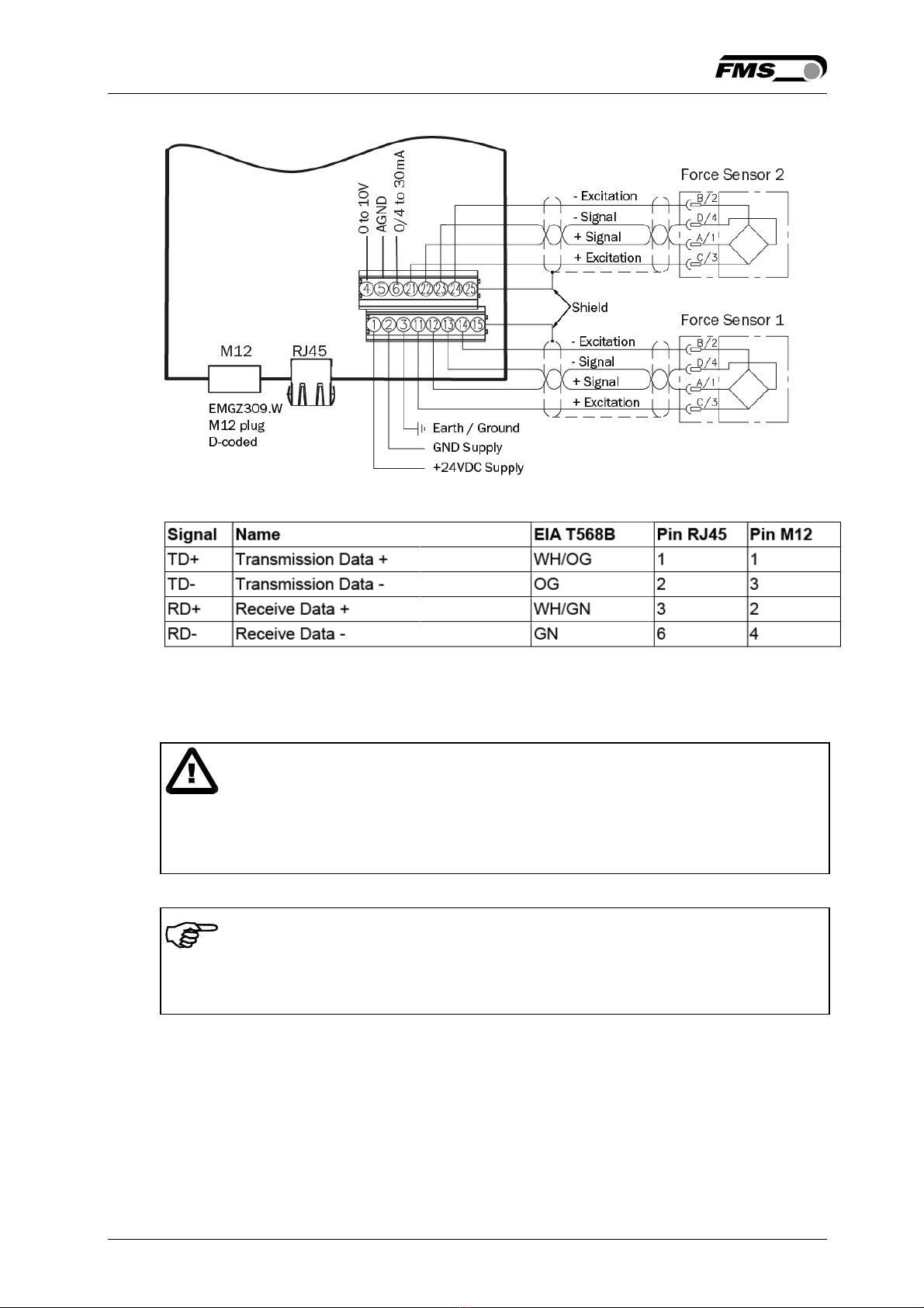
3.5 Wiring the Amplifier 6
4 Configuring the Amplifier ......................................................................... 8
4.1 Power up the EMGZ 309 8
4.2 Operating Panel 8
4.3 Change the Measuring Units 9
4.4 Change the Device Mode 9
4.5 Offset Compensation 9
4.6 Offset Compensation over the Operating Panel 10
4.7 Calibration 10
4.8 Calibration over the Operating Panel 11
4.9 Analytic Calibration Method) 12
5 Operation .................................................................................................. 14
5.1 Operating the EMGZ309 over the Operating Panel 14
5.2 Display Value Selection State 15
5.3 Displaying of Overload, Over and Underflow 15
6 Parameterization over the Operating Panel ......................................... 16
6.1 Reset to Default Parameter Set 18
6.2 Parameter List 19
6.3 Description of Parameters 20
7 Parameter Setting via a PC .................................................................... 25
7.1 Parameterization in an Ethernet Network via Web Browser 26
7.2 Offset Compensation via the Web Browser 30
7.3 Calibration via the Web Browser 30
7.4 Connecting the EMGZ309 Amplifier with a PC (Peer-to-Peer) 32
8 Dimensions .............................................................................................. 35
9 Technical Specification ........................................................................... 37

Operation Manual EMGZ 309
07.08.2017 3
1 Safety Instructions
1.1 Description conditions
a) High danger of health injury or loss of life
Danger
This symbol refers to high risk for persons to get health injury or loss of life. It has
to be followed strictly.
b) Risk of damage of machines
Caution
This symbol refers to informations, that, if ignored, could cause heavy mecanical
damage. This warning has to be followed absolutely.
c) Note for proper function
Note
This symbol refers to an important information about proper use. If not followed,
malfunction can be the result.
1.2 List of safety instructions
Proper function of the Tension Measuring Amplifier is only guaranteed with the
recommended application of the components. In case of other arrangement,
heavy malfunction can be the result. Therefore, the installation instructions on
the following pages must be followed strictly.
Local installation regulations are to preserve safety of electric equipment. They
are not taken into consideration by this operating manual. However, they have to
be followed strictly.
Bad earth connection may cause electric shock to persons, malfunction of the
total system or damage of the electronic unit! It is vital to ensure that proper
earth connection is done.
Improper handling of the electronic boards may cause damage to the fragile
equipment! Don’t use rough tools such as screwdrivers or pliers! Operators
handling the electronic boards must wear a well earthed bracelet in order to
discharge static electricity.

Operation Manual EMGZ309
07.08.2017 4
2 System Description
Fig. 1: System Configuration EMGZ309 Tension Measuring Amplifier E309012e
2.1 Functional description
The digital tension measuring amplifiers EMGZ309 are suitable for tension
measurement with all FMS force sensors. This versatile product comes as a plug &
play unit and is very easy to setup through the operating panel. Alternatively, more
advanced users can access all the internal parameters through a Web Browser
and set up the device over a PC. The amplifier is then either connected to a
network (e.i. Ethernet) or via a peer-to-peer configuration to a laptop or local PC. A
wealth of options allows the optimization of the amplifier to almost any
application.
2.2 Block Diagram
Fig. 2: Block diagram EMGZ309 Tension Measuring Amplifier E309011e

Operation Manual EMGZ 309
07.08.2017 5
3 Quick Installation Guide
In a Plug & Play configuration the set-up of the EMGZ309 and force sensor is
limited to only the offset compensation and the calibration.
3.1 Preparations for Set-up
1. Read the Operation Manual of your force measuring sensors
2. Check your requirements such as:
– Desired output configuration 0…10V or 0/4… 20mA
– Display unit of nominal force
3. Draw the wiring diagram for your configuration (ref. to 3.5 “Wiring the
Amplifier“)
4. If required, determine special parameters (ref. to 6“Parameterization over
Operating Panel”)
3.2 Installation Procedure
1. Mount your force maesuring sensors to the machine frame (ref. to paragraph
3.4)
2. Wire the Force Measuring Sensor(s) (ref. to Fig. 3)
3. Connect the amplifier to the power supply.
4. The power supply voltage must be in the range 18 to 36V DC.
5. Perform offset compensation and calibration (ref. to chapters 4.5 to 4.9)
6. If required, do additional settings (ref. to 6“ Parameterization over Operating
Panel”)
3.3 Installation and wiring
Caution
In order to improve the natural convection and keep the temperature of the
amplifiers that are mounted in a cabinet, to a minimum, a distance of at least
15mm (0.6”) between the devices must be kept.
Caution
Proper function of the Tension Measuring Amplifier is only guaranteed with the
recommended application of the components. In case of other arrangement,
heavy malfunction can be the result. Therefore, the installation instructions on the
following pages must be followed strictly.

Operation Manual EMGZ309
07.08.2017 6
Caution
Local installation regulations are to preserve safety of electric equipment. They
are not taken into consideration by this operating manual. However, they have to
be followed strictly.
3.4 Mounting the Force Sensors
Mounting of the force sensors is done according to the FMS Installation manual
which is delivered together with the force sensors.
3.5 Wiring the Amplifier
One or two force sensors can be connected to the measuring amplifier. When
using two force sensors, the sensors are internally connected in parallel. The
output signal of the measuring amplifier will then correspond to the average value
of the two sensors.
The connection between force sensors and measuring amplifier has to be done
using a 2x2x0.25mm2[AWG 23] shielded twisted-pair cable. The cable must be
installed separate from power lines.

Operation Manual EMGZ 309
07.08.2017 7
Fig. 3: Wiring Diagram EMGZ309 EMGZ_309_BA_Manual.ai
Ethernet connectors EMGZ_309_BA_Manual.ai
Caution
Bad earth ground connection may cause electric shock to persons, malfunction of
the total system or damage of the electronic unit! It is vital to ensure that proper
earth connection is done.
Note
The shield should be connected only to the electronic unit. On the force sensor
side the shield should stay open.

Operation Manual EMGZ309
07.08.2017 8
4 Configuring the Amplifier
4.1 Power up the EMGZ 309
1. Connect the first force sensor (see Fig.3 Wiring Diagram EMGZ309)
2. Check whether applying a force in measuring direction (in the direction of the
red point) on the first sensor results in a positive output signal. If not, exchange
the two signal wires of the corresponding force sensor in the terminal block
(terminals 12/13).
3. If applicable, connect the second force sensor.
4. Check whether applying a force in measuring direction on the second sensor
results in a positive output signal. If not, exchange the two signal wires of the
corresponding force sensor in the terminal block (terminals 22/23)
4.2 Operating Panel
Fig. 4: Operating Panel EMGZ309.W E309007e
The keys on the operating panel have the following functions:
Key Key Function
Change the selections or increase / decrease the values
Enter
>0< + PARA Enter Offset Compensation Procedure. Press the two keys at
the same time for longer then 3 sec.
Cal + PARA Enter Calibration Procedure. Press the two keys at the same
time for longer then 3 sec.
PARA Enter the Parameter Setting Mode. Press the key at the same
time for longer then 3 sec.

Operation Manual EMGZ 309
07.08.2017 9
4.3 Change the Measuring Units
The default tension measuring units is N (Newton). The user can, however, select
another unit before the calibration process. To select the units of measure, follow
the steps below:
1. Hold the PARA key until the display changes to [Dis. Filt]
2. Scroll the menu by pressing the key until the display shows [Unit]
3. Press the and the word [Unit] will start flashing indicating that the unit of
measure can now be changed.
4. With every press of the keys the display will change from N, kN, then
to lb, g, kg.
5. Stop at the desired unit and press the again to confirm the selection.
6. Press the PARA key for longer then 3 sec. to save the setting and return to the
Operating State. Or if no action is taken after 30 seconds, the value will be
stored in the system automatically.
4.4 Change the Device Mode
The EMGZ309 amplifiers have two Device Modes:
● Display of Force Gauge: Tension data are displayed in a force unit
● Display of Voltage Gauge: Tension data are displayed in Volt (V)
1. Go to Parameter Selection Mode (press PARA key longer than 3 sec).
2. Go to Parameter [DevicMod]
3. With the key select desired Device Mode [ForcGaug] or [VoltGaug] and
confirm selection with the key .
Note
Each change of the Device Mode requires a re-calibration of the system (see
chapter 4.8).
4.5 Offset Compensation
With the Offset Compensation you can compensate the roller weight. It is always
performed before the calibration. The Force Measuring Sensor should not be
loaded while the Offset Compensation is being done. There are two possible ways
performing the offset compensation.
A) Offset compensation over the operating panel (see chapter 4.6)
B) Offset compensation via the Web Browser.
For this method proceed to chapter 7.2; Fig. 22 and 23.

Operation Manual EMGZ309
07.08.2017 10
4.6 Offset Compensation over the Operating Panel
1. Press the two keys >0< and PARA at the same time for longer then 3 seconds.
2. The display will show [Offset Complete] when the process is finished (see Fig. 5
State diagram offset compensation).
Fig. 5: State diagram offset compensation EMGZ309013e
4.7 Calibration
By calibrating (setting the Gain), amplifier and
load cells are adjust so that the display gives the
actual tension value. There are two methods of
calibrating the system. The first method uses a
defined weight (see Fig. 6). This method is the
preferred one since it delivers the most accurate
results. The second method is based on a
calculation method in conjunction with the FMS
Calculator. This Calculator can be down loaded
from the FMS web page. Please consult the
factory for this option.
The calibration can be performed over the
Operation Panel or via the Web Browser. For the
later proceed to chapter 7.3, Fig. 22 and 23.
Note
If the Device Mode is set to [VoltGaug], the force corresponding to the calibration
weight must be input in Volt (V) in the following calibration procedure. The
parameters System Force [SysForce] and Force at maximum output [F@OutMax]
won’t be requested (see also chapter 7.3, section B).
Fig. 6: Calibrating the
measuring amplifier
C431011e

Operation Manual EMGZ 309
07.08.2017 11
4.8 Calibration over the Operating Panel
1. Load a rope with a defined weight corresponding to your calibration force on
the roller. The roller configuration must correspond to the real configuration in
the machine (wrap angle, distance of the rollers etc.).
2. Enter calibration mode by pressing the two keys Cal and PARA at the same
time for longer than 3 seconds. The display changes to
3. The System Force [SysForce] determines the measuring
capability of your measuring roller. E.g. if two 500 N sensors are installed,
enter 1000N. If only one 500N sensor is used, enter 500N (see 6.2 and 6.3
“Descriptions of Parameter”, [SysForce]).
4. The parameter [SysForce] flashes indicating that the force can now be
changed. Use keys to enter the system force.
5. Press the key to confirm your input. The display changes to
6. Enter the force corresponding to your calibration weight with the
7. Press the key to confirm your input. The display changes to
8. The parameter [F@OutMax] determines the force corresponding to the
maximum amplifier output (10V or 20mA) (see 6.3 “Descriptions of
Parameter”, [F@MaxOut]). Enter the value with the keys.
9. Press the key to confirm your input. The display changes to
The calibration procedure has been completed successfully.
Fig. 7: State diagram calibration EMGZ309014e
1) The display shows the unit of measure that was previously selected.
3) Permanent key pressing expedites the changing speed.
4) If the Device Mode [VoltGauge] is set, these parameters are deactivated
SysForce
1000.0 N
Calibra.
1000.0 N
F@OutMax
1000.0 N
Calibra.
Com
p
lete

Operation Manual EMGZ309
07.08.2017 12
4.9 Analytic Calibration Method)
Determining the gain by means of the FMS-Calculator:
This method is used when the traditional calibration method with a weight is
difficult or impossible at all due to machine accessibility, weight adequateness etc.
This calculation method requires the FMS-calculator V2.1 or higher.
If necessary download and install FMS-calculator from the FMS homepage at:
http://www.fms-technology.com/en/technical-information.php
Gain-calculation-tool
The gain calculator is an optional feature of the FMS-calculator. It delivers the gain
factor for easy weightless calibration of FMS amplifiers.
1. First, the application related parameters must be entered in the FMS-calculator
e.g. min./max. force values, wrap angle and other sensor specifications. Follow
the instructions of the FMS-calculator manual.
2. Choose the appropriate sensor type.
3. If the sensor evaluation is correct, the gain calculation tool can be started with
a click on the corresponding symbol.
4. The data will be taken over from the previous input (field (1) Fig. 8). The gain
calculation tool will only start-up, if all data have been entered and the
appropriate sensor defined.
5. Choose the amplifier type (field (2) Fig. 8).
6. The calculated gain factor is available in the field (3) (see Fig. 8)
Calibration Procedure:
1. Calculate the gain factor with the FMS-calculator as described (see above).
2. Press the PARA key for longer than 3 seconds to entered the parametrisation
mode.
3. Scroll up or down the parameter menu with the keys until the display
show [Gain].
4. Confirm the parameter with the key
5. The display will start flashing indicating that the gain factor can now be
entered.
6. Use the keys to enter the calculated value.
7. Press the key to confirm the input. Or if no action is taken after 30 seconds,
the value will be stored in the system automatically.

Operation Manual EMGZ 309
07.08.2017 13
Fig. 8: Gain calculation tool E309_gain_e.jpg
1
2
3

Operation Manual EMGZ309
07.08.2017 14
5 Operation
5.1 Operating the EMGZ309 over the Operating Panel
The EMGZ309 amplifier can go in 5 different states:
• Operation State: Amplifier operating
• Display Selection: Selection of force or output reading
• Offset Compensation: Automatic procedure to offset the roller weight
• Calibration State: Procedure to calculate the amplifier gain
• Parameterisation State: Set or change parameters
When using the front panel, the user can toggle between these modes by pressing
a key or a combination of keys. Fig. 9 provides an overview about the different
Operation States and how to move from one state to the other.
Fig. 9: Top-level view of operation control E309015e
1) The display shows the unit of measure that was previously selected.

Operation Manual EMGZ 309
07.08.2017 15
5.2 Display Value Selection State
The EMGZ309 can display either a tension value or the amplifier output that is an
electrical unit corresponding to the measured tension.
A) For tension display following unit can be selected: N, kN, lb, g, kg
B) The amplifier output can be displayed in 0…10VDC, 0…20mA or 4…20mA
5.3 Displaying of Overload, Over and Underflow
In the Operation State the EMGZ309 amplifier will indicate limit violations on the
display depending on the chosen unit:
A) If a tension has been chosen, the reading on the display at overload will be:
B) If the display was set to show the amplifier output, following messages will be
displayed:
At overflow: or
At underflow: or
Note
An overflow messages is caused by the maximum output value 10V or 20mA
being overshot. An underflow message is caused by the minimum value 0V or
4mA being undershot. The parameter [F@OutMax] can influence the overflow
messages. If the actual tension value overflows the value entered in [F@OutMax],
an error message will be displayed.
Overload
1200.0 N
Out>Max
20.00 mA
Out<Min
0.00
Out>Max
10.00V
Out<Min
0.00 V

Operation Manual EMGZ309
07.08.2017 16
6 Parameterization over the Operating Panel
After offset compensation and calibration the system is configured. It can now be
put into operation. The following state diagrams (Fig. 10 -12) help to navigate
through the parameter setting menu. In the Parameterisation State the EMGZ309
can be brought into the 2 modes: “Parameter Selection” and “Parameter Change”.
Fig. 10: State Diagram Parameter Setting (1st part) E309016e

Operation Manual EMGZ 309
07.08.2017 17
1) The display shows the unit of measure that was previously selected.
3) Permanent key pressing expedites the changing speed.
4) If the Device Mode [VoltGauge] is set, these parameters are deactivated
Fig. 11: State Diagram Parameter Setting (2nd part) E309017e

Operation Manual EMGZ309
07.08.2017 18
Fig. 12: State Diagram Parameter Setting (3rd part) E309018e
6.1 Reset to Default Parameter Set
Factory settings can be re-established either over the parameter setting menu (see
6.3 “Description of Parameters”) or as shown in the state diagram below:
Fig. 13: Reset to Default Parameter Set E309027e

Operation Manual EMGZ 309
07.08.2017 19
6.2 Parameter List
Parameter Unit Min Max Default Remarks
Dis Filt. [Hz] 0.1 10.0 1.0
Out Filt. [Hz] 0.1 200.0 10.0
Unit 4) [-] N, kN, lb, g, kg. N
SysForce 4) [N] 1) 1 100’000 1000
F@OutMax 4) [N] 1) 1 100’000 1000
Curr.Out mA 0...20 or 4...20 4…20
Offset [Digit] –8000 8000 0
Gain [-] 0.100 20.000 1.000
DevicMod [-] ForcGaug or VoltGaug ForcGaug Each
parameter
change
requires re-
calibration
Language [-] English or German English
Contrast [%] 1 100 65 .
Ethernet [-] On or Off On If Off, reduces
power
consumpt
IP Addr. [-] 0 255 192
168
0
090
Address to be
entered in 4
blocks
Subnet [-] 0 255 255
255
255
0
Address to be
entered in 4
blocks
LANSpeed MBPS 10 100 100
Default [-] No, Yes Yes
1) The display shows the unit of measure that was previously selected.
4) If the Device Mode [VoltGauge] is set, these parameters are deactivated

Operation Manual EMGZ309
07.08.2017 20
6.3 Description of Parameters
Display Filter LCD: Dis.Filt
Use: The controller provides a low-pass filter to prevent noise overlaying the
output signal. The parameter Dis.Filt stores the cut off frequency of
the filter. The lower the cut off frequency, the more sluggish the
display will be. A correctly tuned filter will steady the value shown in
the display. The display filter does not influence the output signal filter
described below (parameter Out.Filt).
Unit Parameter Range Selection Default
Min Max
Hz 0.1 10.0 - 1.0
Filter Amplifier Output LCD: Out.Filt
Use: The EMGZ309 contains a lowpass filter to prevent noise overlaying to
the output signal. This parameter stores the cut off frequency of the
filter. The lower the cut off frequency, the more sluggish the output
signal will be. The filter stabilizes the output signal in case of highly
fluctuating force values. This filter is independent from the display
filter (see obove).
Unit Parameter Range Selection Default
Min Max
Hz 0.1 200.0 - 10.0
Unit of Measure LCD: Unit
Use: This parameter determines the unit used in the system.
By changing the units to lb (pounds) the whole unit system will change
from metric to imperial units.
If the Device Mode [VoltGauge] is set, this parameter is deactivated
Unit Parameter Range Selection Default
Min Max
- - -
N
kN
lb
g
kg
N
Other manuals for EMGZ309
1
Table of contents
Other FMS Amplifier manuals