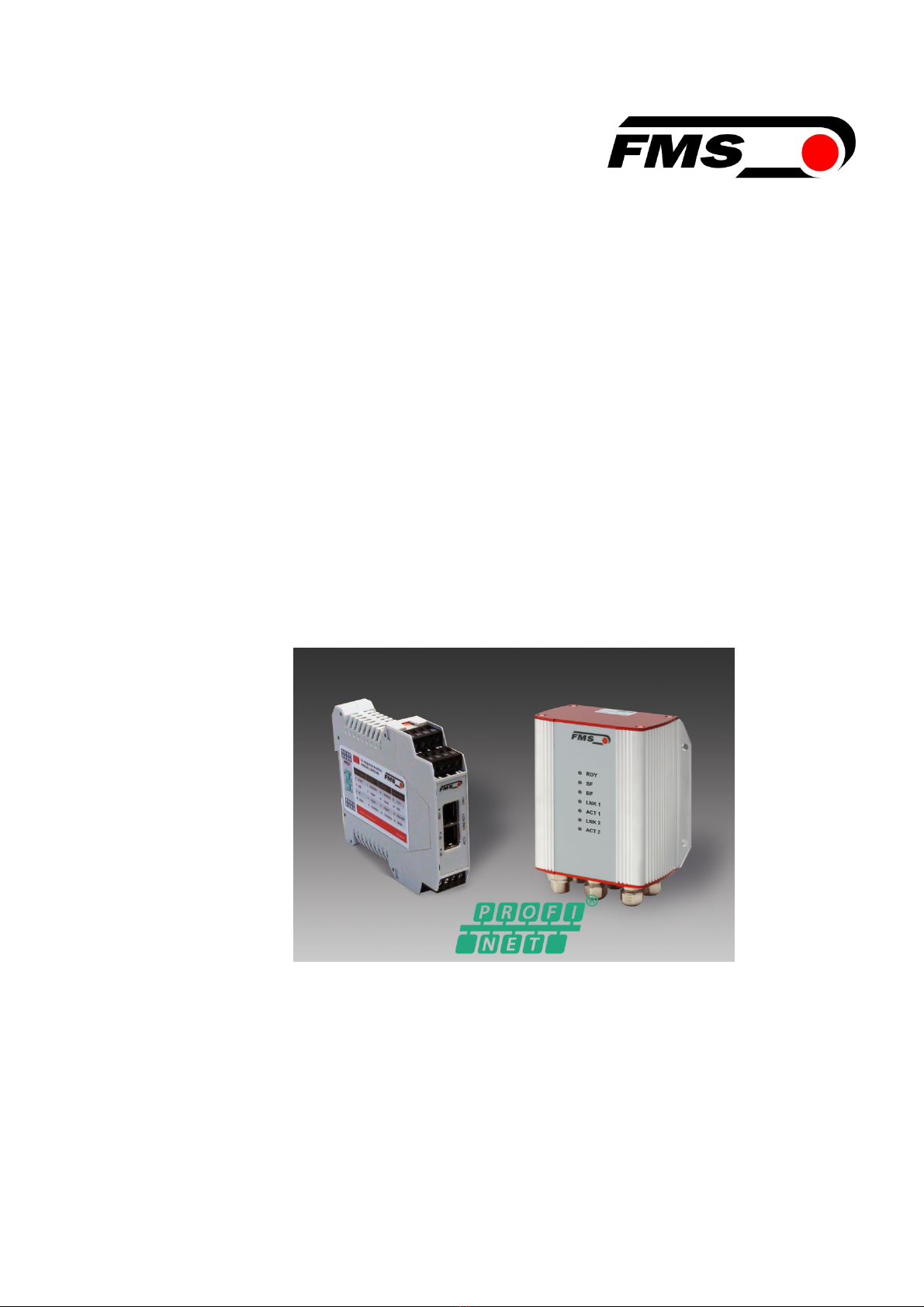
Operating Instructions EMGZ492.PNET
05.10.2018 2
1 Table of Contents
1 TABLE OF CONTENTS ............................................................................................................................. 2
2 SAFETY INFORMATION ........................................................................................................................... 4
2.1 Presentation of Safety Information ..................................................................................................... 4
2.1.1 Danger that Could Result in Minor or Moderate Injuries ............................................................... 4
2.1.2 Note Regarding Proper Function ................................................................................................... 4
2.2 General Safety Information ................................................................................................................ 5
3 PRODUCT DESCRIPTION ........................................................................................................................ 6
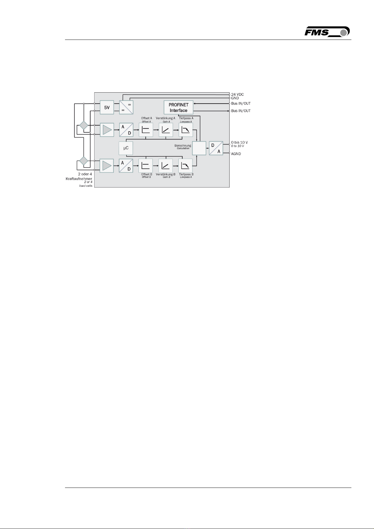
3.1 Block Diagram .................................................................................................................................... 6
3.2 System Description ............................................................................................................................ 6
3.3 Scope of Delivery ............................................................................................................................... 6
4 QUICK GUIDE/QUICK START .................................................................................................................. 7
4.1 Preparations for Parameterization ..................................................................................................... 7
4.2 Mounting Sequence ........................................................................................................................... 7
4.3 Mounting and Electrical Connections ................................................................................................. 7
4.4 Load Cell Mounting ............................................................................................................................ 8
4.5 Electrical Connections ........................................................................................................................ 8
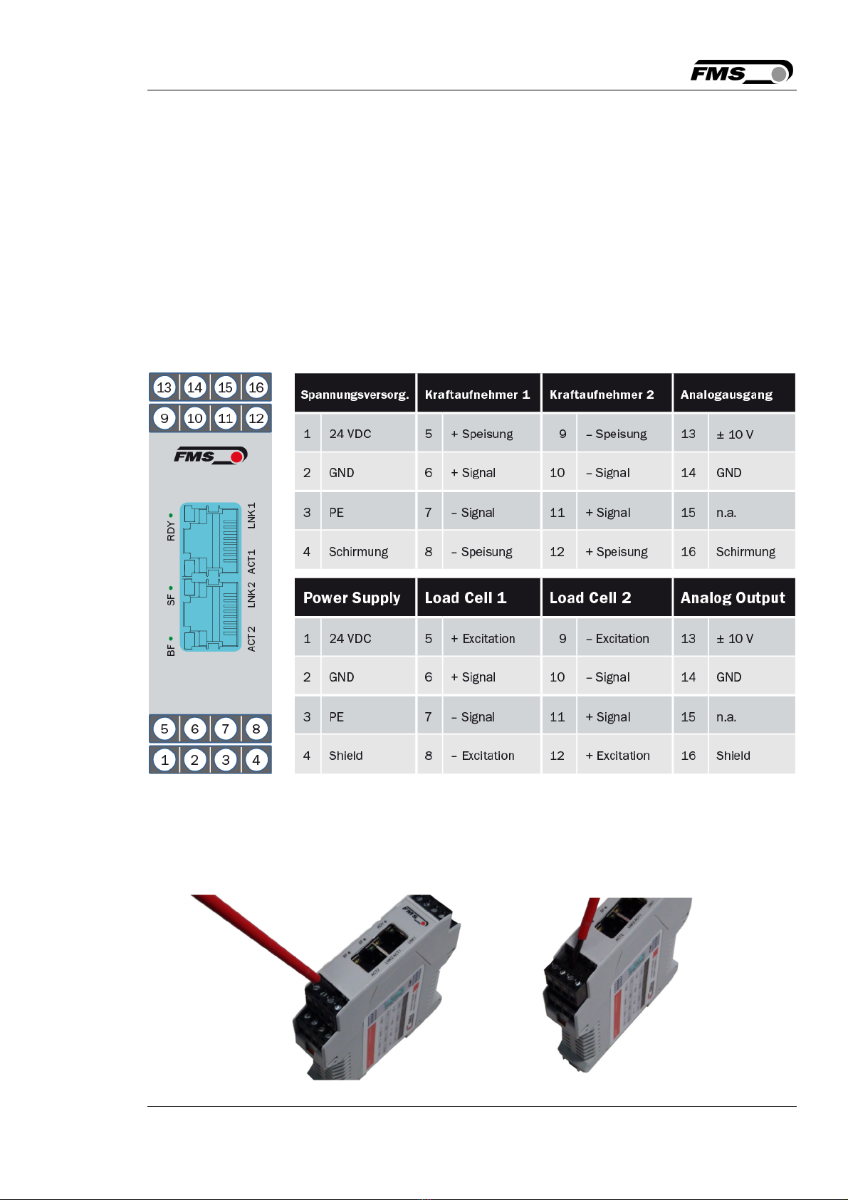
4.5.1 EMGZ492.R.PNET ........................................................................................................................ 8
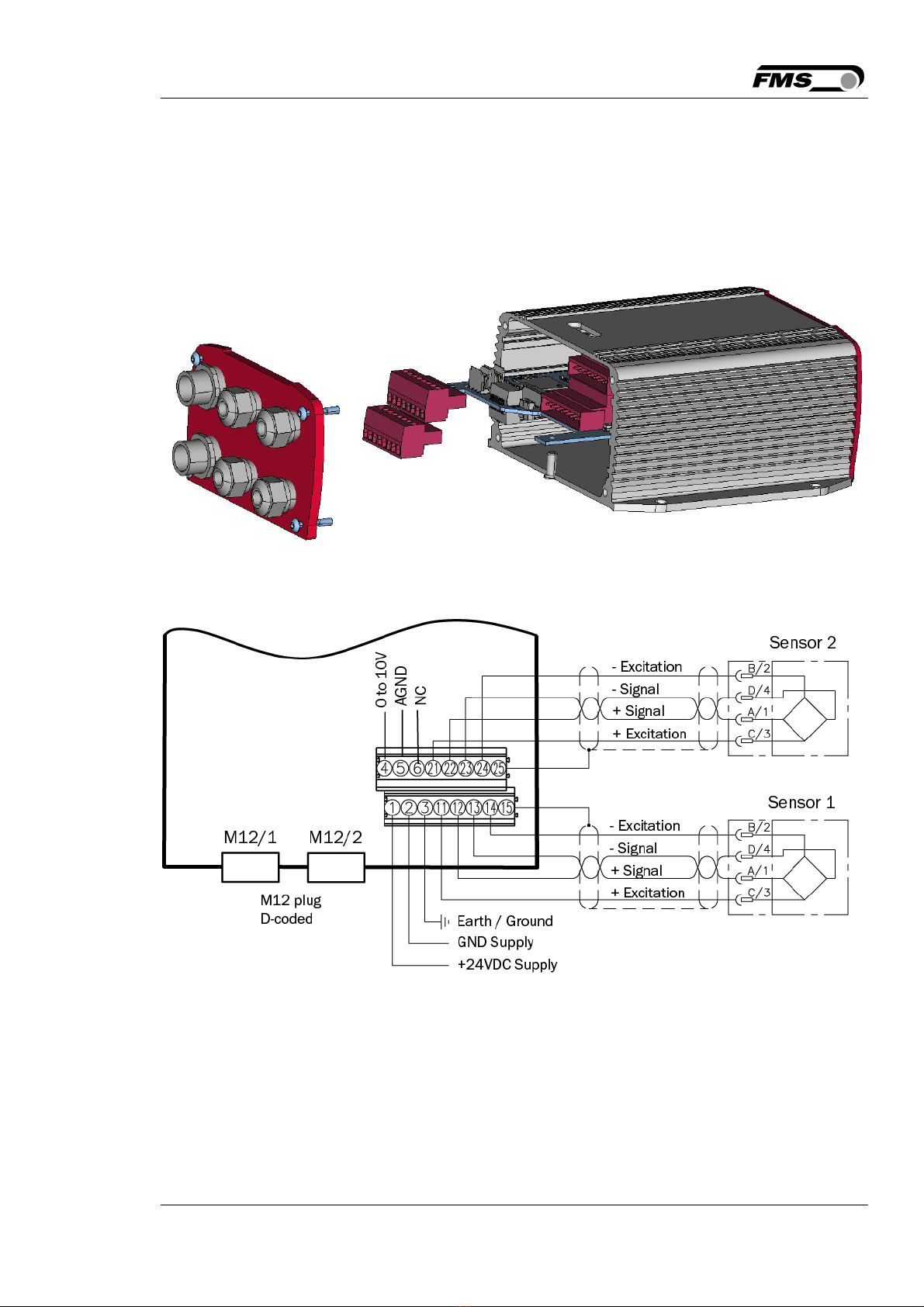
4.5.2 EMGZ492.W.PNET ....................................................................................................................... 9
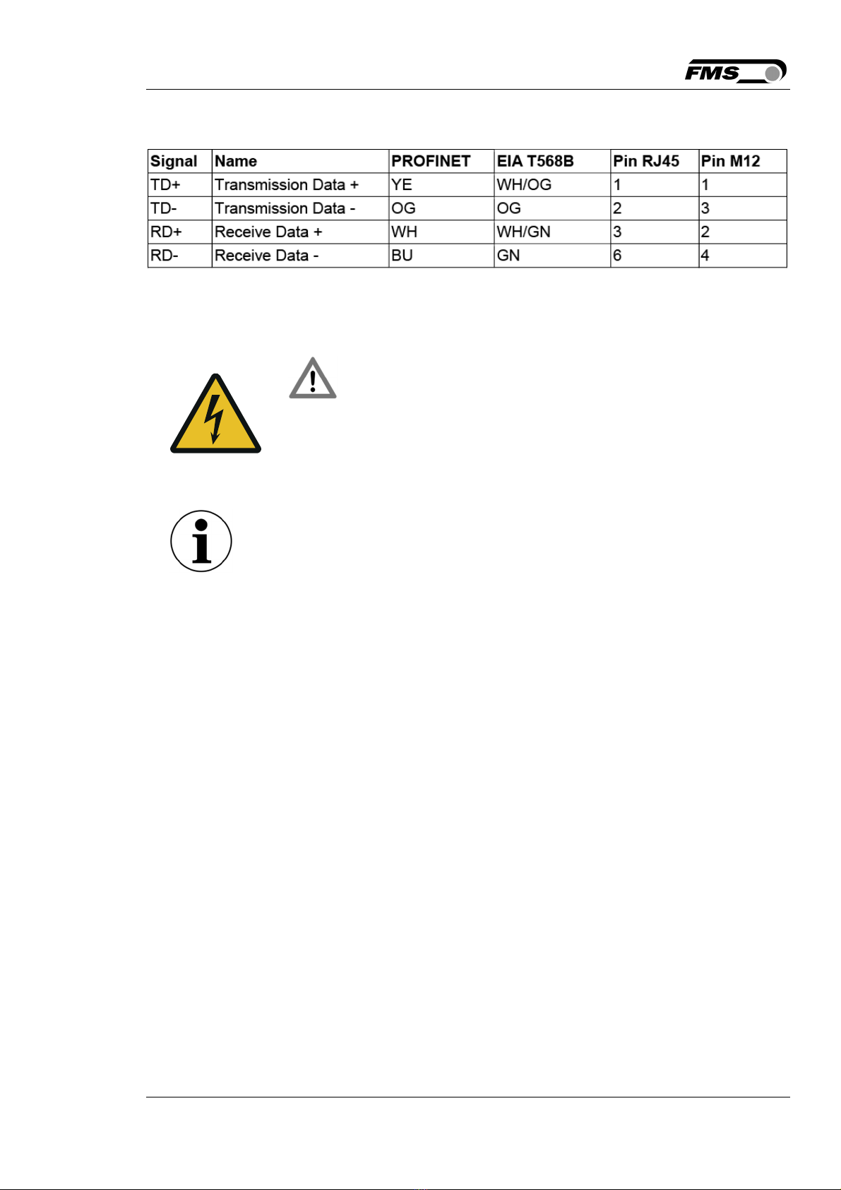
4.5.3 Ethernet Anschlüsse .................................................................................................................... 10
5 CALIBRATION OF THE MEASURING SYSTEM .................................................................................... 11
5.1 Offset Compensation ....................................................................................................................... 11
5.2 Calibration (Adjusting the Gain Factor) ............................................................................................ 11
5.3 Calibration ........................................................................................................................................ 12
5.4 Gain .................................................................................................................................................. 12
5.5 Limit Value Violations ....................................................................................................................... 13
5.5.1 Overload Test .............................................................................................................................. 13
5.5.2 Overflow and Underflow Test ...................................................................................................... 14
5.6 Description of the LEDs ................................................................................................................... 14
6 INTEGRATION INTO THE PROFINET NETWORK ................................................................................ 15
6.1 PROFINET Interface ........................................................................................................................ 15
6.2 TCP/IP Configuration ....................................................................................................................... 15
6.3 System Start ..................................................................................................................................... 15
6.4 Data Exchange ................................................................................................................................. 15
7 CONFIGURATION .................................................................................................................................... 16
7.1 Parameter Description ..................................................................................................................... 16
7.2 Cyclic Data Traffic ............................................................................................................................ 19
7.3 Acyclic Data Traffic .......................................................................................................................... 22
8 PROFINET COMMUNICATION ............................................................................................................... 30
8.1 General Function .............................................................................................................................. 30
8.2 Services and Protocols .................................................................................................................... 30
9 WEB INTERFACE .................................................................................................................................... 31
9.1 Amplifier Access via Web Interface ................................................................................................. 31
9.2 Parameter Settings .......................................................................................................................... 33
9.3 Offset Adjustment and Calibration via Web Browser ....................................................................... 34
9.4 Ethernet Settings .............................................................................................................................. 35
9.5 System Settings ............................................................................................................................... 36