FMS EMGZ308 User manual

Operating Manual EMGZ308
Analog Tension Measuring Amplifier
Version 2.03 04/08 st
This operation manual is also available in German.
Please contact your local representative.
Diese Bedienungsanleitung ist auch in Deutsch erhältlich.
Bitte kontaktieren Sie die Vertretung im zuständigen Land.
© by FMS Force Measuring Systems AG, CH-8154 Oberglatt – All rights reserved.

Operating manual EMGZ308
2
1 Safety Instructions
1.1 Description conditions
a) High danger of health injury or loss of life
Danger
This symbol refers to high risk for persons to get health injury or loss life. It has to be
followed strictly.
b) Risk of damage of machines
Caution
This symbol refers to informations, that, if ignored, could cause heavy mecanical damage.
This warning has to be followed absolutely.
c) Notice for proper function
Notice
This symbol refers to an important information about proper use. If not followed,
malfunction can be the result.
1.2 List of safety instructions
Proper function of the Tension Measuring Amplifier is only guaranteed with the
recommended application of the components. In case of other arrangement, heavy
malfunction can be the result. Therefore, the installation instructions on the
following pages must be followed strictly.
Local installation regulations are to preserve safety of electric equipment. They are
not taken into consideration by this operating manual. However, they have to be
followed strictly.
Improper handling may damage the fragile electronic equipment! Don’t touch the
electronic unit! Don’t use rough tools as screwdrivers or pliers! Touch earthed metal
part to discharge static electricity before touching the electronic unit!
Bad earth connection may cause electric shock to persons, malfunction of the total
system or damage of the electronic unit! It is vital to ensure that proper earth
connection is done.

Operating manual EMGZ308
3
Table of contents
1Safety Instructions ....................................................................................2
1.1 Description conditions 2
1.2 List of safety instructions 2
2Definitions..................................................................................................4
3System components...................................................................................4
4System description ....................................................................................5
4.1 Functional description 5
4.2 Force sensors 5
4.3 Measuring amplifier EMGZ308 5
4.4 Block diagram 6
5Dimensions.................................................................................................7
6Installation and wiring..............................................................................8
6.1 Mounting and wiring of the electronic unit 8
6.2 Mounting the force sensors 9
6.3 Wiring 9
7Setting into operation ..............................................................................10
7.1 View of the setting elements 10
7.2 Configuring gain and offset 10
7.3 Configuring the output 11
7.4 Configuring the lowpass filter 12
7.5 Calibrating the measuring amplifier 13
7.6 Scaling the integrated display 13
8Trouble shooting......................................................................................14
9Technical Data.........................................................................................15

Operating manual EMGZ308
4
2 Definitions
Offset:
Correction value for compensation of the zero point difference. Thanks to the offset, it is
ensured that a force of 0N will generate a signal of 0V exactly.
Gain:
Amplification factor for the measuring signal. Use of proper value will set the measuring
range of the sensor exactly corresponding to the signal output range (0...10V).
Strain gauge:
Electronic component that will change its resistance while its length has changed. Strain
gauges are used in the FMS force sensors for acquisition of the feedback value.
3 System components
The EMGZ308 consists of the following components (refer also to fig. 1):
Force sensors
• For mechanical/electrical conversion of the tension force
• Force measuring bearing (load cell)
• Force measuring roller
• Force measuring journal
• Force measuring bearing block
Measuring amplifier EMGZ308
• Hybrid module for supplying the force sensors and amplification of the mV signal
• One single electronic board may contain up to 2 hybrid modules
• Design with robust aluminium housing
• Gain and offset alternatively configurable for infinitely or fixed adjustment
• Freely configurable lowpass filter
• Freely configurable outputs (±10V; 0...20mA; 4...20mA)
• Integrated digital display
• Supports connection of an external feedback display
(Italic components as variant or option)

Operating manual EMGZ308
5
4 System description
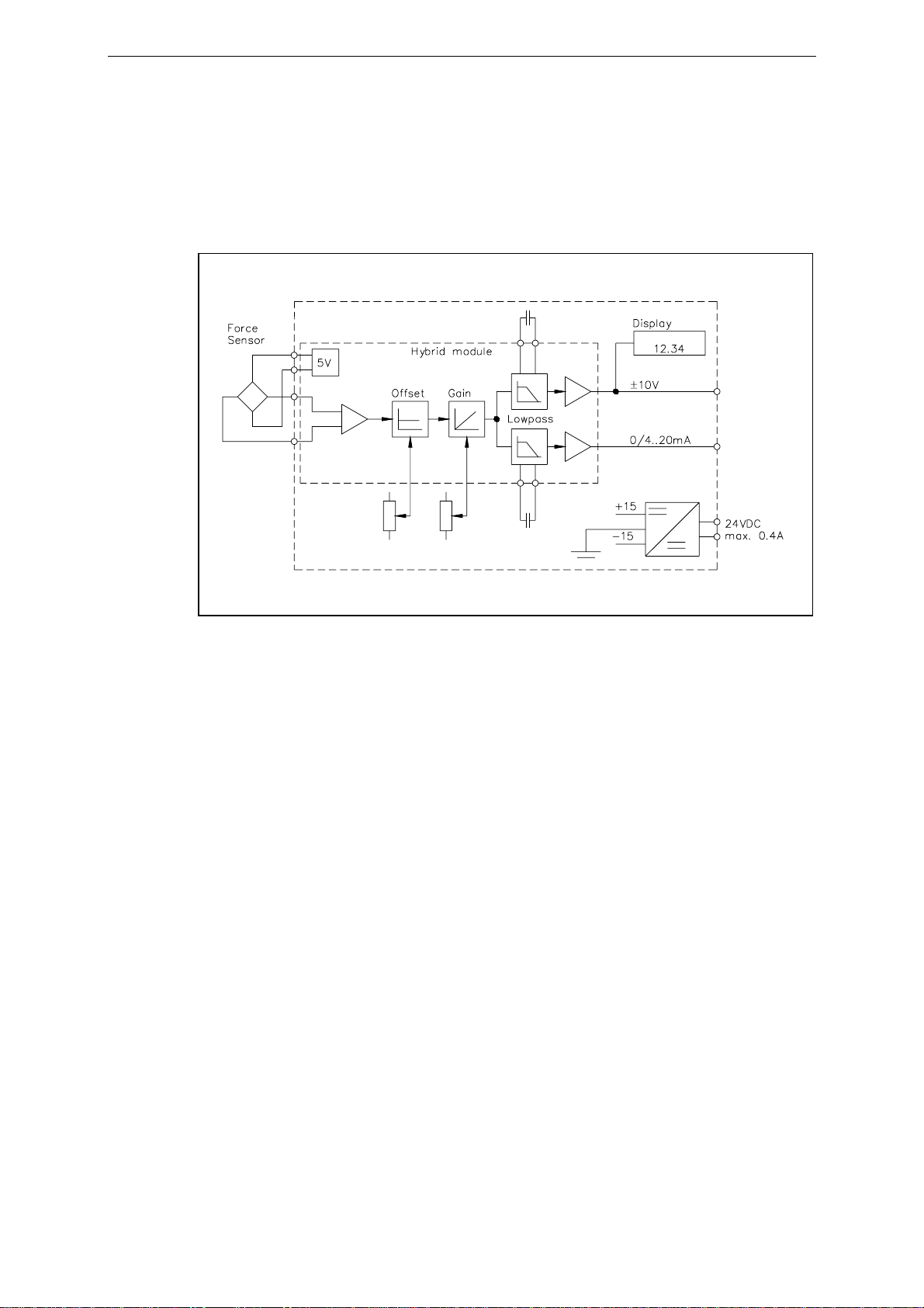
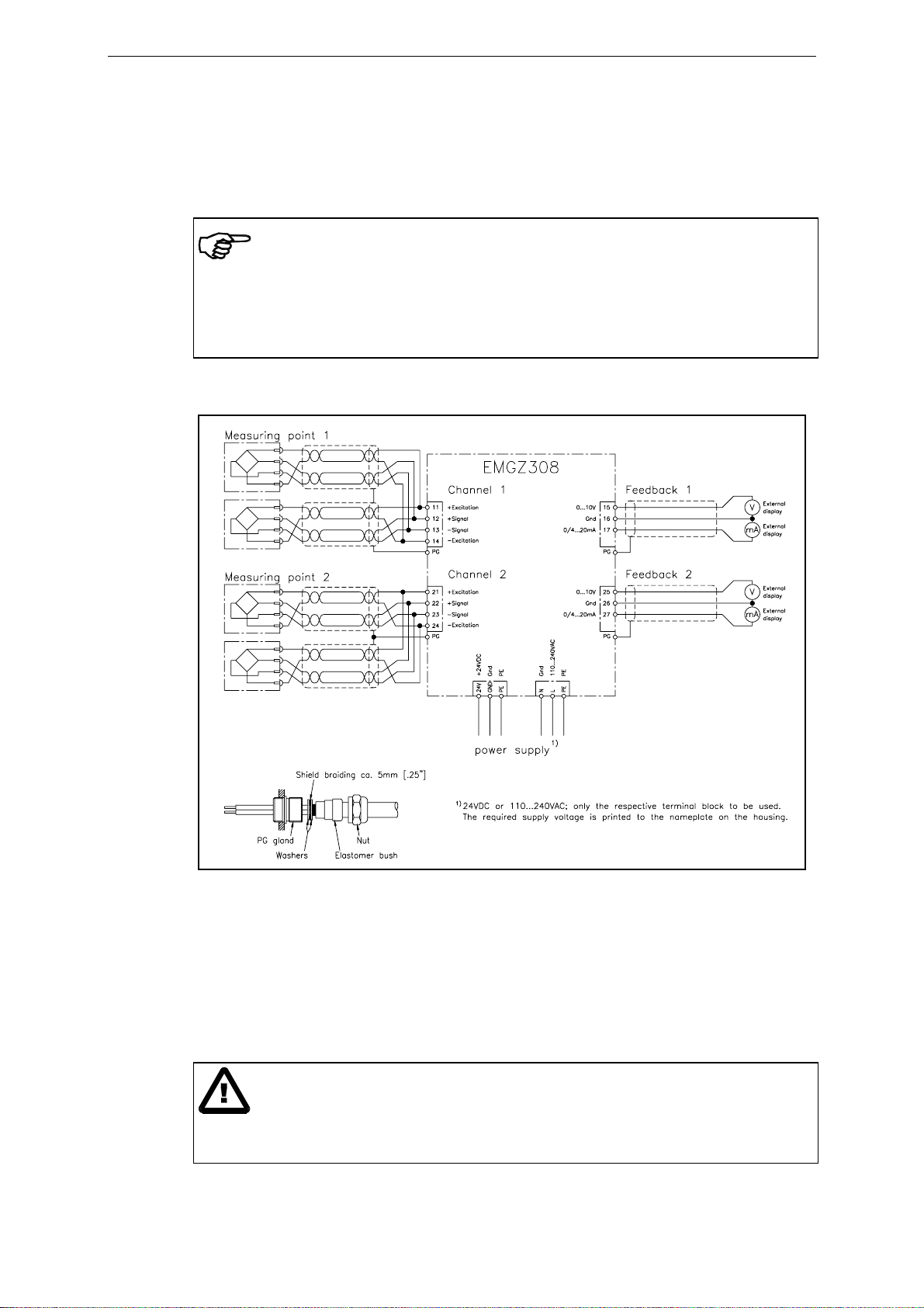
fig. 1: Basic structure of the EMGZ308 Tension Measuring Amplifier (picture shows
single channel version) E308001e
4.1 Functional description
The force sensors measure the tension force in the processed material and transmit the
measuring value as a mV signal to the hybrid module in the measuring amplifier
EMGZ308. The measuring amplifier amplifies the mV signal depending on configuration.
The resulting feedback value can be transmitted to an analog instrument, a PLC or
equivalent devices. In addition, the force value is shown in the integrated digital display.
4.2 Force sensors
The force sensors are based on the flexion beam principle. The flexion is measured by
strain gauges and transmitted to the measuring amplifier as mV signal. Due to the
wheatstone wiring of the strain gauges, the measured value is according also to the power
supply. So, the force sensors are supplied from the EMGZ308 by a very accurate power
supply.
4.3 Measuring amplifier EMGZ308
The EMGZ308 is a single or double channel analog Tension Measuring Amplifier based
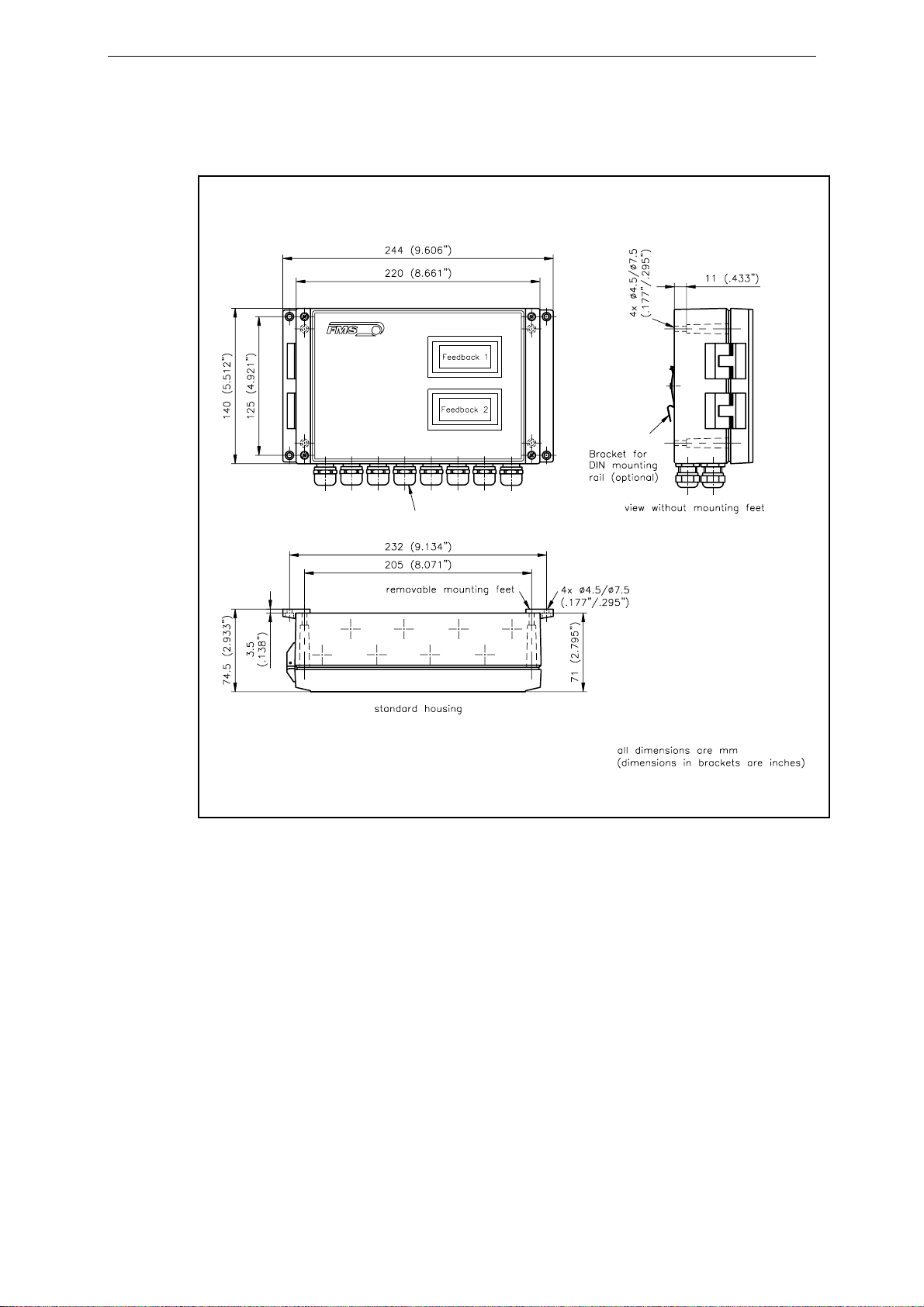
on a hybrid circuit per channel. It is delivered in a robust aluminium housing. All
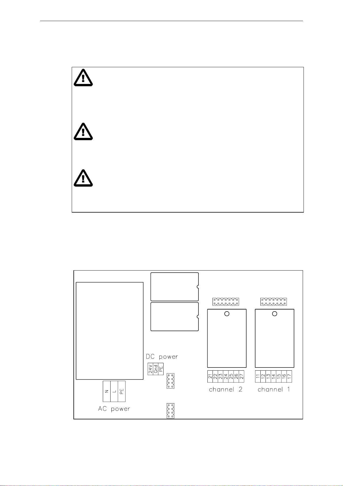
connections are led through glands to screw terminals. There can be connected 1 or 2
force sensors of 350Ωto each channel. The hybrid modules provide the highly accurate
5V power supply and amplify the mV signals of the force sensors to a level of 10V and
20mA. Tension and current output are active the same time. The hybrid technology
ensures both good thermal and electrical characteristics. Measuring circuit and power
supply are galvanic insulated.
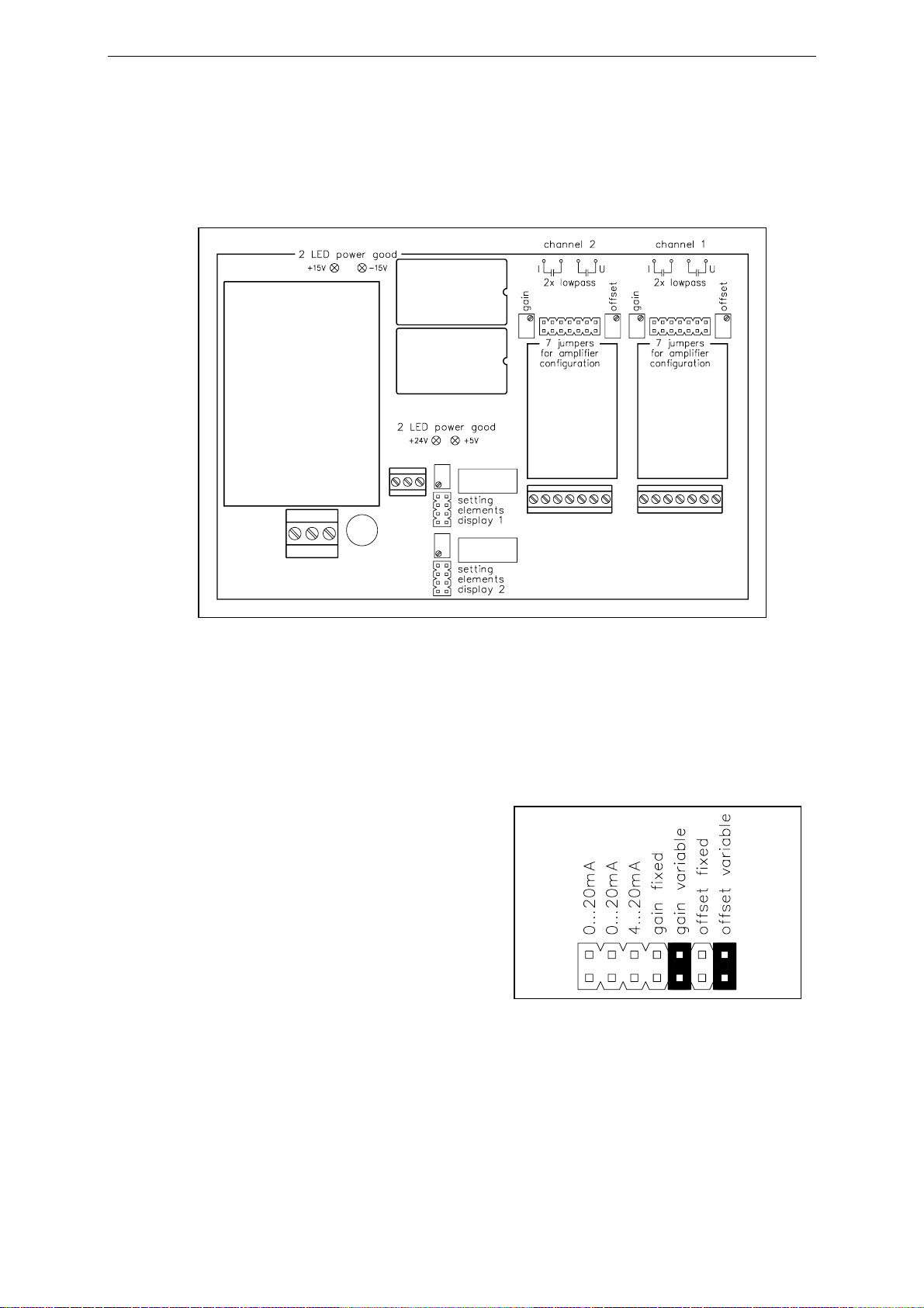
Setting of gain and offset is done by 2 trimmers. For filtering of the signals, non-
polarized capacitors can be soldered.
Infinite adjustment of gain and offset
Setting by trimmers is used to get a standardized output signal (i.e. 10V) from any kind of
sensor signal. This ensures accurate amplifying of the signal and maximum immunity to
any interference of the signal cable.

Operating manual EMGZ308
6
Fixed setting of gain and offset
Fixed setting is used when maximum thermal stability and vibration-proof conditions are
needed. The signal is pre-amplified with a fixed value and has to be evaluated digitally
(for ex. by a PLC), so that offset and gain can be calculated.
4.4 Block diagram
fig. 2: The block diagram shows the single channel version. E308002e

Operating manual EMGZ308
7
5 Dimensions
8 x M16 x 1.5
EMGZ308 SERIES
CHANNEL 1
CHANNEL 2
fig. 3 E308013e

Operating manual EMGZ308
8
6 Installation and wiring
Caution
Proper function of the Tension Measuring Amplifier is only guaranteed with the
recommended application of the components. In case of other arrangement, heavy
malfunction can be the result. Therefore, the installation instructions on the following
pages must be followed strictly.
Caution
Local installation regulations are to preserve safety of electric equipment. They are not
taken into consideration by this operating manual. However, they have to be followed
strictly.
Caution
Improper handling may damage the fragile electronic equipment! Don’t touch the
electronic unit! Don’t use rough tools as screwdrivers or pliers! Touch earthed metal part
to discharge static electricity before touching the electronic unit!
6.1 Mounting and wiring of the electronic unit
The aluminium housing of the measuring amplifier may be mounted to any place in the
machine, but usefully a position close to the force sensors is chosen. Wiring to the
terminals is done according to wiring diagram (fig. 5).
fig. 4: Screw terminal arrangement on the electronic pc board E308009e

Operating manual EMGZ308
9
6.2 Mounting the force sensors
Mounting of the force sensors is done referring to the FMS Installation manual which is
delivered together with the force sensors.
Wiring to the terminals of the electronic unit is done according to wiring diagram (fig. 5).
Notice
Connecting the shield of the signal cable to the electronic unit and to the force sensor
may cause ground circuits which may interfere the measuring signal massively.
Malfunction can be the result. The shield should be connected only to the electronic unit.
On the „force sensor“ side, the shield should stay open.
6.3 Wiring
fig. 5: Wiring diagram E308007e
There can be connected 1 or 2 force sensors per channel. Using 2 force sensors, the
connections will be wired parallel. The output signal of the measuring amplifier then will
correspond to the average value of the 2 sensors.
The connection between force sensors and measuring amplifier has to be done using
2x2x0.75mm2[AWG 18] shielded twisted-pair cable. (With cable length below 15m,
2x2x0.25 mm2[AWG 23] is also suitable.) The cable must be installed separate from
power lines.
Caution
Bad earth connection may cause electric shock to persons, malfunction of the total system
or damage of the electronic unit! It is vital to ensure that proper earth connection is done.

Operating manual EMGZ308
10
7 Setting into operation
7.1 View of the setting elements
fig. 6: Setting elements E308008e
7.2 Configuring gain and offset
Gain and offset are configured by jumpers. The settings can be made individually for
each channel.
Gain and offset with infinite setting
If gain and offset are adjusted with the
trimmers, the jumpers have to be set
according to fig. 7. Gain and offset then
may be adjusted using the trimmers (refer
to „7.5 Calibrating the measuring
amplifier“).
fig. 7: Jumper setting for infinite gain
and offset adjustment E308010a

Operating manual EMGZ308
11
Gain and offset with fixed setting
If the signal is processed by a control unit
(i.e. a PLC), configuration with fixed gain
and offset is recommended (offset = 0;
gain = 1111). Therefore, the jumpers have
to be set according to fig. 8. With this
configuration, the good thermal
characteristics of the hybrid module are
best utilized. The output signal will be
20mA when the nominal force of the
sensor is applied.
7.3 Configuring the output
Each channel provides a voltage output (±10V) and a current output (0...20mA or
4...20mA) which are active simultaneously. The signal of the current output is configured
as follows:
Current output 0...20mA
The jumpers have to be set according to
fig. 9. This is the standard FMS factory
setting.
Current output 4...20mA
The jumpers have to be set according to
fig. 10.
fig. 8: Jumper setting for fixed gain
and offset E308010b
fig. 9: Jumper setting for current
output 0...20mA E308010c
fig. 10: Jumper setting for current
output 4...20mA E308010d

Operating manual EMGZ308
12
7.4 Configuring the lowpass filter
The measuring amplifier provides 2 lowpass filters per channel. They are used to
eliminate faulty signal variations which may be caused by unbalanced rollers, vibrations
of the machine, or equivalent.
Lowpass U acts only to the tension output
Lowpass I acts only to the current output
The lower the cut-off frequency, the more sluggish the signal will be. The configuration
is made by soldering a non-polarized capacitor to the respective soldering points (refer to
fig. 6). The capacitor will be determined referring to the following formula or table:
Cut-off frequency
[Hz] Capacitor [µF]
1 10
C = 10 / F 2 5
5 2
10 1
C: Capacity [µF] 20 0.5
F: Cut-off frequency [Hz] 50 0.2
100 0.1
200 0.05
500 0.02
1000 0.01
Notice
You must not use electrolytic capacitors because positive and negative signals are
appearing! They would damage the electrolytic capacitor.

Operating manual EMGZ308
13
7.5 Calibrating the measuring amplifier
Proceed the calibration for each channel as follows:
• Connect gauge to the tension or current output.
• Connect the first force sensor.
• Check if a positive output signal is appearing when loading the sensor in measuring
direction. If not, exchange the two signal wires of the referring force sensor in the
terminal block (+Signal and –Signal).
• If used, connect the second force sensor.
• Check if a positive output signal is appearing when loading the sensor in measuring
direction. If not, exchange the two
signal wires of the referring force
sensor in the terminal block (+Signal
and –Signal).
• Insert material or a rope loosely to the
machine.
• Adjust the offset trimmer until the
output value is zero.
• Load material or rope with a defined
weight (fig. 11).
• Adjust the gain trimmer until the
output value shows the needed value
(i.e. 10V corresponding to 500N).
Notice
If the measuring amplifier is operated with fixed gain and offset, signal conditioning has
to be done with additional equipment (for ex. PLC).
7.6 Scaling the integrated display
After configuring offset and gain, scale the
value shown in the display of the respective
channel as follows:
• Scale the display value with trimmer
„scale display“ (fig. 12).
• Set the jumper „set decimal point“
(fig. 12) in the position which gives a
correct decimal point in the display.
• Close the housing.
fig. 11: Calibrating the measuring amplifier
fig. 12: Display setting elements
E308011e

Operating manual EMGZ308
14
8 Trouble shooting
Error Cause Corrective action
Output shows signal > 0
although material has no
tension
Offset setting is bad Re-adjust offset (refer to „7.5 Calibrating the
measuring amplifier“)
Current output is configured
for 4...20mA Change jumper setting if required
Output signal is not
stable although material
tension doesn’t change
Cut-off frequency too high Adjust cut-off frequency (refer to
„7.4 Configuring the lowpass filter“)
Ground terminal of the output
isn’t 0V Connect Gnd terminal of the output with earth
(terminal PE)
Adjusting of the
trimmers causes no
result
Jumpers are set to
„fixed gain“ / „fixed offset“ Set jumpers to „variable gain“ / „variable offset“
Display shows inaccurate
value Display scaling not correct Proceed display scaling (refer to „7.6 Scaling the
integrated display“)
Output shows no
reaction, or 1 or 2 LED’s
don’t light
Fuse blown Replace fuse on power supply
Power supply not correct Check / correct power supply
Measuring amplifier defect Contact FMS customer service

Operating manual EMGZ308
15
9 Technical Data
Sensor excitation 5VDC ±20ppm/K max. 30mA [±11ppm/°F]
Gain factor range fixed: 1111; variable: 500...5000
Offset range fixed: 0mV; variable: ±9mV
Temperature drift offset fixed: < 20ppm/K [11ppm/°F]; variable: ca. 50ppm/K [28ppm/°F]
Linearity error < 0.1%
Tension output ±10V min. 1kΩ
Current output 0/4...20mA max. 500Ω
Lowpass cut-off frequency adjustable, ca. 1...1000Hz
Power supply 24VDC or 100...240VAC max. 0.2A (see name plate)
Power consumption max. 2.5W
Temperature range –10...+60°C [14...140°F]
Protection class IP54

Operating manual EMGZ308
16
FMS Force Measuring Systems AG
Aspstrasse 6
8154 Oberglatt (Switzerland)
Tel. 0041 44 852 80 80
Fax 0041 44 850 60 06
info@fms-technology.com
www.fms-technology.com
FMS USA, Inc.
925 East Rand Road Suite 207
Arlington Heights, IL 60004 (USA)
Tel. 847 392 7872
Fax 847 392 7873
fmsusa@fms-technology.com
FMS (UK)
Highfield, Atch Lench Road
Church Lench
Evesham WR11 4UG (Great Britain)
Tel. 01386 871023
Fax 01386 871021
fmsuk@fms-technology.com
Table of contents
Other FMS Amplifier manuals
Popular Amplifier manuals by other brands

ALLNIC AUDIO
ALLNIC AUDIO A-2000 25th Anniversary SE owner's manual

Yamaha
Yamaha A-S801 owner's manual

ADC
ADC ClearGain Tower-Mounted Amplifiers Specification sheet

Engl
Engl Tube Preamp 530 Operator's manual

Cobalt Digital Inc
Cobalt Digital Inc 9001 owner's manual

JBL
JBL GTR-7535/104/102 quick start guide