FMS EMGZ321 Series User manual

Operating Manual EMGZ321
Digital microprocessor controlled
Double Channel Tension Measuring Amplifier
Version 1.02 01/2010 ff
Firmware Version: 1.02
This operation manual is also available in German.
Please contact your local FMS representative.
Diese Bedienungsanleitung ist auch in Deutsch erhältlich.
Bitte kontaktieren Sie Ihren nächstgelegenen FMS Vertreter.
© by FMS Force Measuring Systems AG, CH-8154 Oberglatt – All rights reserved.

Operating Manual EMGZ321
2
Table of Contents
1Safety Instructions .................................................................................... 4
1.1 Description Conditions 4
1.2 List of Safety Instructions 4
2System Description.................................................................................... 6
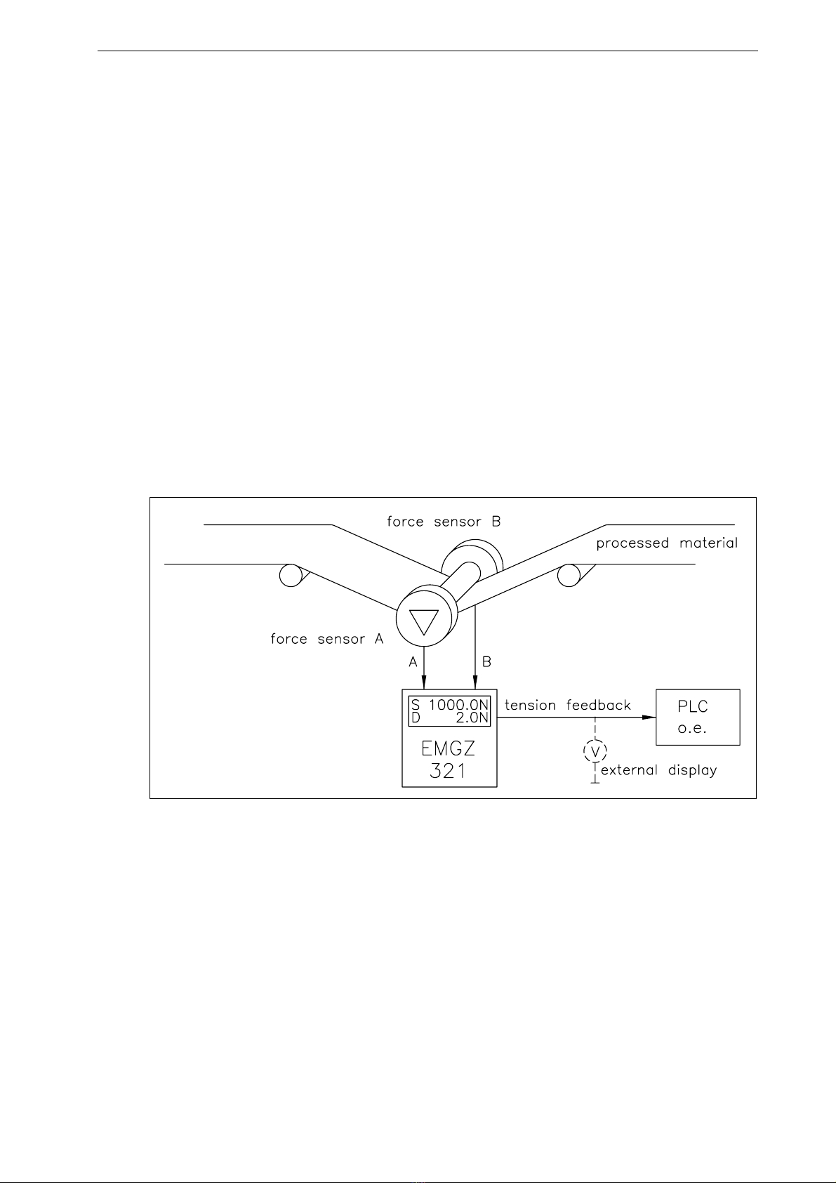
2.1 Functional Description 6
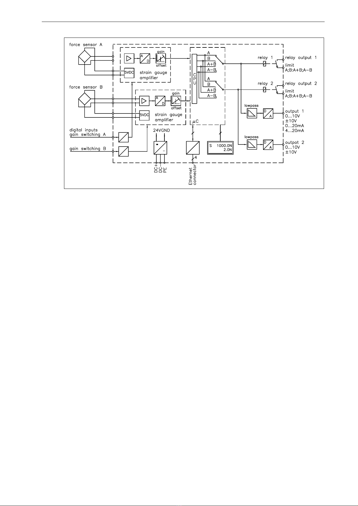
2.2 EMGZ321 Amplifier and its Subunits 6
2.3 EMG321 Sub Types 8
3Quick Installation Guide .......................................................................... 9
3.1 Preparations for Set-up 9
3.2 Installation Procedure 9
4Installation and Wiring .......................................................................... 10
4.1 Mounting the Force Measuring Roller 10
4.2 Mounting the EMGZ321 10
4.3 Wiring the Tension Monitoring System 11
4.4 Screw Terminal Arrangement 12
4.5 Connection of the Cable Shield 13
4.6 Digital Inputs 13
4.7 Relays Outputs 14
4.8 Opening the Housing 14
5Configuring the System .......................................................................... 15
5.1 Description of the Operating Panel 15
5.2 Preparations for System Configuration 16
The default setting for the language is English. 16
6Operation ................................................................................................. 18
6.1 Operating the EMGZ321 over the Front Panel 18
6.2 Display Value Selection State 19
6.3 Offset Compensation Procedure 19
6.4 Calibration Methods 20
6.5 Calibration Procedure: 20
7Parameter Setting over the Front Panel ............................................... 22
7.1 Basic Instructions for Parameter Setting 22
7.2 Amplifier Parameter Group 23
7.3 Description of Amplifier Parameters 24
7.4 Outputs Parameter Group 25
7.5 Description of Output Parameters 27
7.6 Relay Parameter Group 29
7.7 Description of Relay Parameters 31
7.8 System Parameter Group 33
7.9 Description System Parameters 36
7.10 Reset to Default Parameters 38
7.11 Complete Parameter List 39
8Parameter Setting via a PC .................................................................... 42
8.1 Parameterisation in an Ethernet Network via Web Browser 43

Operating Manual EMGZ321
3
8.2 Parameterization via a PC (peer-to-peer connection) 49
9Mechanical Dimensions .......................................................................... 52
10 Trouble Shooting..................................................................................... 54
11 Technical Specification ........................................................................... 55
11.1 Technical Data 55
11.2 Input / Output Configuration 55

Operating Manual EMGZ321
4
1Safety Instructions
All safety related regulations, local codes and instructions that appear in the manual or on
equipment must be observed to ensure personal safety and to prevent damage to the
equipment connected to it. If equipment is used in a manner not specified by the
manufacturer, the protection provided by the equipment may be impaired.
Do not stress the equipment over the specification limits neither during assembly nor
operation. To do so can be potentially harmful to persons or equipment in the event of a
fault to the equipment.
1.1 Description Conditions
a) Danger of health injury or loss of life
Danger
This symbol refers to high risk for persons to get health injury or loss life. It has to be
followed strictly.
b) Risk of damage of machines
Caution
This symbol refers to information, that, if ignored, could cause heavy mechanical
damage. This warning has to be followed absolutely.
c) Note for proper function
Note
This symbol refers to an important information about proper use. If not followed,
malfunction can be the result.
1.2 List of Safety Instructions
Some of the wire terminals in the power supply board of the EMGZ321W.ACV are
under a tension of 85-264 VAC. Mortal danger! Only specially instructed and qualified
personnel should handle this amplifier unit. In any case the power supply must be
disconnected from the main supply before opening the housing.
Proper function of the FMS tension controllers is only guaranteed with the
recommended application of the components. In case of other arrangement, heavy
malfunction can be the result. Installation instructions on the following pages must be
followed strictly.

Operating Manual EMGZ321
5
Local installation regulations are to preserve safety of electric equipment. They are not
taken into consideration by this operating manual. However, they have to be followed
strictly.
Bad earth connection may cause electric shock to persons, malfunction of the total
system or damage of the control unit. It is vital to ensure a proper earth ground
connection.
The processor board is mounted directly behind the operation panel. Improper handling
of the electronic boards may cause damage to the fragile equipment. Don’t use rough
tools such as screwdrivers or pliers! Operators handling the electronic boards must wear
a well earthed bracelet in order to discharge static electricity.

Operating Manual EMGZ321
6
2System Description
2.1 Functional Description
The EMGZ321 is a double channel strain gauge amplifier for a single measuring point.
The material tension can be measured on both sides of the measuring roller
independently.
The 2 force sensors of the measuring point measure the tension force in the material and
transmit the measuring value as a mV signal to the electronic unit EMGZ321. The
electronic unit amplifies the mV signal of each force sensor independently. This signal
will be fed to the A/D converter. The microprocessor does then all application specific
calculations such as offset, gain, low-pass filter, limit switches, etc.
A sum value (A+B) and a difference value (׀A-B׀) are calculated from the force values of
the sensors A and B. The resulting feedback values are shown in the display in [N] or the
chosen unit. In addition, the feedback values are provided at the analogue outputs and can
be evaluated by analogue instruments, a PLC or equivalent devices.
Fig. 1: Application example of EMGZ321 E321004e
2.2 EMGZ321 Amplifier and its Subunits
As a plug & play unit all functions of the EMGZ321 can be configured very easily via a
user-friendly control panel and two lines LCD. Tension reference values and all other
parameters and functions can be set with keys or remotely via a web browser. The
amplifier is then either connected to a network or via a peer-to-peer configuration to a
laptop or local PC. All parameters are stored in a none-volatile EEPROM memory.
Automatic offset compensation and calibration, digital signal filtering, function along
with a lot of other features creates a very powerful tension monitoring system. The
fundamental characteristics of the EMGZ321 remain its operation simplicity and
reliability even under challenging operating conditions.

Operating Manual EMGZ321
7
Fig. 2: Block diagram EMGZ321 E321002e
Display and Operation Panel
A dual-line LCD display with 8 characters each line and a well arranged control panel
make the EMGZ321 very easy to set-up and operate. All parameters and functions are
accessible trough the wind rose key pad and three buttons.
Strain gauge amplifier
The build-in strain gauge amplifier delivers a highly accurate supply voltage (5VDC,) for
2 force sensors. The force sensors can be wired using a 4- wire circuitry.
A highly accurate differential amplifier rises the mV sensor signal up to 10V.
Force Sensors
The force sensors are based on the flexion beam principle. The flexion is measured by
strain gauges and transmitted to the electronic unit as mV signal. Due to the wheatstone
bridge configuration of the strain gauges, the measured value is proportional to the power
supply. EMGZ4321 provides a very accurate power supply for the wheatstone bridge.
Interface
The EMGZ321 can be embedded in an Ethernet network and the communication is via a
web browser (Ethernet explorer 7 or higher).

Operating Manual EMGZ321
8
2.3 EMG321 Sub Types
EMGZ321.R / .S / .W / .W.ACV
The tension controller EMGZ321 series is available in three different housing options.
EMGZ321.R: Rail mount housing
EMGZ321.S: Panel mount housing
EMGZ321.W / W.ACV Wall mount housing
Detailed information about the mechnical dimensions refer to the outline drawings Fig.
30 to 32.
EMGZ321.W.ACV
The tension controller type EMGZ321.W.ACV includes a separate power supply that
supports voltage of 85V up to 264V. It transforms the AC input voltage into DC 24V for
the internal system components.

Operating Manual EMGZ321
9
3Quick Installation Guide
In a Plug & Play configuration the set-up of the EMGZ321 and force sensors is straight
forward and limited to only the offset compensation and the calibration procedure.
3.1 Preparations for Set-up
1. Read the Operation Manual of your force measuring sensors and amplifier
2. Check your requirements such as:
– Desired output configuration 0…10V, ±10V or 0/4… 20mA
– Display unit of nominal force
3. Draw the wiring diagram for your configuration (ref. to “3.5 Wiring the Amplifier“)
4. If required, determine special parameters (ref. to “5.2 Parameterization for System
Configuration”)
3.2 Installation Procedure
1. Mount your force maesuring roller to the machine frame.
2. Wire the force measuring sensors (ref. to “4.3 Wiring the Tension Monitoring
System”)
3. Connect the amplifier to the power supply.
4. The power supply voltage must be in the range 18 to 36V DC.
5. Perform offset compensation and calibration (ref. to paragraphs 4.1 to 4.4)
6. If required, do additional settings (ref. to “5.2 Parameterization for System
Configuration”)

Operating Manual EMGZ321
10
4Installation and Wiring
Caution
Proper function of the FMS tension amplifier is only guaranteed with the recommended
application of the components. Other arrangements, can cause heavy malfunctions.
Installation instructions on the following pages must strictly be followed.
Caution
Local installation regulations are to preserve safety of electric equipment. They are not
taken into consideration by this operating manual. However, they have to be followed
strictly.
4.1 Mounting the Force Measuring Roller
Mounting of the force sensors is done according to the FMS installation manual which is
delivered together with the force sensors.
4.2 Mounting the EMGZ321
The EMGZ321 series is available in 3 different housing options. The respective
mechanical dimensions of the different housings can be seen in paragraph 15.

Operating Manual EMGZ321
11
4.3 Wiring the Tension Monitoring System
Use the original FMS cables to connect the system components together.
The connection between the force sensors and the electronic unit is done with a 2x2x0.25
mm2[AWG 23] cable. The wiring diagrams show how the wiring to the terminals of the
electronic unit is done.
Fig. 3: Wiring diagram EMGZ321 E321001e
Caution
Bad earth connection may cause electric shock to persons, malfunction of the total system
or damage of the control unit. It is vital to ensure that there is a proper and secure earth
ground connection.

Operating Manual EMGZ321
12
4.4 Screw Terminal Arrangement
Fig. 4: Screw terminal arrangement on processor board E321003e

Operating Manual EMGZ321
13
4.5 Connection of the Cable Shield
Cable shields must be connected
as indicated in the wiring
diagram (see Fig. 3 and 4). The
shield should be connected only
to the amplifier side. On the
force sensor side, the shield
should stay open. Other
arrangements may cause
ground/earth loops which may
interfere with the measuring
signal. Malfunction can be the
results. If a housing type with PG glands is used, one must pay heed to a proper connection of
the shield. Skinning of the cable and shield handling are indicated in Fig. 5.
Note
Force sensors deliver a signal of a few mV and are therefore susceptible to external
influences. To increase immunity to interfering use one twisted pair cable for +signal and
–signal. This signal cables must be separated from power lines.
Note
Connecting the shield of the signal cable to the electronic unit and to the force sensor
may cause ground loops which may interfere with the measuring signal. Malfunction can
be the result. The shield should be connected only to the electronic unit. On the „force
sensor side“, the shield should stay open.
4.6 Digital Inputs
The EMGZ321 controller provides 2 digital inputs for the special functions of switching
between two different gain factors.
The digital inputs are level triggered. A threshold change activates the gain switch:
•In sensor A from gain factor 1 to gain factor 2
•In sensor b from gain factor 1 to gain factor 2
Signal Name Terminal # Sensor Threshold low Threshold high
Dig. In 1 5 A Gain factor 1 Gain factor 2
Dig. In 2 6 B Gain factor 1 Gain factor 2
Fig. 5: Shield connection E470009e

Operating Manual EMGZ321
14
4.7 Relays Outputs
The EMGZ321 controller provides 2 programmable relay outputs. The outputs are
software controlled. Electrically they are potential-free. Each relay output can
individually be configured to check violations of force limits. The outputs are configured
in the “Relay Parameter Group”.
Following functions can be assigned to each output:
•Indicate if force limit of sensor A has bee violated
•Indicate if force limit of sensor B has bee violated
•Indicate if the sum of the forces of sensor A+B has bee violated
•Indicate if the absolute value of difference ׀A-B׀has bee violated
For more details about the functions refer to paragraph 7.7 “Description Relay Parameter
Group”.
Hardware access via screw terminals (see Fig. 3 and 4)
Signal Name Terminal #
Relay 1/1 7
Relay 1/2 8
Relay 2/1 9
Relay 2/2 10
4.8 Opening the Housing
The amplifier versions EMGZ321.W.ACV is supplied by main supply (85 to 264V AC).
The housings of these controller versions can be opened by removing the front cover to
the screw terminals. This may not be done if the unit is connected to main supply.
Handling of the main supply versions should take place with special care and only by
specially instructed and qualified personnel.
Danger
Some of the wire terminals in the power supply board of the EMGZ321W.ACV are under
a tension of 85-264 VAC. Mortal danger! Only specially instructed and qualified
personnel should handle this amplifier unit. In any case the power supply must be
disconnected from the main supply before opening the housing.

Operating Manual EMGZ321
15
5Configuring the System
After having mounted and wired the tension controller on the machine, the system can
now be configured to the specific requirements of the application.
5.1 Description of the Operating Panel
Fig. 6: View of the Operating Panel EMGZ309.W C309009
The keys on the operating panel have the following functions:
Key Key function during operation
Enter Offset Compensation Procedure
Enter Calibration Procedure
To enter the Parameter Setting Mode, press the key for longer then 3
sec. The LED will light and the first parameter group will appear on
the LCD display indicating that you entered the mode. The State
Diagrams (Fig. 12 to 29) in paragraph 7 “Parameter Setting over the
Front Panel” will help you to navigate in the parameter setting
mode.
Enter
Changes the parameter selection.
Increases the parameter values. Pressing the button increases
continuously the parameter value.
Decreases the parameter values. Pressing the button reduces
continuously the parameter value.
Fig. 7: Functions of the operation panel keys

Operating Manual EMGZ321
16
5.2 Preparations for System Configuration
In order to facilitate the configuration of the tension monitoring system it is advisable to
adapt some basic system parameters to the specific requirement of the application.
1. Adopt password
2. Set the language on the display
3. Set measuring unit
Above features are changed in the “7.8 System Parameter Group”. Please refer to Fig. 17
to 19 to visualise the following parameter changing procedures:
A) Adopt Password
The password can not be changed. It is always 3231. However, it can be adopted or
disabled. If adopted, the system will request the password for every parameter change. If
you wish to adopt the password, follow the following instructions:
1. Hold the key for longer then 3 sec. until you enter the Parametrisation State.
2. The display shows . Scroll the menu by pressing the key until you
are in the parameter group “System”.
3. Press . The display shows .
4. Press again . The display starts flashing indicating that you can now change the
parameter with the or keys.
5. To confirm your change by pressing the Enter key .
6. Press the key twice, if you want to return to the Operation State. If you desire to
change the language, continue with the steps below.
B) Change Language
The default setting for the language is English.
1. Press to select the Parameter Language
2. Press again . The display starts flashing indicating that you can now change the
parameter with the or keys.
3. To confirm your change by pressing the Enter key .
4. Press the key twice, if you want to return to the Operation State. If you desire to
change the measuring unit, continue with the steps below.
Language
No / Yes
Password
No
Amp.
********

Operating Manual EMGZ321
17
C) Change the Measuring Units
The default tension measuring unit is N (Newton). The user can, however, select another
unit before the system is calibrated..
1. Press to select the Parameter Unit.
2. Press again . The display starts flashing indicating that you can now change the
unit parameter with the or keys.
3. To confirm your change by pressing the Enter key .
4. Press the key twice to return to the Operation State.
Unit
N

Operating Manual EMGZ321
18
6Operation
6.1 Operating the EMGZ321 over the Front Panel
The dual channel amplifier EMGZ321 can go in 5 different states:
•Operation State: Amplifier operating
•Display Selection: Selection of force values that are displayed
•Offset Compensation: Automatic procedure to offset the roller weight
•Calibration State: Procedure to calculate the amplifier gain
•Parametrisation State: Set or change parameters
The user can toggle between the different states by pressing a key on the front panel. Fig.
8provides an overview about the different Operation States and how to move from one
state to the other.
Fig. 8: Top-level view of operation control E321006e

Operating Manual EMGZ321
19
6.2 Display Value Selection State
There are several options to display force values the individual channels. The user can
choose between 4 display forms:
S= Sum of sensor A+B or A= Force on sensor A
D= Difference of sensor ׀A-B׀or B= Force on sensor B
6.3 Offset Compensation Procedure
With the Offset Compensation one can compensate the roller weight. This procedure is
always performed before the calibration. The force measuring roller should not be loaded
while the Offset Compensation is being done. Continue with following steps:
1. Press the key for longer then 3 sec. until you enter the Calibration State.
2. The display shows
3. Press to start the offset compensation for channel A. After pressing the key this
procedure will be executed automatically.
4. The display will indicate
5. Select with key sensor B and repeat step 2 and 3 to do the offset compensation in
sensor A.
6. Press the key to return to the Operation State.
Fig. 9: State diagram offset compensation E321007e
Offset
Senso
r
A
Offset
Runnin
g
Offset
Complete
Offset
Senso
r
A

Operating Manual EMGZ321
20
6.4 Calibration Methods
The Calibrating procedure (setting the Gain), adjusts
the controller and load cells so that the display gives
you the actual tension value. There are two methods of
calibrating the system. The first method uses a defined
weight. The second method is based on a calculation
method in conjunction with the FMS Calculator. This
Calculator can be down loaded from the FMS web
page. FMS recommends using the method with the
weight (see Fig. 10) since it delivers the most accurate
results.
To set the Gain, load a rope with a defined weight on
the roller. The roller configuration must correspond to
the real material path in the machine (wrap angle,
distances between the rollers etc.).
6.5 Calibration Procedure:
The Calibration Procedure calculates the value for the amplifier gain. The procedure
requests inputs such as the system force and the force corresponding to the calibration
weight. The here determined values are stored in the parameter Gain and NomForce in
the Amplifier Parameter Group. If the measuring roller can’t be calibrated with a weight
(e.g. due to difficult accessibility) the gain can alternatively be calculate with the FMS
Calculator tool and than entered in the corresponding parameter Gain (Amplifier
Parameter Group). Refer to Fig. 11 “State diagram calibration procedure”.
1. Press the key for longer then 3 sec. until you enter the Calibration State.
2. The display will show
3. Press to enter the nominal force of the force sensor. The force is indicated on the
label of the installed force sensor.
4. The display will indicate
5. Change the force value with the or keys. Enter the force that has been
installed in the measuring roller. E.g. if two 250N sensors are used, enter 250N for
sensor A and 250N for sensor B further below.
6. Press to start the first gain factor calculation for sensor A.
7. The display will show
8. Enter the force that corresponds to your calibration weight with the or
keys.
Fig. 10: Calibrating the
measuring amplifier C431011e
Adjust
Gain A1
NomForceA
1000.0
Calibra.
980.7 N
Other manuals for EMGZ321 Series
1
Table of contents
Other FMS Amplifier manuals