FMS EMGZ306A User manual

Operating Manual
EMGZ306A/ EMGZ306A.10V
Compact analogue Tension Measuring Amplifier
Version 2.04 04/08 st
This operation manual is also available in German, French and Italian.
Please contact your local representative.
Diese Bedienungsanleitung ist auch in Deutsch, Französisch und Italienisch erhältlich.
Bitte kontaktieren Sie die Vertretung im zuständigen Land.
Ce mode d'emploi est également disponible en Français, en Italien et en Allemand.
Veuillez contacter la représentation locale.
Queste manuale d’installazione è disponibile anche in lingua italiano, francese e tedesco.
Vogliate cortesemente contattare la locale rappresentanza.
© by FMS Force Measuring Systems AG, CH-8154 Oberglatt – All rights reserved.
021-51085998

Operating manual EMGZ306A
2
1 Safety Instructions
1.1 Description conditions
a) High danger of health injury or loss of life
Danger
This symbol refers to high risk for persons to get health injury or loss life. It has to be
followed strictly.
b) Risk of damage of machines
Caution
This symbol refers to informations, that, if ignored, could cause heavy mecanical damage.
This warning has to be followed absolutely.
c) Notice for proper function
Notice
This symbol refers to an important information about proper use. If not followed,
malfunction can be the result.
1.2 List of safety instructions
Proper function of the Tension Measuring Amplifier is only guaranteed with the
recommended application of the components. In case of other arrangement, heavy
malfunction can be the result. Therefore, the installation instructions on the
following pages must be followed strictly.
Local installation regulations are to preserve safety of electric equipment. They are
not taken into consideration by this operating manual. However, they have to be
followed strictly.
Bad earth connection may cause electric shock to persons, malfunction of the total
system or damage of the electronic unit! It is vital to ensure that proper earth
connection is done.

Operating manual EMGZ306A
3
Table of contents
1Safety Instructions ....................................................................................2
1.1 Description conditions 2
1.2 List of safety instructions 2
2Definitions..................................................................................................4
3System components...................................................................................4
4System description ....................................................................................5
4.1 Functional description 5
4.2 Force sensors 5
4.3 Measuring amplifier EMGZ306A 5
4.4 Block diagram 6
5Dimensions.................................................................................................6
6Installation and wiring..............................................................................7
6.1 Mounting and wiring of the electronic unit 7
6.2 Mounting the force sensors 7
6.3 Wiring 8
7Setting into operation ................................................................................9
7.1 View of the setting elements 9
7.2 Configuring the outputs 9
7.3 Configuring the lowpass filter 10
7.4 Calibrating the measuring amplifier 10
8Trouble shooting......................................................................................11
9Technical Data.........................................................................................11

Operating manual EMGZ306A
4
2 Definitions
Offset:
Correction value for compensation of the zero point difference. Thanks to the offset, it is
ensured that a force of 0N will generate a signal of 0V exactly.
Gain:
Amplification factor for the measuring signal. Use of proper value will set the measuring
range of the sensor exactly corresponding to the signal output range (0...10V).
Strain gauge:
Electronic component that will change its resistance while its length has changed. Strain
gauges are used in the FMS force sensors for acquisition of the feedback value.
3 System components
The EMGZ306A consists of the following components (refer also to fig. 1):
Force sensors
• For mechanical/electrical conversion of the tension force
• Force measuring bearing
• Force measuring roller
• Force measuring journal
• Force measuring bearing block
Measuring amplifier EMGZ306A
• Design with compact plastic housing
• Housing fits directly to a DIN mounting rail
• Gain and offset adjustable infinitely with 20-turn trimmers
• Freely configurable lowpass filter
• Freely configurable outputs (±10V; 0...20mA; 4...20mA)
• Supports connection of an external feedback display
• Compound-filled version EMGZ306A.581820 with extended vibration proofness, for
ex. for rotating applications
(Italic components as variant or option)

Operating manual EMGZ306A
5
4 System description
fig. 1: Basic structure of the EMGZ306A Tension Measuring Amplifier E306001e
4.1 Functional description
The force sensors measure the tension force in the material and transmit the measuring
value as a mV signal to the measuring amplifier EMGZ306A. The measuring amplifier
amplifies the mV signal depending on configuration. The resulting feedback value can be
transmitted to an analog instrument, a PLC or equivalent devices.
4.2 Force sensors
The force sensors are based on the flexion beam principle. The flexion is measured by
strain gauges and transmitted to the measuring amplifier as mV signal. Due to the
wheatstone wiring of the strain gauges, the measured value is according also to the power
supply. So, the force sensors are supplied from the EMGZ306A by a very accurate power
supply.
4.3 Measuring amplifier EMGZ306A
The EMGZ306A is a single channel analog Tension Measuring Amplifier. It is delivered
in a compact housing which may be snapped on a DIN mounting rail directly. All
connections are led to screw terminals. There can be connected 1 or 2 force sensors of
350Ω. The amplifier provides the highly accurate 5V power supply and amplifies the mV
signal of the force sensors to a level of 10V and 20mA. Tension and current output are
active the same time. The technology ensures both good thermal and electrical
characteristics. Measuring circuit and power supply are galvanic insulated.
Setting of gain and offset is done by 2 trimmers. For filtering of the signals, a non-
polarized capacitor can be connected.

Operating manual EMGZ306A
6
4.4 Block diagram
(*)
(*) standard 5V, option 10V
fig. 2 E306007e
5 Dimensions
Power
Gain
Offset
fig. 3 E306008us

Operating manual EMGZ306A
7
6 Installation and wiring
Caution
Proper function of the Tension Measuring Amplifier is only guaranteed with the
recommended application of the components. In case of other arrangement, heavy
malfunction can be the result. Therefore, the installation instructions on the following
pages must be followed strictly.
Caution
Local installation regulations are to preserve safety of electric equipment. They are not
taken into consideration by this operating manual. However, they have to be followed
strictly.
6.1 Mounting and wiring of the electronic unit
The plastic housing of the measuring amplifier can be mounted in a control cabinet. It is
snapped on a DIN mounting rail directly. Wiring to the terminals is done according to
wiring diagram (fig. 4).
6.2 Mounting the force sensors
Mounting of the force sensors is done referring to the FMS Installation manual which is
delivered together with the force sensors.
Wiring to the terminals of the electronic unit is done according to wiring diagram (fig. 4).
Notice
Connecting the shield of the signal cable to the electronic unit and to the force sensor
may cause ground circuits which may interfere the measuring signal massively.
Malfunction can be the result. The shield should be connected only to the electronic unit.
On the „force sensor“ side, the shield should stay open.

Operating manual EMGZ306A
8
6.3 Wiring
Power
Gain
Offset
fig. 4: Wiring diagram E306009e
There can be connected 1 or 2 force sensors to the measuring amplifier. Using 2 force
sensors, the connections will be wired parallel. The output signal of the measuring
amplifier then will correspond to the average value of the 2 sensors.
The connection between force sensors and measuring amplifier has to be done using
2x2x0.75mm2[AWG 18] shielded twisted-pair cable. (With cable length below 15m,
2x2x0.25 mm2[AWG 23] is also suitable.) The cable must be installed separate from
power lines.
Terminal 3 has to be connected to earth.
Caution
Bad earth connection may cause electric shock to persons, malfunction of the total system
or damage of the electronic unit! It is vital to ensure that proper earth connection is done.

Operating manual EMGZ306A
9
7 Setting into operation
7.1 View of the setting elements
Power
Gain
Offset
fig. 5: Setting elements. The 2 LED’s are for monitoring the supply voltage E306010e
7.2 Configuring the outputs
Open the housing
To access the jumpers, the housing has to be opened. Therefore, pull the 2 housing halves
carefully and take off the left side.
The measuring amplifier provides a tension output (±10V) and a current output (0...20mA
or 4...20mA) which are active simultaneously. The signal of the current output is
configured as follows:
Current output 4...20mA
The jumpers have to be set to X1 / X2
(fig. 6). This is the standard FMS factory
setting.
Current output 0...20mA
The jumpers have to be set to X3 / X4
(fig. 7).
Compound-filled version EMGZ306A.581820 for rotating applications:
Solder bridges are used instead of the jumpers to ensure the vibration proofness. Standard
factory setting is 4...20mA. The current output can be reconfigured by resoldering the
solder bridges.
fig. 6: Jumper setting for current
output 4...20mA E306006a
fig. 7: Jumper setting for current
output 0...20mA E305006e

Operating manual EMGZ306A
10
7.3 Configuring the lowpass filter
The measuring amplifier provides a lowpass filter. It is used to eliminate faulty signal
variations which may be caused by unbalanced rollers, vibrations of the machine, or
equivalent.
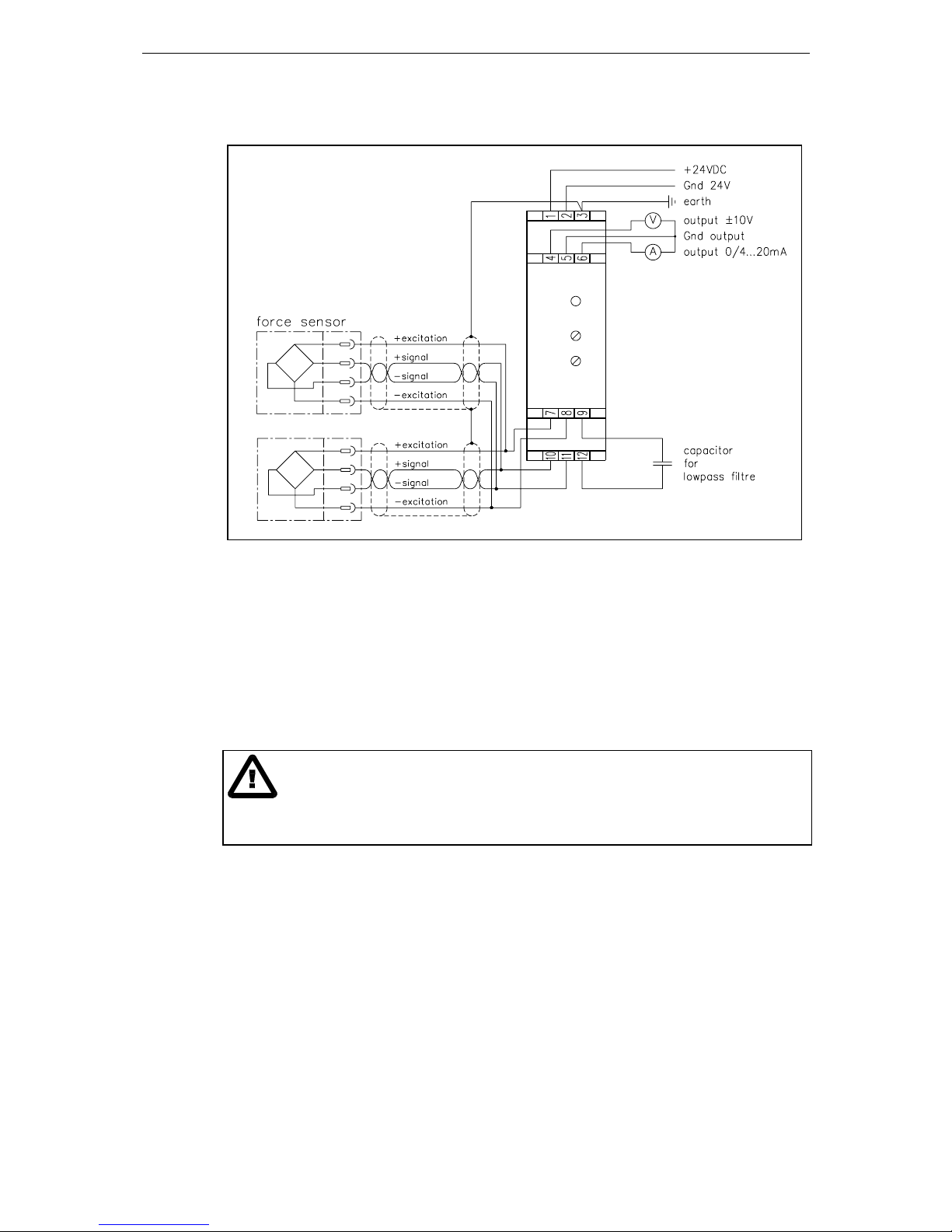
The lowpass filter is effective to both the tension- and the current output. The lower the
cut-off frequency, the more sluggish the output signal will be. The configuration is made
by connecting a non-polarized capacitor to the terminals 9 and 12 (refer to fig. 4). The
capacitor will be determined referring to the following formula resp. list:
Cut-off frequency
[Hz] Capacitor [µF]
1 10
C = 10 / F 2 5
5 2
10 1
C: Capacity [µF] 20 0.5
F: Cut-off frequency [Hz] 50 0.2
100 0.1
200 0.05
500 0.02
1000 0.01
Notice
You must not use electrolytic capacitors because positive and negative signals are
appearing! They would damage the electrolytic capacitor.
7.4 Calibrating the measuring amplifier
• Connect gauge to the tension- resp. current output.
• Connect the first force sensor
• Check, if a positive output signal is appearing when loading the sensor in measuring
direction. If not, exchange the two signal wires of the referring force sensor in the
terminal block (terminals 10 / 11).
• If used, connect the second force sensor.
• Check, if a positive output signal is appearing when loading the sensor in measuring
direction. If not, exchange the two
signal wires of the referring force
sensor in the terminal block (terminals
10 / 11).
• Insert material or a rope loosely to the
machine.
• Adjust the offset trimmer until the
output value is zero.
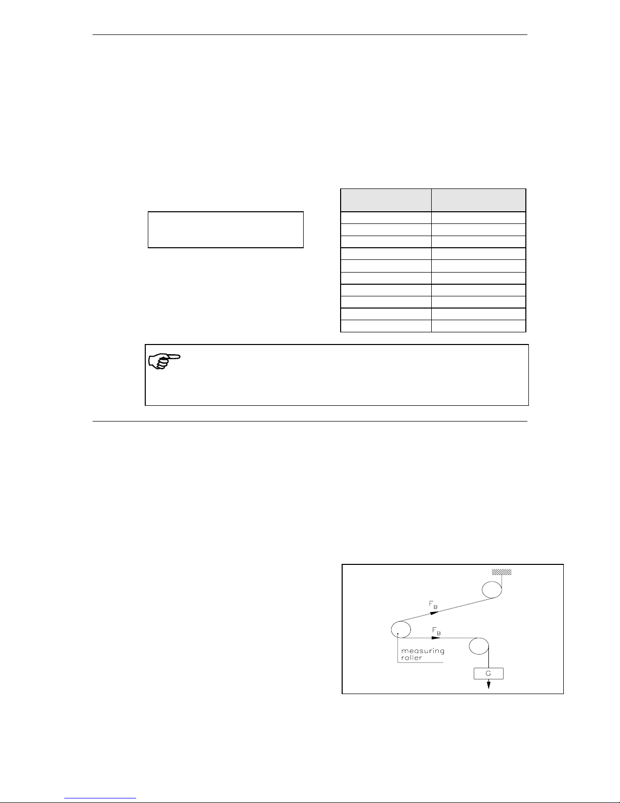
• Load material or rope with a defined
weight (fig. 8).
• Adjust the gain trimmer until the
output value shows the needed value
(for ex. 10V corresponding to 500N).
fig. 8: Calibrating the measuring amplifier

Operating manual EMGZ306A
11
8 Trouble shooting
Error Cause Corrective action
Output shows signal > 0
although material has no
tension
Offset setting is bad Re-adjust offset (refer to „7.4 Calibrating the
measuring amplifier“)
Current output is configured
for 4...20mA Change jumper setting if required
Output signal is not
stable although material
tension doesn’t change
Cut-off frequency too high Adjust cut-off frequency (refer to „7.3
Configuring the lowpass filter“)
Ground terminal of the output
isn’t 0V Connect Gnd terminal of the output (terminal 5)
with earth (terminal 3)
Output shows no
reaction, or LED don’t
light
Fuse blown Replace fuse on power supply
Power supply not correct Check / correct power supply
Measuring amplifier defect Contact FMS customer service
9 Technical Data
Sensor excitation 5VDC max. 30mA high precision (option 10VDC)
Gain factor range 500...5000
Offset range ±9mV
Temperature drift offset < 0.01% / K [0.006% / °F]
Linearity error < 0.1%
Tension output ±10V min. 1kΩ
Current output 0/4...20mA max. 500Ω
Lowpass cut-off frequency adjustable, ca. 1...1000Hz
Power supply 24VDC (18...36VDC) max. 0.1A
Power consumption max. 2.5W
Temperature range –10...+60°C [14...140°F]
Protection class IP20

Operating manual EMGZ306A
12
FMS Force Measuring Systems AG
Aspstrasse 6
8154 Oberglatt (Switzerland)
Tel. 0041 44 852 80 80
Fax 0041 44 850 60 06
info@fms-technology.com
www.fms-technology.com
FMS USA, Inc.
925 East Rand Road Suite 207
Arlington Heights, IL 60004 (USA)
Tel. 847 392 7872
Fax 847 392 7873
fmsusa@fms-technology.com
FMS (UK)
Highfield, Atch Lench Road
Church Lench
Evesham WR11 4UG (Great Britain)
Tel. 021-51085998
Fax 01386 871021
This manual suits for next models
1
Table of contents
Other FMS Amplifier manuals