FMS EMGZ470A.W User manual

Operating Manual
EMGZ470A.W / EMGZ472A.W
EMGZ470A.W.D / EMGZ472A.W.D
Digital microprocessor controlled Tension Measuring
Amplifier with integrated PROFIBUS interface
Operating Manual Version 2.3 04/2007 ff
Firmware Version from 1.04 08/2006
GSD Version 1.03 05/02
This operating manual is also available in German.
Please contact your local representative.
Diese Bedienungsanleitung ist auch in Deutsch erhältlich.
Bitte kontaktieren Sie Ihren nächstgelegenen FMS Vertreter.
© by FMS Force Measuring Systems AG, CH-8154 Oberglatt – All rights reserved.

Operating Manual EMGZ470A/472A
2
1Safety Instructions
1.1 Warnings
a) High danger of health injury or loss of life
Danger
This symbol refers to high risk for persons to get health injury or loss of life. This
warning has to be followed strictly.
b) Risk of damage of machines
Caution
This symbol refers to information, that, if ignored, could cause heavy mechanical
damage. This warning has to be followed absolutely.
c) Note for proper function
Note
This symbol refers to important information about proper use. If not followed,
malfunction can be the result.
1.2 List of Safety Instructions
The functionality of the Tension Measuring Amplifier is only guaranteed, if the
application and component recommendations are followed. In case of other
arrangement, heavy malfunction can be the result. Therefore, the installation
instructions on the following pages must strictly be followed.
Local installation regulations are to preserve safety of electric equipment. They are
not taken into consideration by this operating manual. However, they have to be
strictly followed.
Inadequate earth ground connection may cause electric shocks to persons,
malfunction of the total system or damage of the measuring amplifier! It is vital to
ensure a good earth ground connection.
Improper handling may damage the fragile electronic equipment! Don’t use rough
tools such as screwdrivers or pliers! Operators handling the processor board must
wear a well earthed bracelet in order to discharge static electricity.

Operating Manual EMGZ470A/472A
3
Table of Contents
1Safety Instructions ....................................................................................2
1.1 Warnings 2
1.2 List of Safety Instructions 2
2Definitions..................................................................................................4
3System Components..................................................................................4
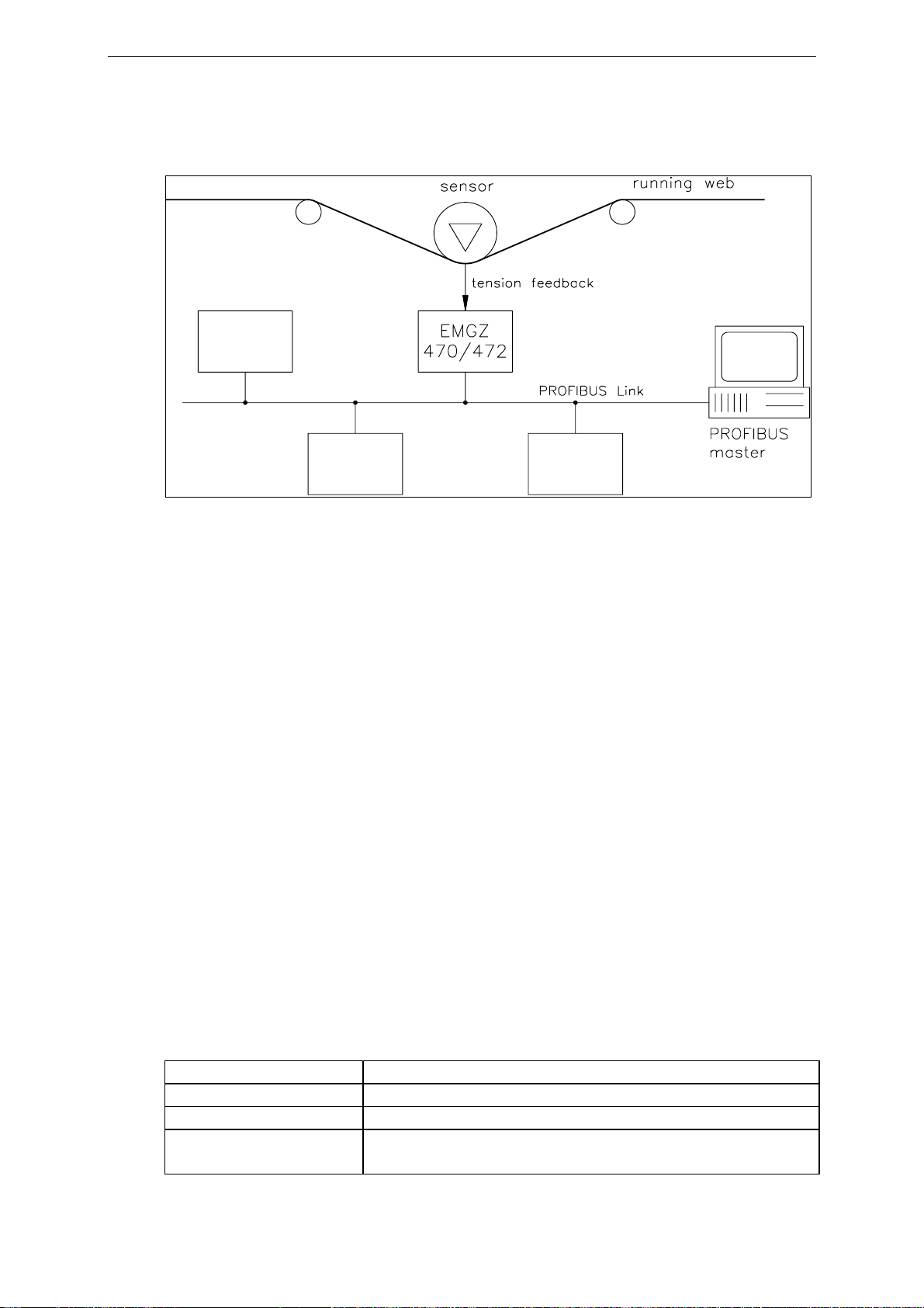
4System Description....................................................................................5
4.1 Functional Description 5
4.2 Force Sensor 5
4.3 Electronic Unit EMGZ470A.W/472A.W 5
4.4 Block Diagram 6
5Quick Installation Guide..........................................................................7
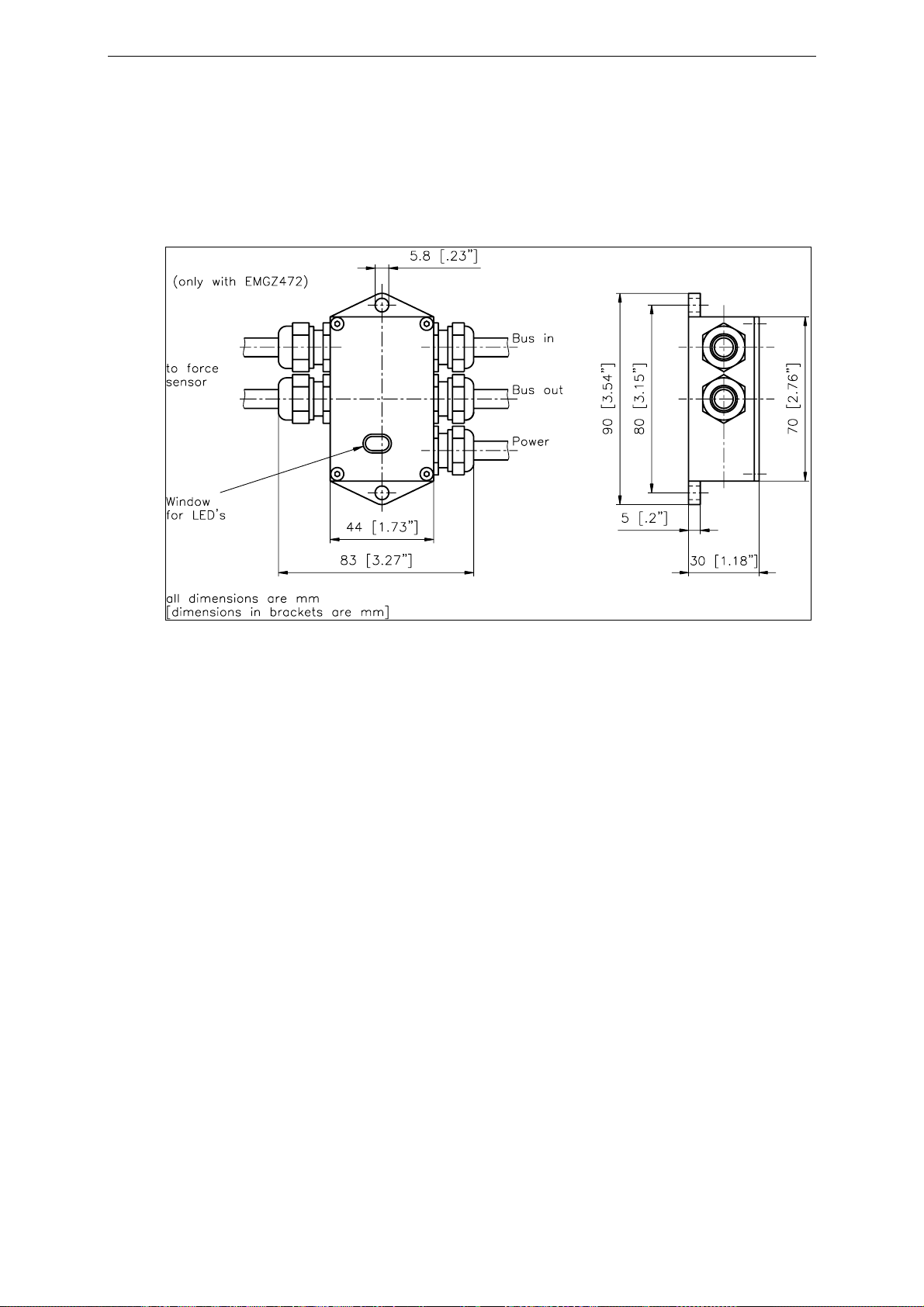
6Dimensions.................................................................................................8
6.1 Dimensions of Offset Version (EMGZ470A.W) 8
6.2 Dimensions Double-Channel Version (EMGZ470/472A.W.D) 9
7Installation and Wiring ..........................................................................10
7.1 Mounting the Force Sensors 10
7.2 Mounting of the Measuring Amplifier 10
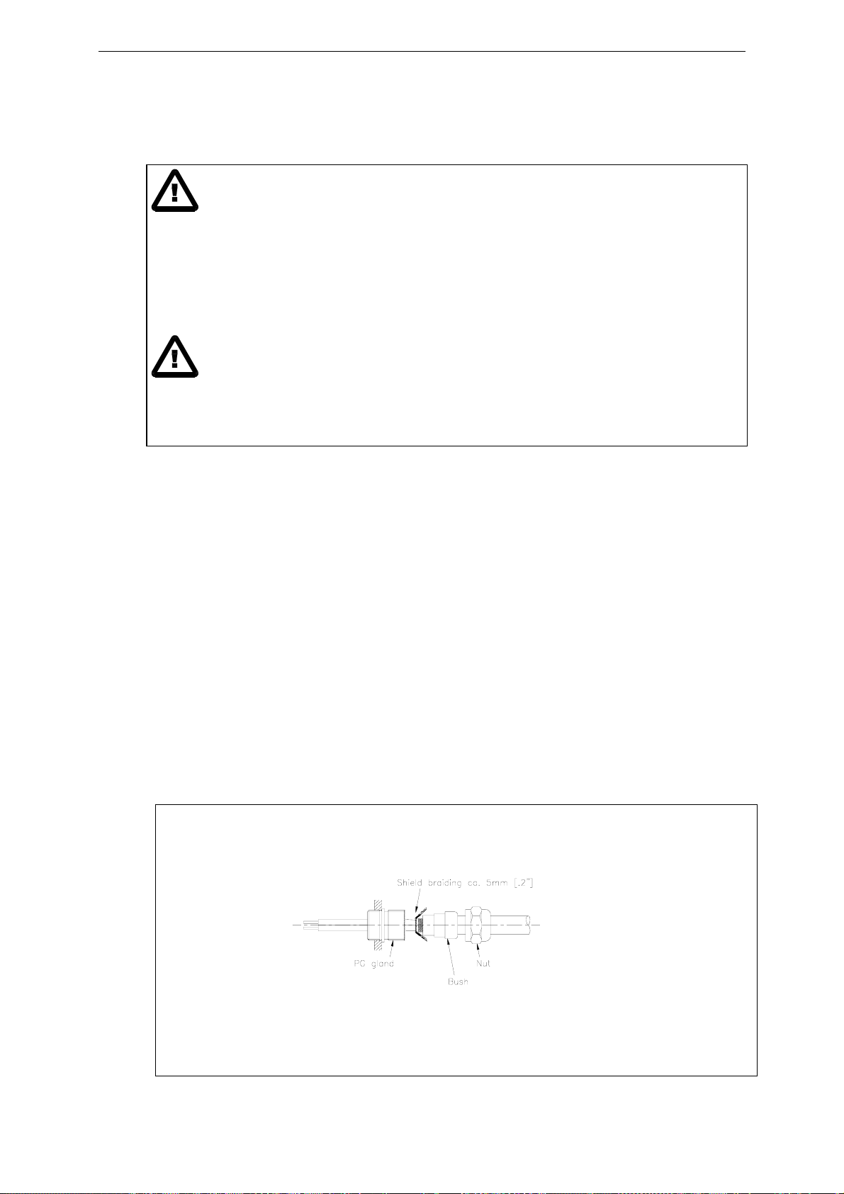
7.3 Wiring from Measuring Amplifier to Force Sensor 10
7.4 Wiring of Power Supply and PROFIBUS Data Cable 11
7.5 Wiring Diagram 12
7.6 Setting the PROFIBUS Address 13
8PROFIBUS Interface Description.........................................................14
8.1 GSD File 14
8.2 EMGZ470A.W/472A.W DP Slave Functional Description 14
8.3 Initial Parameters 14
8.4 Configuration 15
8.5 Process Data 16
9Calibrating the Measuring Amplifier ...................................................18
9.1 Simulating Method, Calibration within the PLC 18
9.2 Simulating Method, Calibration using Initial Parameters 19
9.3 Simulating Method, Calibration using Control Byte (Module 1 only) 19
9.4 Mathematical Method (Module 1 only) 20
9.5 Configuring the Lowpass Filter 21
10 Trouble Shooting.....................................................................................22
11 Technical Data EMGZ470A.W/472A.W...............................................23

Operating Manual EMGZ470A/472A
4
2Definitions
Offset: Correction value for compensation of the zero point difference. The offset
adjustment ensured that a force of 0N will generate a signal of 0V exactly.
Gain: Amplification factor for the measuring signal. Use of proper value will set the
measuring range of the sensor exactly corresponding to the signal output range.
Strain gauge: Electronic component that changes its resistance when it is extended.
Strain gauges are used in the FMS force sensors to gather the feedback value.
3System Components
The EMGZ470A.W/472A.W consists of the following components (refer also to fig.
1):
Force sensors
•For mechanical/electrical conversion of the tension force
•Force measuring bearing
•Force measuring roller
•Force measuring journal
•Force measuring bearing block
Electronic unit EMGZ470A.W/472A.W
•EMGZ470A.W: For supplying one force sensor and amplifying the mV signal
•EMGZ472A.W: For supplying two force sensors and amplifying the mV signal
•EMGZ470A.W.D.W/472A.D.W: For supplying one or two double range force
sensors and amplifying the mV signals
•With intergrated PROFIBUS interface for operation and parametrization
•Operates as PROFIBUS DP slave according to EN 50170
•For wall mounting, set off of force sensor (EMGZ470A.W.W)
PROFIBUS master computer
•For operation of the electronic unit EMGZ470A.W/472AW
•Operates as PROFIBUS DP master according to EN 50170
•Any master computer or PLC suitable
(Italic text indicates a variant or an option)

Operating Manual EMGZ470A/472A
5
4System Description
fig. 1: Basic structure EMGZ470A.W/472A.W Tension Measuring Amplifier E470001e
4.1 Functional Description
The force sensor measures the tension force in the material and transmits the value as
a mV signal to the electronic unit. The electronic unit amplifies the mV signal
depending on configuration. The resulting feedback value can be read by the
PROFIBUS master. The application dependent calculations will be done by the
PROFIBUS master.
4.2 Force Sensor
The force sensors use the flexion beam principle. The flexion is measured by strain
gauges and transmitted to the electronic unit as mV signal. Power supply exerts
influence to the strain gauges Wheatstone Bridge. The force sensors are therefore
supplied from the electronic unit with a very accurate power supply.
4.3 Electronic Unit EMGZ470A.W/472A.W
Common
The electronic unit contains a microprocessor to handle all calculations and
communications, the highly accurate sensor power supply and the signal amplifier for
the measuring value. In addition, a PROFIBUS interface is integrated to the electronic
unit.
The EMGZ470A.W.D /472A.W.D has the complete electronic unit twice to evaluate
two measuring ranges.
EMGZ470A.W for 1 force sensor
EMGZ472A.W for 2 force sensors (sum signal)
EMGZ470A.W.D for 1 double range force sensor
EMGZ472A.W.D for 2 double range force sensors
(1 sum signal per measuring range)

Operating Manual EMGZ470A/472A
6
Strain gauge amplifier
The strain gauge amplifier provides the highly accurate 4V power supply. A highly
accurate, fixed difference amplifier rises the mV signal up to 10V. This signal will be
fed to the A/D converter. The microprocessor then calculates a standardized signal
from the digitized measuring value, which is fed to the PROFIBUS interface.
PROFIBUS interface
The EMGZ470A.W/472A.W operates as PROFIBUS DP slave according to EN
50170. All settings and the entire communication is done by the integrated
PROFIBUS interface.
4.4 Block Diagram
fig. 2 E470002e

Operating Manual EMGZ470A/472A
7
5Quick Installation Guide
•Check all your requirements such as: Configuration of the PROFIBUS interface
(address number, data format, required PROFIBUS cycle time, termination) and
calibration mode (ref. to „9. Calibrating the measuring amplifier“) etc..
•Draw your final wiring diagram according to the FMS recomendations (refer to
„7.5 Wiring diagram)
•Install and wire all your components (refer to „7. Installation and wiring“)
•Make settings in the PROFIBUS master computer (DP master) (ref. to
„8. PROFIBUS Interface Description“)
•Put measuring amplifier into operation and calibrate it by PROFIBUS (refer to
„9. Calibrating the measuring amplifier“)
•Turn system on; proceed with a test run with low speed
•If required, activate additional application-specific functions of the PROFIBUS
master computer (DP master)
Note
If a real-time control loop is implemented with the PROFIBUS, you must ensure
that the application-specific PROFIBUS protocol is timewise short enough to
provide sufficient control dynamics.

Operating Manual EMGZ470A/472A
8
6Dimensions
6.1 Dimensions of Offset Version (EMGZ470A.W)
fig. 4: Outline drawing EMGZ470A.W / 472A.W E470004us

Operating Manual EMGZ470A/472A
9
6.2 Dimensions Double-Channel Version (EMGZ470/472A.W.D)
fig. 5: Outline drawing EMGZ470.D.W / 472.D.W E472001e

Operating Manual EMGZ470A/472A
10
7Installation and Wiring
Caution
The functionality of the Tension Measuring Amplifier is only guaranteed, if the
application and components recommendations are followed. In case of other
arrangements, heavy malfunction can be the result. Therefore, the installation
instructions on the following pages must strictly be followed.
Caution
Local installation regulations are to preserve safety of electric equipment. They are not
taken into consideration by this operating manual. However, they have to be strictly
followed.
7.1 Mounting the Force Sensors
Mounting of the force sensors is done referring to the FMS installation manual which
is delivered together with the force sensors.
7.2 Mounting of the Measuring Amplifier
The measuring amplifier is mounted directly to the force sensor using the FMS
standard plug (fig. 3). When using the offset version (EMGZ470A.W. /
EMGZ472A.W) the housing is mounted to the machine frame close to the force sensor
(fig. 4 and 5).
7.3 Wiring from Measuring Amplifier to Force Sensor
EMGZ470A.W / EMGZ472A.W
The cables are bared as shown in fig. 6 and then soldered to the terminals on the pc
board according to wiring diagram (fig. 8 and 9).
fig 6: Connecting the shield E470009e

Operating Manual EMGZ470A/472A
11
Note
Modifications in the wiring by the customer are not recommended. The connection of
the shield must be done as indicated in our wiring diagram. The shield should be
connected only to the measuring amplifier. On the „force sensor side“, the shield
should stay open. Other arrangements may cause ground/earth loops which may
interfere with the measuring signal. Malfunction can be the result.
7.4 Wiring of Power Supply and PROFIBUS Data Cable
Wiring of the power supply
The wiring of the power supply (24 VDC) to the terminals in the housing is covered in
the wiring diagram.
Caution
Inadequate earth ground connections may cause electric shock to persons, malfunction
of the total system or damage of the measuring amplifier! It is vital to ensure a good
earth ground connection.
Caution
Improper handling of the amplifier unit may damage the fragile electronic circuitry.
Don’t use rough tools such as screwdrivers or pliers! Handling in the electronic unit
must always take place with the operator using well earthed antistatic bracelets. This
will discharge static electricity of your body before touching the electronic unit!
Wiring of the PROFIBUS cables
The standardized PROFIBUS cable type A
(STP 2x0.342) [AWG 22] has to be used for
the PROFIBUS data cable. The cables are
bared referring to fig. 7 and connected to
the terminals according to the wiring
diagram.
Caution
The shield of the PROFIBUS cable is only grounded if the shield is connected with the
PG gland.
fig. 7: Preparation of the PROFIBUS
cables E470010e

Operating Manual EMGZ470A/472A
12
Termination
If both cables are connected (Bus-in and Bus-out), the two termination jumpers have to be
removed (fig. 8 and 9).
If only one cable is connected (Bus-in), both termination jumpers have to be set (fig. 8 and 9).
Note
The PROFIBUS network has to be terminated properly. Otherwise the installation
cannot be put into operation. Please ensured that only the last device of the
PROFIBUS chain is terminated.
7.5 Wiring Diagram
fig. 8: Wiring diagram EMGZ470A.W/472A.W E470006e
fig. 9: Wiring diagram EMGZ470A.W.D/472A.D E472002e

Operating Manual EMGZ470A/472A
13
7.6 Setting the PROFIBUS Address
The measuring amplifier requires a unique
PROFIBUS address which distinguish the
device definitely in the whole PROFIBUS
network. No other PROFIBUS device in the
same network may use the same address.
The address has to be between 0...125.
The PROFIBUS address is set with the DIP
switch (fig. 9). Please refer to the table
below for the setting. After switching the
measuring amplifier off and on, the new
address becomes valid.
Ad
r DIP switch Ad
r DIP switch Ad
r DIP switch Ad
r DIP switch Adr DIP switch
0 0000 0000 25 0001 1001 50 0011 0010 75 0100 1011 100 0110 0100
1 0000 0001 26 0001 1010 51 0011 0011 76 0100 1100 101 0110 0101
2 0000 0010 27 0001 1011 52 0011 0100 77 0100 1101 102 0110 0110
3 0000 0011 28 0001 1100 53 0011 0101 78 0100 1110 103 0110 0111
4 0000 0100 29 0001 1101 54 0011 0110 79 0100 1111 104 0110 1000
5 0000 0101 30 0001 1110 55 0011 0111 80 0101 0000 105 0110 1001
6 0000 0110 31 0001 1111 56 0011 1000 81 0101 0001 106 0110 1010
7 0000 0111 32 0010 0000 57 0011 1001 82 0101 0010 107 0110 1011
8 0000 1000 33 0010 0001 58 0011 1010 83 0101 0011 108 0110 1100
9 0000 1001 34 0010 0010 59 0011 1011 84 0101 0100 109 0110 1101
10 0000 1010 35 0010 0011 60 0011 1100 85 0101 0101 110 0110 1110
11 0000 1011 36 0010 0100 61 0011 1101 86 0101 0110 111 0110 1111
12 0000 1100 37 0010 0101 62 0011 1110 87 0101 0111 112 0111 0000
13 0000 1101 38 0010 0110 63 0011 1111 88 0101 1000 113 0111 0001
14 0000 1110 39 0010 0111 64 0100 0000 89 0101 1001 114 0111 0010
15 0000 1111 40 0010 1000 65 0100 0001 90 0101 1010 115 0111 0011
16 0001 0000 41 0010 1001 66 0100 0010 91 0101 1011 116 0111 0100
17 0001 0001 42 0010 1010 67 0100 0011 92 0101 1100 117 0111 0101
18 0001 0010 43 0010 1011 68 0100 0100 93 0101 1101 118 0111 0110
19 0001 0011 44 0010 1100 69 0100 0101 94 0101 1110 119 0111 0111
20 0001 0100 45 0010 1101 70 0100 0110 95 0101 1111 120 0111 1000
21 0001 0101 46 0010 1110 71 0100 0111 96 0110 0000 121 0111 1001
22 0001 0110 47 0010 1111 72 0100 1000 97 0110 0001 122 0111 1010
23 0001 0111 48 0011 0000 73 0100 1001 98 0110 0010 123 0111 1011
24 0001 1000 49 0011 0001 74 0100 1010 99 0110 0011 124 0111 1100
125 0111 1101
fig. 10: Codification of the PROFIBUS
address (Example with address 54)
E470007e

Operating Manual EMGZ470A/472A
14
8PROFIBUS Interface Description
8.1 GSD File
The PROFIBUS DP master has to know which devices are connected to the
PROFIBUS network. For this purpose the GSD file is required. The GSD file for the
EMGZ470A.W / 472A.W measuring amplifier can be taken from the following
internet address:
http://www.fms-technology.com/gsd
The GSD file can also be supplied on a CD-ROM on request. In this case please
contact FMS customer service.
Read the GSD file into the PROFIBUS DP master
How to read in the GSD file into the control system (DP master) depends on the used
control system. For further information, refer to the documentation of the control
system.
Note
The GSD file version must match with the firmware version of the measuring
amplifier. Otherwise set-up problems may occur. Version numbers of firmware and
GSD file are indicated on the cover page of this operating manual.
8.2 EMGZ470A.W/472A.W DP Slave Functional Description
The measuring amplifier EMGZ470A.W/472A supports the PROFIBUS DP protocol
according to EN 50170. Hereby the measuring amplifier operates as DP slave and the
control system as DP master. Several parameters have to be set and met by the control
system.
8.3 Initial Parameters
Initialisation parameters are sent from the control system to the measuring amplifier
when the initialisation process is started. Normally this parameter set has been pre-
programmed with fixed values for a given machine.
The first bytes in the parameter telegram are specified in the EN 50170 standard. An
user segment of 6 bytes is defined for the measuring amplifier.
Byte Use Value Meaning
0 Initial parameter 0
1 (Remain Offset unchanged)
Find Offset
1 User Gain Reference,
High Byte 0
≠0 (Remain Gain unchanged)
Calibrate Gain: Tell the measuring amplifier the
2 User Gain Reference,
Low Byte force value which corresponds to the actual load.
3 Lowpass filter 0
≠0 Filter OFF
Filter ON (ref. to „9.5 Configuring the Lowpass
Filter“)
Byte 0 (Find Offset) has priority against Byte 1 + 2 (Calibrate Gain).

Operating Manual EMGZ470A/472A
15
8.4 Configuration
The configuration defines the amount of process data (byte and word) that is sent
during the cyclic communication from the control system to the measuring amplifier
and from the measuring amplifier to the control system. Normally a fixed value is set
with the programming tool of the control system.
To ensure maximum flexibility, several modules (telegram structure) can be chosen.
In a single measuring amplifier only one module can be set active at a time. The
terminology and structure of the modules base on the profiles described in the variable
speed drives section of the PROFIBUS user organization.
Module 1: Full control
3 bytes are transmitted from the control system to the measuring amplifier and vice
versa in each data cycle.
Byte 0 Byte 1 Byte 2
Request telegram
(Master →Slave) Control byte
(STB) Main reference value
Higher Byte Main reference value
Lower Byte
Response telegram
(Slave →Master) Status Byte
Status Main feedback value
Higher Byte Main feedback value
Lower Byte
Module 2: Feedback value with status
The control system sends periodically an empty telegram. The measuring amplifier
answers with the actual feedback value and with a status byte which indicates the
quality of the feedback value. This configuration can be used after offset and gain
adjustment has been completed. It can only be used if no process parameters of the
measuring amplifier are read or modified, or if the controller is not running the
evaluation the feedback value.
Byte 0 Byte 1 Byte 2
Request telegram
(Master →Slave) empty
Response telegram
(Slave →Master) Status Byte
Status Main feedback value
Higher Byte Main feedback value
Lower Byte
Module 2a: Feedback value with status
It’s identical with module 2 but the length of the response telegram is 4 Byte. The higher
status byte is not used and therefore contains all 0.
Byte 0 Byte 1 Byte 2 Byte 3
Request telegram
(Master →Slave) empty
Response telegram
(Slave →Master) 00000000
Higher Byte Status Byte
Lower Byte Main
feedback
value
Higher Byte
Main
feedback
value
Lower Byte

Operating Manual EMGZ470A/472A
16
8.5 Process Data
The amount of process data specified in the configuration is transmitted periodically.
It is distinguished between value, main feedback value, control byte and status byte.
Control byte (STB)
The control byte transmits the required command to the measuring amplifier. (Module
1 only)
Master →Slave
STB HSW
Bit # 7......0
Value Meaning Remarks
00h Default Normal operating mode
09h Read Device Type
21h Read User Offset
23h Write User Offset HSW = User Offset to be written
25h Find User Offset Measuring value will be set to zero
29h Read User Gain
2Bh Write User Gain HSW = User Gain to be written
2Dh Calibrate User Gain HSW = Force value which corresponds to the
actual material tension
F9h Read Firmware
Version
Main reference value (HSW)
The main reference value transmits the actual parameter value. (Module 1 only)
Master →Slave
STB
HSW
Bit # 15......0
The main reference value is a 16 bit word (range ±32767). The high byte is
transmitted before the low byte.
We recommend to set Offset and Gain such that loading the sensor at nominal force
will result in a feedback value of 10000 (default). (ref. to „9. Calibrating the
measuring amplifier“)

Operating Manual EMGZ470A/472A
17
Status byte (Status)
The status byte indicates the status of the measuring amplifier.
Slave →Master
Status HIW
Bit # 7......0
Value Meaning Remarks
00h Ok Acquiring of measuring value ok
02h Overflow The allowed measuring range is exceeded
04h Error An error appeared during acquiring of the measuring
value
06h Overload The sensor power source is overload
09h Read Device Type EMGZ470: HIW = 1 resp. EMGZ472: HIW = 2
21h User Offset read HIW = User Offset read
23h User Offset written HIW = User-Offset written
25h User Offset found HIW = User Offset found
29h User Gain read HIW = User Gain read
2Bh User Gain written HIW = User Gain written
2Dh User Gain
calibrated HIW = User Gain calculated
F9h Firmware Version HIW = main version (high byte) + sub version (low
byte)
Main actual value (HIW)
The main feedback value transmits the actual measuring value.
Slave →Master
Status
HIW
Bit # 15......0
The main feedback value is a 16 bit word (range ±32767) which transmits the
processed measuring value of the measuring amplifier. The high byte is transmitted
before the low byte

Operating Manual EMGZ470A/472A
18
9Calibrating the Measuring Amplifier
To get correct measuring values, offset and gain have to be determinate when putting
the device into operation. There are several methods for this task:
Method Use with Advantage
Simulating method
calibration within the PLC Module 1+2 No settings required for the
measuring amplifier
Simulating method
calibration using initial
parameters
Module 1+2 Can be done without programming
Simulating method
calibration using control byte Module 1 Highest flexibility
Mathematical method Module 1 Less accurate than simulating
method
9.1 Simulating Method, Calibration within the PLC
The following instructions are referring to
a setup and calibration inside the machine.
The material tension will be simulated by
a weight (fig. 10).
Offset and Gain calibration is done in the
PLC or the master computer.
•Insert material or a rope loosely to the
machine.
•The offset corresponds to the actually
transmitted main feedback value
(HIW): HIWoffset=
•Load material or rope with a defined
weight (fig. 10)
•The gain factor is now calculated from
the actually transmitted main feedback
value (HIW):
()
offsetHIWF F
gain
alNo
Calib
−⋅
⋅
=
min
10000
•The determined values for gain and offset are used by the control system to
calculate the actual material tension in [N] from the main feedback value:
()
offsetHIW
F
gainF alNo
Beff −⋅⋅= 10000
min
Definition of symbols:
FCalib applied calibration load [N or lbs] (refer to fig. 11)
FNominal nominal force of sensor [N or lbs]
FBeff actual material tension [N or lbs]
HIW main feedback value
fig. 10: Calibrating the measuring
amplifier C431011e

Operating Manual EMGZ470A/472A
19
9.2 Simulating Method, Calibration using Initial Parameters
The following instructions are referring to a setup and calibration inside the machine.
The material tension will be simulated by a weight (fig. 10).
Offset and Gain calibration is done in the measuring amplifier using the initial
parameter (ref. also to „8.3 Initial Parameter“).
•Insert material or a rope loosely to the machine.
•Set initial parameter byte 0 to „1“. The measuring amplifier calculates
automatically the new offset value.
•Reset initial parameter byte 0 to „0“.
•Load material or rope with a defined weight (fig. 10)
•Set initial parameter byte 1+2 to a measuring value corresponding to the applied
weight (ref. to „8.3 Initial Parameter“). The measuring amplifier calculates
automatically the new gain value.
•Reset initial parameter byte 1+2 to „0“.
•Offset and Gain are now fail safe stored in the measuring amplifier.
Note
The main feedback value (HIW) must also be capable to indicate correctly overload
values. Therefore the calibration must be done in a way that the HIW range (±32767)
is not fully exhausted at nominal load. We recommend to set Offset and Gain so that
loading the sensor at nominal force will give a feedback value of 10000.
9.3 Simulating Method, Calibration using Control Byte (Module
1 only)
The following instructions refer to a setup and calibration inside the machine. The
material tension will be simulated by a weight (fig. 10).
Offset and Gain calibration is done in the measuring amplifier using the control byte
and the main reference value (module 1 only; ref. also to „8.5 Process Data“).
•Insert material or a rope loosely to the machine.
•Set control byte of a request telegram to „25h“. The measuring amplifier calculates
automatically the new offset value. The new offset value is transmitted in the
corresponding response telegram (ref. to „8.5 Process Data“).
•Load material or rope with a defined weight (fig. 10)
•Enter control byte of a request telegram to „2Dh“ and the main reference value
(HSW) to a measuring value corresponding to the applied weight (ref. to „8.3
Initial Parameter“). The measuring amplifier calculates automatically the new gain
value. The new gain value is transmitted in the corresponding response telegram
(ref. to „8.5 Process Data“).
•Offset and Gain are now fail safe stored in the measuring amplifier.
•If required, you can switch now to module 2 (feedback with status) (ref. to „8.4
Configuration“).

Operating Manual EMGZ470A/472A
20
9.4 Mathematical Method (Module 1 only)
If the material tension cannot be simulated, calibration has to be done by calculation.
This way of calibrating is less accurate because the exact angles are often unknown. In
addition the actual mounting conditions, which usually deviate from the ideal world,
can seldom taken into account.
fig. 11: Force vectors in the FMS force measuring bearing C431012e
•Offset adjustment has to be done as described under „Simulating method,
calibration using control byte“.
•The Gain value will be calculated by the following formula:
Definition of symbols:
αangle between vertical and
measuring web axis FBmaterial tension
βangle between vertical and FMF
Groller weight
γwrap angle of material FMmeasuring force resulting from
FB
γ1entry angle of material FMef
feffective measuring force
γ2exit angle of material n number of force sensors
δAngle between measuring web axis
and FM
•Enter control byte of a request telegram to „2Bh“ and the main reference value
(HSW) to the calculated gain value (ref. to „8.5 Process Data“). The measuring
amplifier stores the gain value. The new gain value is transmitted in the
corresponding response telegram (ref. to „8.5 Process Data“).
•Offset and Gain are now fail safe stored in the measuring amplifier.
()
n
GainFactor ⋅⋅
=2/sinsin 1
γδ
This manual suits for next models
3
Table of contents
Other FMS Amplifier manuals