Operating Manual EMGZ621A
3
Table of Contents
1Safety Instructions ....................................................................................2
1.1 Description conditions 2
1.2 List of safety instructions 2
2Definitions..................................................................................................4
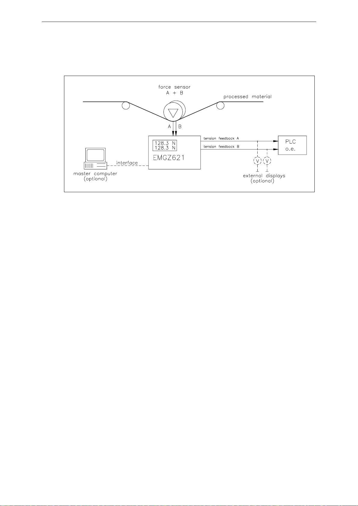
3System Components..................................................................................4
4System Description....................................................................................5
4.1 Functional Description 5
4.2 Force Sensors 5
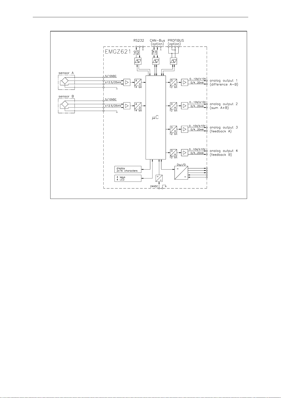
4.3 Electronic Units EMGZ621A 6
5Quick Installation Guide..........................................................................7
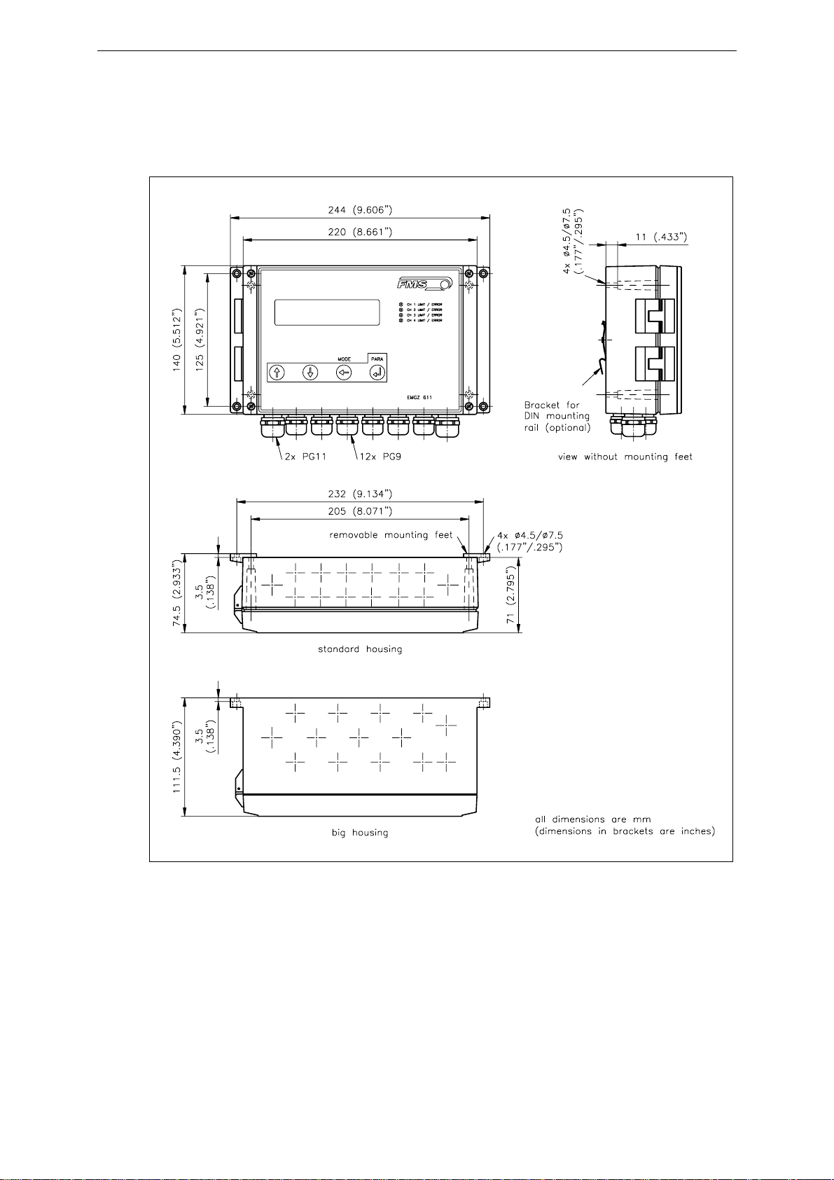
6Dimensions.................................................................................................8
7Installation and Wiring ............................................................................9
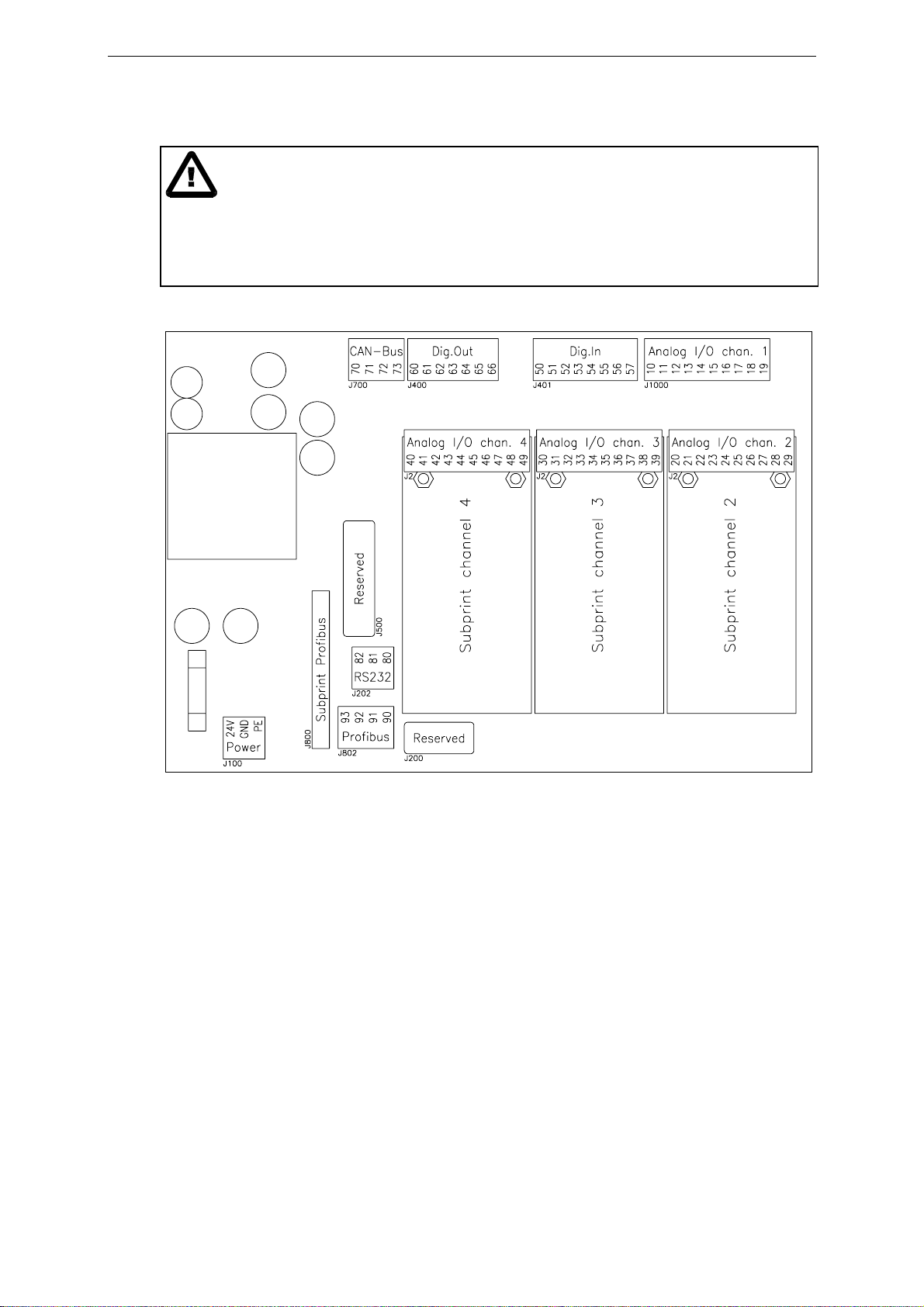
7.1 Mounting the Electronic Unit 9
7.2 Wiring Diagram 11
7.3 Mounting the Force Sensors 12
8Operating .................................................................................................13
8.1 View of the Operating Panel 13
8.2 Configuring the Electronic Unit 14
8.3 Calibrating the Measuring Amplifier 15
8.4 Additional Settings 17
9Parametrization.......................................................................................18
9.1 Schematic Diagram of Parametrization 18
9.2 List of the system parameters 19
9.3 List of the parameters EMGZ621A 19
9.4 Description of the system parameters 20
9.5 Description of the Parameters EMGZ621A 21
9.6 Service Mode 25
10 Serial Interface (RS232) .........................................................................26
11 PROFIBUS Interface Description.........................................................27
11.1 Wiring of the PROFIBUS Data Cable 27
11.2 Setting the PROFIBUS Address 28
12 PROFIBUS Interface Description.........................................................29
12.1 GSD File 29
12.2 EMGZ621A DP Slave Functional Description 29
12.3 Initial Parameters 29
12.4 Configuration 30
12.5 Function Code 30
13 Interface CAN-Bus..................................................................................31
14 Interface DeviceNet.................................................................................31
15 Technical Reference................................................................................32
15.1 Additional Setting Elements 32
15.2 Dip-switch for the Analogue Inputs / Outputs 33
15.3 Technical Data 37
16 Trouble Shooting.....................................................................................38