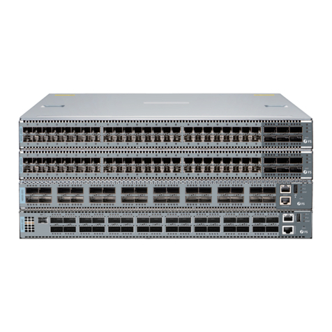
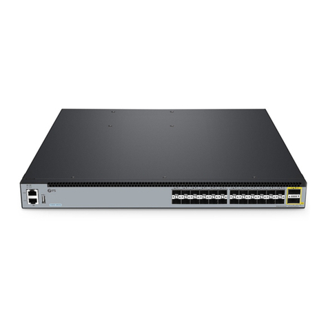
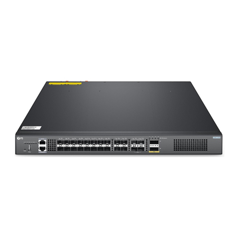
FS N5860 Series User manual

L3 DATA CENTER SWITCHES
N5860 and N8560 Series 10G/25G/100G Switches
Quick Start Guide V1.0
Status
N8560-64C
ID
Link
MGMT
CONSOLE
ACT
1F 2F 5F 6F 9F 10F13F14F17F18F21F22F25F26F29F30F33F34F37F38F41F42F45F46F49F50F53F54F57F58F61F62F
3F 4F 7F 8F 11F12F15F16F19F20F23F24F27F28F31F32F35F36F39F40F43F44F47F48F51F52F55F56F59F60F63F64F
1F 2F 3F 4F 5F 6F 7F 8F 9F 10F 11F 12F 13F14F15F16F17F18F19F20F 21F22F23F24F25F26F27F28F 29F30F31F 32F33F 34F35F 36F37F 38F 39F40F41F 42F 43F 44F 45F46F 47F 48F
100G
49F 50F 51F 52F 53F 54F 55F 56F
Status ID
N8560-48BC
1F 2F 3F 4F 5F 6F 7F 8F 9F 10F11F12F13F14F15F16F17F18F19F20F21F22F23F24F25F26F27F28F29F30F31F 32F33F34F35F 36F 37F38F39F40F41F42F43F44F45F46F 47F48F
100G
49F 50F 51F 52F 53F 54F 55F 56F
Status ID
N5860-48SC

Introduction
Thank you for choosing N5860 and N8560 Series 10G/25G/100G Switches. This guide is designed to
familiarize you with the layout of the switch and describes how to deploy the switch in your network.
Accessories
Grounding Cable x1Power Cord x2 Mounting Bracket x2 M4 Screw x14
M6 Screw x8 M6 Nut x8 Inner Rail x2Slide Rail x2
N5860-48SC/N8560-48BC
1F 2F 3F 4F 5F 6F 7F 8F 9F 10F11F12F13F14F15F16F17F18F19F20F21F22F23F24F25F26F27F28F29F30F31F32F33F34F35F36F37F38F39F40F41F42F43F44F45F46F47F48F
100G
49F 50F 51F 52F 53F 54F 55F 56F
Status ID
MGMT CONSOLE
1F 2F 3F 4F 5F 6F 7F 8F 9F 10F11F12F13F14F15F16F17F18F19F20F21F22F23F24F25F26F27F28F29F30F31F32F
SYS PSU FAN
Link ACT
ASSETTAG
N8560-32C
N5860-48SC
1F 2F 3F 4F 5F 6F 7F 8F 9F 10F11F12F13F14F15F16F17F18F19F20F21F22F23F24F25F26F27F28F29F30F31F32F33F34F35F36F37F38F39F40F41F42F43F44F45F46F47F48F
100G
49F 50F 51F 52F 53F 54F 55F 56F
Status ID
Status
N8560-64C
ID
Link MGMT
CONSOLE
ACT
1F 2F 5F 6F 9F 10F13F14F17F18F21F22F25F26F29F30F33F34F37F38F41F42F45F46F49F50F53F54F57F58F61F62F
3F 4F 7F 8F 11F12F15F16F19F20F23F24F27F28F31F32F35F36F39F40F43F44F47F48F51F52F55F56F59F60F63F64F
N8560-48BC
N8560-48BC
N5860-48SC
N8560-64C
N8560-32C

NOTE: The switches have dust plugs delivered with them. Keep the dust plugs properly
and use them to protect idle optical ports.
Grounding Cable x1Power Cord x2 Mounting Bracket x2 M4 Screw x12
M6 Screw x8 M6 Nut x8 Inner Rail x2Slide Rail x2
N8560-32C
Grounding Cable x1Power Cord x2 Mounting Bracket x2 M4 Screw x18
M6 Screw x8 M6 Nut x8 Inner Rail x2Slide Rail x2
N8560-64C

Hardware Overview
Front Panel Ports
Ports Description
SFP+
SFP28
QSFP28
SFP+ ports for 1/10G connection
SFP28 ports for 10/25G connection
QSFP28 ports for 40/100G connection
N5860-48SC
N8560-48BC
N8560-32C
N8560-64C
N5860-48SC
1F 2F 3F 4F 5F 6F 7F 8F 9F 10F 11F 12F 13F 14F 15F 16F 17F 18F 19F 20F 21F 22F 23F 24F 25F 26F 27F 28F 29F 30F 31F 32F 33F 34F 35F 36F 37F 38F 39F 40F 41F 42F 43F 44F 45F 46F 47F 48F
100G
49F 50F 51F 52F 53F 54F 55F 56F
Status ID
QSFP28SFP+
N8560-48BC
1F 2F 3F 4F 5F 6F 7F 8F 9F 10F 11F 12F 13F 14F 15F 16F 17F 18F 19F 20F 21F 22F 23F 24F 25F 26F 27F 28F 29F 30F 31F 32F 33F 34F 35F 36F 37F 38F 39F 40F 41F 42F 43F 44F 45F 46F 47F 48F
100G
49F 50F 51F 52F 53F 54F 55F 56F
Status ID
QSFP28SFP28
Status
N8560-64C
ID
Link MGMT
CONSOLE
ACT
1F 2F 5F 6F 9F 10F 13F 14F 17F 18F 21F 22F 25F 26F 29F 30F 33F 34F 37F 38F 41F 42F 45F 46F 49F 50F 53F 54F 57F 58F 61F 62F
3F 4F 7F 8F 11F 12F 15F 16F 19F 20F 23F 24F 27F 28F 31F 32F 35F 36F 39F 40F 43F 44F 47F 48F 51F 52F 55F 56F 59F 60F 63F 64F
MGMT USB
CONSOLE QSFP28
MGMTUSB
CONSOLE QSFP28
MGMTCONSOLE
1F 2F 3F 4F 5F 6F 7F 8F 9F 10F11F12F13F14F15F 16F 17F18F19F20F21F 22F 23F24F25F 26F 27F 28F 29F30F31F32F
SYS PSU FAN
Link ACT
ASSET TAG
N8560-32C

Back Panels
Ports Description
USB
MGMT
CONSOLE
A USB management port for software and conguration backup and oine
software upgrade
An Ethernet management port
An RJ45 console port for serial management
N5860-48SC
N8560-48BC
N8560-32C
N8560-64C
Fan Slots
Fan Slots
Power Supply
Power Supply
Grounding Point
Grounding PointASSET TAG
AFM-N48SC-FB
Status Status Status
Status
FUNC
ID
Link ACT
Status
AFM-N48SC-FB AFM-N48SC-FB AFM-N48SC-FB
PWR1
PWR2
1 2 3
4
MGMT
CONSOLE
AFM-N48BC-FB
Status Status Status
Status
FUNC
ID
Link ACT
Status
AFM-N48BC-FB AFM-N48BC-FB AFM-N48BC-FB
PWR1
PWR2
1 2 3
4
MGMT
CONSOLE
PSU1 FAN1 FAN2 FAN3 FAN4 FAN5 PSU2
AFM-N64C-FB AFM-N64C-FB AFM-N64C-FB
1 2
Status Status Status
3
PWR1
PWR2
ASSET TAG
Power Supply
Power Supply
Grounding Point
Grounding Point
Fan SlotsPower Supply
Power Supply
ASSET TAG
Fan SlotsPower Supply Power Supply

Ports Description
USB
MGMT
CONSOLE
A USB management port for software and conguration backup and oine
software upgrade
An Ethernet management port
An RJ45 console port for serial management
ESDESD port for wearing ESD wrist strap
Back Panel Ports
N5860-48SC
N8560-48BC
N8560-32C
CONSOLE
USB
MGMT
AFM-N48SC-FB
Status Status Status
Status
FUNC
ID
Link ACT
Status
AFM-N48SC-FB AFM-N48SC-FB AFM-N48SC-FB
PWR1
PWR2
1 2 3
4
MGMT
CONSOLE
AFM-N48BC-FB
Status Status Status
Status
FUNC
ID
Link ACT
Status
AFM-N48BC-FB AFM-N48BC-FB AFM-N48BC-FB
PWR1
PWR2
1 2 3
4
MGMT
CONSOLE
CONSOLE
USB
MGMT
Back Panel Button
N5860-48SC
FUNC
AFM-N48SC-FB
Status Status Status
Status
FUNC
ID
Link ACT
Status
AFM-N48SC-FB AFM-N48SC-FB AFM-N48SC-FB
PWR1
PWR2
1 2 3
4
MGMT
CONSOLE
PSU1 FAN1 FAN2 FAN3 FAN4 FAN5 PSU2
ESD

Status
N8560-64C
ID
Link MGMT
CONSOLE
ACT
1F 2F 5F 6F 9F 10F 13F 14F 17F 18F 21F 22F 25F 26F 29F 30F 33F 34F 37F 38F 41F 42F 45F 46F 49F 50F 53F 54F 57F 58F 61F 62F
3F 4F 7F 8F 11F 12F 15F 16F 19F 20F 23F 24F 27F 28F 31F 32F 35F 36F 39F 40F 43F 44F 47F 48F 51F 52F 55F 56F 59F 60F 63F 64F
Button Description
FUNCReserved function button
Front Panel LEDs
N5860-48SC
N8560-48BC
N5860-48SC
1F 2F 3F 4F 5F 6F 7F 8F 9F 10F 11F 12F 13F 14F 15F 16F 17F 18F 19F 20F 21F 22F 23F 24F 25F 26F 27F 28F 29F 30F 31F 32F 33F 34F 35F 36F 37F 38F 39F 40F 41F 42F 43F 44F 45F 46F 47F 48F
100G
49F 50F 51F 52F 53F 54F 55F 56F
Status ID
QSFP28SFP+
Satus/ID
N8560-48BC
1F 2F 3F 4F 5F 6F 7F 8F 9F 10F 11F 12F 13F 14F 15F 16F 17F 18F 19F 20F 21F 22F 23F 24F 25F 26F 27F 28F 29F 30F 31F 32F 33F 34F 35F 36F 37F 38F 39F 40F 41F 42F 43F 44F 45F 46F 47F 48F
100G
49F 50F 51F 52F 53F 54F 55F 56F
Status ID
QSFP28SFP28
Satus/ID
N8560-48BC
AFM-N48BC-FB
Status Status Status
Status
FUNC
ID
Link ACT
Status
AFM-N48BC-FB AFM-N48BC-FB AFM-N48BC-FB
PWR1
PWR2
1 2 3
4
MGMT
CONSOLE
FUNC
N8560-64C
Status
ID
QSFP28
Link/ACT

LEDs Status Description
Status
ID
Solid Red
Blinking Green
1. One of the power supply modules or fan modules fails.
The systemis powered o.
The systemis initializing.
Solid Green The system is operational.
Solid Yellow
O
Solid Blue
1. The temperature gets to the warning threshold.
Device location is disabled.
Device location is enabled.
Link/ACT
O
Link Solid Green
ACT Blinking Yellow
The port is not connected.
The port is connected at 10/100/1000Mbps.
The portis transmitting or receiving data.
2. For N8560-64C: Only 2 fans are in the position.
For N5860-48SC and N8560-48BC: Only 3 fans are in the position.
3. One of the dual power supplies is not connected with AC
power cord.
O
2. For N8560-64C: There are less than2 fans.
For N5860-48SC and N8560-48BC: There are less than3 fans.
3. The internal or partial temperature exceeds the warning
working temperature,and the switching service resets.
SFP+
O
Solid Green
Blinking Green
The SFP+ port is NOT connected.
The SFP+ port is connected at 1/10G.
The SFP+ port is transmitting or receiving data at 1/10G.
SFP28
O
Solid Green
Blinking Green
The SFP28 port is NOT connected.
The SFP28 port is connected at 10/25G.
The SFP28 port is transmitting or receiving data at 10/25G.
QSFP28
O
Solid Green
Blinking Green
The QSFP28 port is NOT connected.
The QSFP28 port is connected at 40/100G.
The QSFP28 port is transmitting or receiving data at 40/100G.
N8560-32C
LEDs Status Description
SYS
O
Blinking Green
Solid Red
Solid Green
The systemis powered o.
1. One of the power supply modules or fan modules fails.
2. There are less than4 fans.
3. The internal or partial temperature exceeds the warning
working temperature, and the switching service resets.
The systemis initializing.
The system is operational.
Solid Yellow
Solid Red
1. The temperature exceeds the threshold.
2. One of the fans is not in the position.
3. One of the dual power supplies is not connected with AC
power cord.
The power supply module is in an abnormal state.
PSU Solid Green
Solid Yellow
The power supply module is operational.
One of the dual power supplies is not connected with AC
power cord.
FAN
Solid Green
Solid Red
Solid Yellow
The fan is operational.
1. The fan is in an abnormal state.
2. There are less than 4 fans.
Only 4 fans are in the position.
SYS
QSFP28Link/ACT
FAN
PSU
MGMTCONSOLE
1F 2F 3F 4F 5F 6F 7F 8F 9F 10F11F12F13F14F15F 16F 17F18F19F20F21F 22F 23F24F25F 26F 27F 28F 29F30F31F32F
SYS PSU FAN
Link ACT
ASSET TAG
N8560-32C

Back Panel LEDs
N5860-48SC
N8560-48BC
N8560-32C
Fan Status
Fan Status Status
StatusPower Supply Status Power Supply Status
Power Supply Status
ID
AFM-N48SC-FB
Status Status Status
Status
FUNC
ID
Link ACT
Status
AFM-N48SC-FB AFM-N48SC-FB AFM-N48SC-FB
PWR1
PWR2
1 2 3
4
MGMT
CONSOLE
Power Supply Status
Fan Status
LEDs Status Description
QSFP28
O The port is NOT connected.
Solid Green
Blinking Green
The port is connected at 100G.
The port is transmitting or receiving data at 100G.
Solid Yellow
Blinking Yellow
The port is connected at 40G.
The port is transmitting or receiving data at 40G.
Link/ACT
Link O The port is not connected.
Link Solid Green
Link Solid Yellow
The port is connected at 1000Mbps.
The port is connected at 10/100Mbps.
ACT O
ACT Blinking Green
The port is not transmitting or receiving data.
The port is transmitting or receiving data.
Link/ACT
ID Link/ACT
AFM-N48BC-FB
Status Status Status
Status
FUNC
ID
Link ACT
Status
AFM-N48BC-FB AFM-N48BC-FB AFM-N48BC-FB
PWR1
PWR2
1 2 3
4
MGMT
CONSOLE
PSU1 FAN1 FAN2 FAN3 FAN4 FAN5 PSU2
Power Supply Status Power Supply Status

N8560-64C
Fan Status
AFM-N64C-FB AFM-N64C-FB AFM-N64C-FB
1 2
Status Status Status
3
PWR1
PWR2
Power Supply Status Power Supply Status
O
O
O
O
LEDs Status Description
Fan Status
Supply Status
Power
Solid Green
Solid Red
The fan is operational.
The fan is powered o.
The fan fails or stops.
Solid Green
There is no power input or the power supply fails.
Solid Amber
1. An error occurs, e.g., overcurrent, overvoltage or fan fault.
2. The AC power in redundancy is plugged out.
Blinking Amber
An alarm is generated but the power module keeps working.
The alarm may be caused by high power, high current, high
temperature, or low fan rotation speed.
The power input is normal.
ID
Link/ACT
Status
Solid Blue
The port is not connected.
Link Solid Green The port is connected at 10/100/1000Mbps.
ACT Blinking Yellow
O
Solid Red
The portis transmitting or receiving data.
Device location is enabled.
Device location is disabled.
2. There are less than3 fans.
3. The internal or partial temperature exceeds the warning
working temperature,and the switching service resets.
1. One of the modules of the system fails.
The systemis powered o.

LEDs Status Description
Blinking Green
Solid Green
The systemis initializing.
The system is operational.
Installation Requirements
Before you begin the installation, make sure that you have the following:
Phillips screwdriver.
Standard-sized, 19" wide rack with a minimum of 1U height available. (2U for N8560-64C)
Category 5e or higher RJ45 Ethernet cables, ber optical cables and console cable for connecting
network devices.
Site Environment:
For N5860-48SC/N8560-48BC/N8560-64C, do not operate it in an area that exceeds an ambient
temperature of 45°C. For N8560-32C, the operating temperature is 0°C-40°C.
Do not install the equipment in a dusty environment.
The installation site must be free from leaking or dripping water, heavy dew, and humidity.
The installation site must be well ventilated. Ensure that there is adequate airow around the
switch.
The switch should be installed at least 1U (44.45mm) away from devices to its sides. (2U 88.9mm
for N8560-64C)
Be sure that the switch is level and stable to avoid any hazardous conditions.
Ensure rack and working platforms are well earthed.
Status
Solid Yellow
1.The temperature gets to the warning threshold.
2. Only 3 fans are in the position.
3. One of the dual powers is not connected with the AC
power cord.

40F41F42F43F44F45F46F47F48F
100G
49F 50F 51F 52F 53F 54F 55F 56F
1. Secure the mounting brackets and inner rails to the two sides of the switch chassis with M4 screws.
2. Attach the slide rails to the rack using four M6 screws and nuts.
Rack Mounting
Mounting the Switch

3. Align inner rails with the front of the slide rails. Slide the inner rails into the slide rails, keeping the
pressure even on both sides.
4. Attach the switch to the rack using four M6 screws and nuts.
32F33F34F35F36F37F38F39F40F41F42F43F44F45F46F47F48F
100G
49F 50F 51F 52F 53F 54F 55F 56F

Replacing the Power Supply Module
1. Press and hold the lock of the power module leftward and pull the module out by the handle.
2. Take the plane printed with power information as the top panel of the power module. Hold the
handle of the power module with one hand, and support the bottom with the other hand.
Horizontally push the power module into the slot. The power module is completely seated in the slot
until a click is heard.
NOTE: 1. Insert the power module steadily. Please pay attention to the direction of the
power panel to avoid wrong insertion. If the position is not proper, pull the power supply
module out slowly and re-insert it.
2. The power supply modules are factory-installed, please take steps above to replace the
modules if necessary.

N5860-48SC/N8560-48BC/N8560-64C
Replacing the Fan Module
1.Loosen the captive screw(s) of the fan module with a screwdriver.
2. Hold the handle at the end of the fan module, and withdraw the fan module slowly.
3. Hold the handle at the end of a new fan module. Insert the fan module to the chassis slowly until it
is fully seated, and make sure that it is in good contact with the slot.
4. Tighten the captive screw(s) with a screwdriver to x the fan module in the switch chassis.

N8560-32C
1. Hold the handle at the end of the fan module, then press the blue clasp and withdraw the fan
module slowly.
2. Hold the handle at the end of the new fan module, then press the blue clasp and Insert the fan
module to the chassis slowly until it is fully seated, and make sure that it is in good contact with the
slot.
FAN1 FAN2 FAN3 FAN4 FAN5 PSU2
NOTE: 1. If the screws cannot be tightened, it is probably because the fan module is not
fully inserted. Please check it carefully.
2. The fan modules are factory-installed, please take steps above to replace the modules if
necessary.

N8560-32C
N5860-48SC/N8560-48BC/N8560-64C
Grounding the Switch
1. Connect one end of the grounding cable to a proper earth ground, such as the rack in which the
switch is mounted.
2. Secure the grounding lug to the grounding point on the switch back panel with the washers and
screw.
PSU1 FAN1 FAN2 FAN3 FAN4
CAUTION: The earth connection must not be removed unless all supply connections have
been disconnected.

Connecting the Power
1. Plug the AC power cord into the power port on the back of the switch.
2. Connect the other end of the power cord to an AC power source.
Connecting the SFP+ Ports
First install SFP+ transceivers and then connect ber optic cables to the transceiver ports, or directly
connect DAC cables to the SFP+ slots.
N5860-48SC
1F 2F 3F 4F 5F 6F 7F 8F 9F 10F 11F12F13F 14F15F 16F 17F 18F 19F20F 21F 22F 23F 24F 25F 26F 27F 28F29F 30F 31F 32F 33F 34F35F 36F 37F 38F 39F 40F 41F 42F 43F 44F 45F 46F 47F 48F
100G
49F 50F 51F 52F 53F 54F 55F 56F
Status ID
48

1F 2F 3F 4F 5F 6F 7F 8F 9F 10F 11F12F13F 14F15F 16F 17F 18F 19F20F 21F 22F 23F 24F 25F 26F 27F 28F29F 30F 31F 32F 33F 34F35F 36F 37F 38F 39F 40F 41F 42F 43F 44F 45F 46F 47F 48F
100G
49F 50F 51F 52F 53F 54F 55F 56F
Status ID
48
N8560-48BC
Connecting the SFP28 Ports
First install SFP28 transceivers and then connect ber optic cables to the transceiver ports, or directly
connect DAC cables to the SFP28 slots.
Connecting the QSFP28 Ports
First install QSFP28 transceivers and then connect ber optic cables to the transceiver ports, or
directly connect DAC cables to the QSFP28 slots.
19F20F21F22F23F24F25F 26F 27F28F29F30F31F32F33F34F35F36F37F38F39F40F41F 42F 43F44F45F 46F47F48F
100G
49F 50F 51F 52F 53F 54F 55F 56F
WARNING: Laser beams will cause eye damage. Do not look into bores of transceivers or
optical bers without eye protection.
Other manuals for N5860 Series
1
This manual suits for next models
5
Table of contents
Other FS Switch manuals
Popular Switch manuals by other brands

Tekvox
Tekvox TEK 1201-N+ user manual

Whirlwind
Whirlwind XLR manual

Directed Electronics
Directed Electronics VS100 owner's guide

SMC Networks
SMC Networks EZ Connect Specifications

Beijer Electronics
Beijer Electronics Korenix JetNet 6728G Series Quick installation guide

H3C
H3C s5820x series IRF Command Reference