FTX GLADIUS User manual

1
ENGLISH INSTRUCTIONS – PAGE 2
FRANÇAIS INSTRUCTIONS – PAGE 10

2
FTX Gladius 1/10th Scale 4WD Ready-To-Run Rock Crawler
Congratulations on your purchase of the
FTX ‘Gladius’ electric off road car.
This 1/10th scale model has been factory assembled and all
electrics installed and set up to make it the easiest possible
introduction to the sport of driving RC cars.
WARNING: Read the ENTIRE instruction manual to become
familiar with the features of the product before operating.
Failure to operate the product correctly can result in
damage to the product, personal property and cause
serious injury.
This is NOT a toy and must be operated with caution
and common sense.
Failure to operate this product in a safe and
responsible manner could result in damage, injury or
damage to other property.
This product is not intended for use by children
without direct adult supervision.
It is essential to read and follow all the instructions and
warnings in the manual, prior to assembly, set-up or use, in order to
operate correctly and avoid damage or serious injury.
Safety Precautions and Warnings
• You are responsible for operating this model such that it does not endanger yourself and others, or result in damage to the product or the property of others.
• This model is controlled by a radio which is possibly subject to interference which can cause momentary loss of control so it is advisable to
always keep a safe distance to avoid collisions or injury.
• Age Recommendation: 14 years or over. This is not a toy. This product is not intended for use by children without direct adult supervision.
Carefully follow these directions and warnings, plus those of any additional equipment associated with the
use of this model, chargers, ESC and motors, radio etc.
• Never operate your model with low transmitter batteries.
• Always operate your model in an open area away from cars, trafc or people.
• Never operate the model in the street or in populated areas.
• Always keep the vehicle in direct line of sight, you cannot control
what you cannot see!
• Keep all chemicals, small parts and anything electrical out of
the reach of children.
• Although splash-proof the car and electronics are not
designed to be subjected to extended moisture exposure or
submersion. To do so will result in permanent damage.
• Avoid injury from high speed rotating parts, gears and axles
etc.
• Novices should seek advice from more experienced people to
operate the model correctly and meet its performance potential.
• Exercise caution when using tools and sharp instruments.
• Do not put ngers or any objects inside rotating and moving parts.
• Take care when carrying out repairs or maintenance as some parts may be sharp.
• Do NOT touch equipment such as the motor, electronic speed control and battery, immediately
after using your model because they can generate high temperatures.
• Always turn on your transmitter before you turn on the receiver in the car. Always turn off the receiver before turning
your transmitter off.
• Keep the wheels of the model off the ground, and keep your hands away from the wheels when checking the operation of the radio equipment.
• Prolong motor life by preventing overheat conditions. Undue motor wear can result from frequent turns, rapid change of direction
forwards/backwards, continuous stop/starts, pushing/pulling objects, driving in deep sand and tall grass, or driving continuously up hill.
Contents:
FTX Gladius Rock Crawler RTR Vehicle
Transmitter: 2.4ghz Steerwheel
Charger: 500mA USB Charger
Battery: 2000mAH 7.2v

3
REQUIRED EQUIPMENT FOR OPERATION

4
GETTING TO KNOW YOUR TRANSMITTER
Battery installation
1. Open the battery compartment cover.
2. Insert 4 fully-charged AA batteries into the compartment. Make
sure that the battery makes good contact with the battery com-
partment’s contacts and that they are inserted with the correct
polarity.
3. Replace battery compartment cover.
NOTE:
The transmitter features a low battery alarm: When the battery is
lower than 4.2v, the G.LED on the panel will ash slowly.
Binding
To ensure the best signal quality make sure that the receiver is
mounted in such a way that the antenna is in the upright, vertical
position.
The transmitter and receiver have already been bound at the factory.
1. Turn on the transmitter while holding the bind button to enter
bind mode. G.LED will start ashing quickly . Once in bind mode
release the bind button.
2. The receiver will enter bind mode automatically when powered on.
3. Once binding is successful the receiver’s LED will ash slowly
and the transmitter’s LED will remain solid after being rebooted.
NOTE:
When binding, put the transmitter into bind mode rst, then the
receiver.
Stick Calibration
This function is used to set the neutral position for throttle and
steering.
Every transmitter is calibrated before leaving the factory, however if
recalibration is required, please follow these steps:
1. Turn and hold the wheel as far clockwise as it will turn, push
the throttle trigger all the way forward, then turn on the transmit-
ter in calibration mode.
• The R.LED and G.LED will ash twice.
2. Calibrate steering: Turn the wheel completely clockwise, then
completely counter-clockwise.
• When calibration is complete the R.LED will turn o.
3. Trigger calibration: Pull the trigger back then forward as far as it
will go.
• When calibration is complete the G.LED will turn o.
4. Once calibration is complete press the bind key to save and
exit.
17
1 - Cover Panel
2 - Steering Reverse Switch (ST.REV)
3 - Power indicator LED (R. LED)
4 - Steering Trim (ST.TRIM-)
5 - Status indicator green LED (G.LED)
6 - Throttle Trim (TH.TRIM-)
7 - Steering D/R (ST.D / R-)
8 - Power Switch
9 - Bind Button (BIND)
10 - Throttle Reverse (TH.REV)
11 - Steering Trim (ST.TRIM +)
To ensure the best signal quality make
sure that the receiver is mounted in such
a way that the antenna is in the upright,
vertical position.
12 - Throttle Trim (TH.TRIM +)
13 - Steering D/R (ST.D / R +)
14 - Lanyard Eye
15 - Base, 4 x AA battery compartment
16 - Three-position switch (CH3)
17 - Button (CH4)
18 - Wheel Angle, the maximum rotation of the steering
wheel is 35 degrees from center to left or right (CH1)
19 - Throttle trigger, has a total throw of 12 degrees, 12.5
degrees forward and 12.5 degrees backward (CH2)
Receiver Overview

5
RUNNING YOUR CAR
1. TURN ON THE RADIO CONTROLLER 2. TURNING ON THE RECEIVER OF YOUR CAR
3. CHECK STEERING PERFORMANCE
Switch on the
power switch
on the radio
controller.
Your radio is
bound with
your car
automatically.
The ESC
Receiver switch
is located under
the bodyshell
of the model.
Switch on the
ESC/Receiver
Switch as
shown in the
picture.
CENTRE TURN RIGHT TURN LEFT
1. To keep the car running straight,
keep the streering wheel centered. 2. Turn the steering wheel to the right
to allow the car to right.
3. Turn the steering wheel to the left
to allow the car to turn to the left.
4. CHECK TRIGGER RESPONSE
PLEASE NOTE: THE MODEL SWITCHES BETWEEN
FORWARD AND REVERSE INSTANTLY FOR SLOW SPEED
MANEOUVABILITY. EXCESSIVE USE OF THIS FEATURE
CAN CAUSE TRANSMISSION AND ESC DAMAGE.
A. B.
A. Pull the trigger back to accelerate, release it to decelerate.
B. To stop running your car, release the trigger to neutral.
C. Pushing the trigger forward activates reverse.
PULL TRIGGER BACK CENTRE
PUSH
TRIGGER
FORWARD
C.
STOP!

6
RUNNING YOUR CAR
5. TUNING THE STEERING TRIM
STEERING TRIM BUTTONS
Gently pull the trigger to allow your car to run slowly.
Meantime, tune the steering trim to allow the front
wheels to be aligned by pressing the left or right
buttons. STEERING
6. TUNING THE THROTTLE TRIM
7. TO TUNE THE STEERING DUAL RATE CONTROL DIAL
THROTTLE TRIM BUTTONS
Throttle Trim is used to set the idle speed of the car,
by pressing the left or right buttons.
LED INDICATOR:
• When using the trim keys the G.LED will ash slowly
for short presses and quickly on long presses.
• When the adjustment value is at the midpoint,
the G.LED will ash twice slowly.
• When the adjustment value is at the end of either + or - ,
the trim adjustment is at its maximum and as such G.LED will not ash.
THROTTLE TRIM
STEERING D/R
8. STEERING/THROTTLE REVERSE
This function is used to adjust each channels direction of movement in relation to
it’s input .
The ST.REV/TH.REV switches are the reverse buttons for CH1 and CH2. If the
switch is up it indicates reverse, down indicates normal..
LED INDICATOR:
• When using the trim keys the G.LED will ash slowly on short presses and
quickly on long presses.
• When the adjustment reaches the end point the G.LED will no longer ash.
STEERING D/R KNOB:
The buttons marked “ST/DR” is for servo travel
adjustment. You should adjust this to give maximum
steering without straining the servo.
Adjustment range: 0-120%(the default is 100%),
the step is 5%.
ST.D / R + : increase servo travel.
ST.D / R – : decrease servo travel.

7
ESC Operation
Thanks for purchasing our electronic speed controller(ESC). The power system for RC model
can be very dangerous, please read this manual carefully. In that we have no control over
the correct use, installation, application, or maintenance of our products, no liability shall be
assumed nor accepted for any damages, losses or costs resulting from the use of the product.
FEATURES:
• Water-proof and dust-proof for all weather races.
• Small size with built-in capacitor module.
• Automatic throttle range calibration, easy to use.
• Multiple protections: Low voltage cut-off protection for Lipo or NiMH battery /
Over-heat protection / Throttle signal loss protection.
• Easily programmed with the jumpers.
SPECIFICATION
* There are 2 kinds of WP-1040-BRUSHED-Crawler& Boat speed controllers, one has 1 output
for 1 motor, and the other one has 2 outputs for 2 motors (2 motors work synchronously).
** The WP-860-DUAL BRUSHED has 2 outputs to drive 2 motors synchronously. When driving 2
motors, the Turns of the motors need to be increased.
BEGIN TO USE
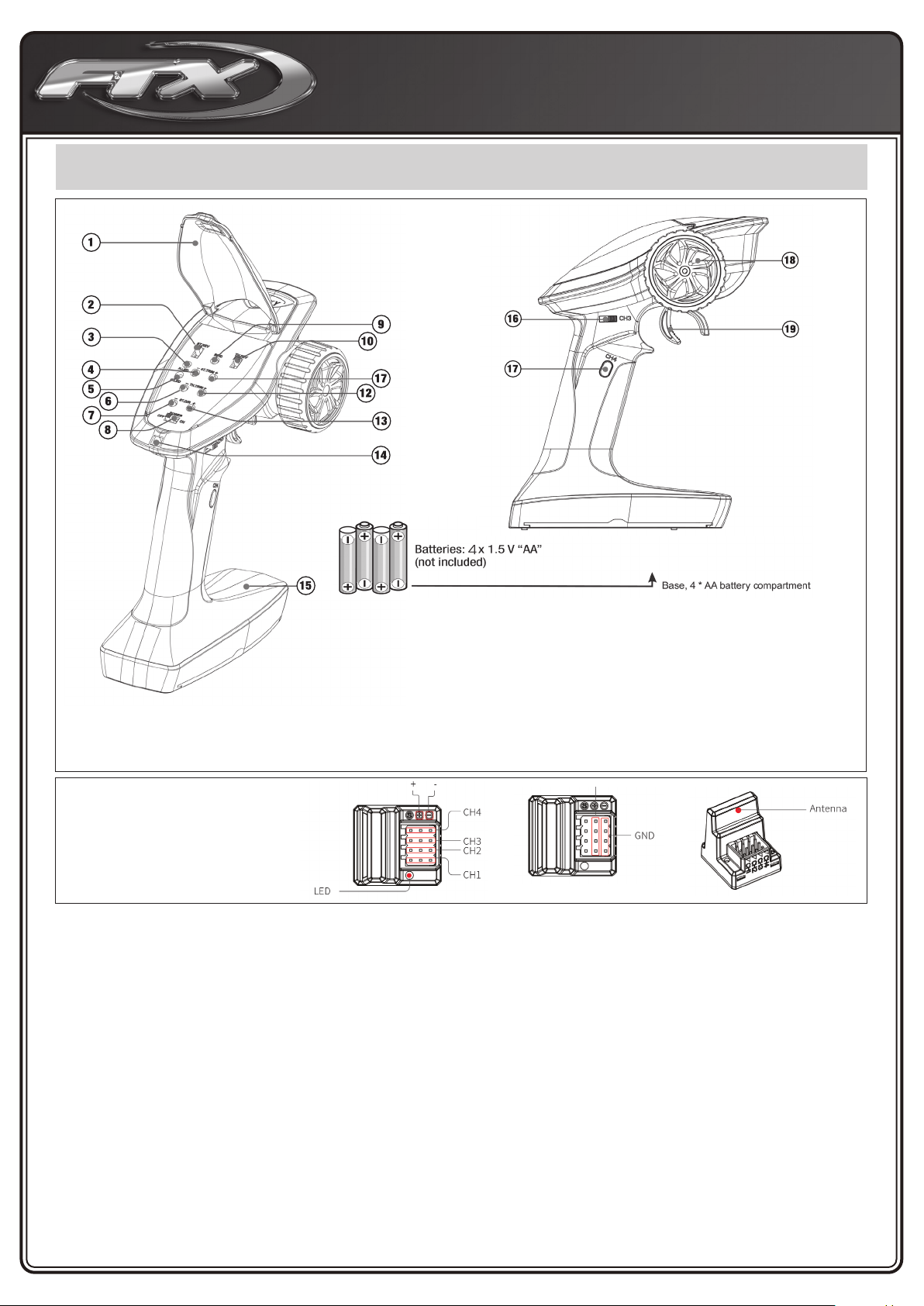
1. Connect the ESC, motor, receiver, battery and servo according to the following diagram:
“+” and “-” wires of the ESC are connected to the battery pack.
Attention: The incorrect polarity will damage the ESC immediately.
The control cable of the ESC (trio wires with black, red and white color) is connected to
the throttle channel of the receiver (Usually CH2). The “Motor +” and “Motor –” wires are
connected to ESC without any order.
If the motor runs in the opposite direction, please swap these two wire connections.
2. Set the Transmitter
Please set the “D/R”, “EPA” and “ATL” to 100% for throttle channel (for transmitter without
LCD, please turn the knobs to the maximum value), and set the “TRIM” of the throttle channel
to 0 (for transmitter without LCD, please turn the TRIM knob to its neutral position).
For FutabaTM and the similar transmitters, the direction of throttle
channel shall be set to “REV”, while other radio systems shall be set to “NOR”.
The “Fail Save” function of the radio system is strongly recommended to be activated. Please
make sure that the motor can be stopped when the “Fail Save” happens.
3. Throttle Range Setting (Throttle Range Calibration)
In order to make the ESC match the throttle range of different transmitters, the calibration of
the ESC is necessary.
To calibrate the ESC, please turn on the transmitter, keep throttle stick at its neutral position,
wait for 3 seconds to let the ESC execute self-test and automatic throttle calibration. When the
ESC is ready to run, a long beep sound is emitted from the motor.
Note: Please calibrate the throttle range again when using a new transmitter or changing the
settings of the neutral position of throttle channel, D/R, ATV, ATL or EPA parameters,otherwise
the ESC may not work properly.
BEEP SOUND AND LED STATUS
SET THE ESC
The ESC is programmed by the jumpers
(Tweezers are recommended to plug and unplug the jumper).
PROTECTION FUNCTIONS
1. Low voltage Cut-off (LVC) protection: If the voltage of battery pack is lower than the
threshold for 2 seconds, the ESC will enter the protection mode.
When the car stops, the red LED blinks to indicate the low voltage cut-off protection has been
activated.
Table A: LVC protection for WP-1060-BRUSHED, WP-1040-
BRUSHED, WP-860-DUAL BRUSHED (F/B/R or F/B mode).
Model WP-1040-BRUSHED
WP-1040-BRUSHED-Crawler & Boat *
Cont. / Burst Current Forward: 40A / 180A
Backward: 20A / 90A
Input 2-3S Lipo, 5-9 Cells NiMH
Cars Applicable 1:10 on-road, off-road Buggy, Truggy, SCT
1:10 Crawler, Tank & Boat
Motor
Limit
2S Lipo or
5-6 cells NiMH
3S Lipo or
7-9 cells NiMH
540 or 550 size motor ≥12T
or RPM < 30000 @7.2V
540 or 550 size motor ≥18T
or RPM < 20000 @7.2V
Resistance Fwd: 0.002 Ohm, Bwd: 0.004 Ohm
Built-in BEC 2A/6V (Linear mode BEC)
Dimension &
Weight WP-1040-BRUSHED: 46.5*34*28.5, 65g
WP-1040-BRUSHED-CRAWLER: 46.5*34*28.5, 70g
Neutral Point Top point of forward
direction Top point of backward
direction
THROTTLE STICK POSITION
User Manual of Water-Proof Brushed Speed Controller (RTR Version) HW-SM690ENG-V3-20160603Page - 1 -
Thanks for purchasing our electronic speed controller(ESC). The power system for RC model can be very
dangerous, please read this manual carefully. In that we have no control over the correct use, installation,
application, or maintenance of our products, no liability shall be assumed nor accepted for any damages,
losses or costs resulting from the use of the product.
【【FEATURES】】
1. Water-proof and dust-prooffor all weather races.
2. Small size with built-in capacitor module.
3. Automatic throttle range calibration, easy to use.
4. Multiple protections: Low voltage cut-off protection for Lipo or NiMH battery / Over-heat protection / Throttle signal
loss protection.
5. Easily programmed with the jumpers.
【【SPECIFICATIONS】】
* There are 2 kinds of WP-1040-BRUSHED-Crawler& Boat speed controllers, one has 1 output for 1 motor, and the other
one has 2 outputs for 2 motors (2 motors work synchronously).
** The WP-860-DUAL BRUSHED has 2 outputs to drive 2 motors synchronously. When driving 2 motors, the Turns of the
motors need to be increased.
【【BEGIN TO USE】】
1. Connect the ESC, motor, receiver, battery and servo according to the following diagram
“+” and “-” wires of the ESC are connected to the battery pack.
Attention: The incorrect polarity will damage the ESC immediately.
The control cable of the ESC (trio
wires with black, red and white color)
is connected to the throttle channel
of the receiver (Usually CH2). The
“Motor +” and “Motor –” wires are
connected to ESC without any order.
If the motor runs in the opposite
direction, please swap these two
wire connections.
2. Set the Transmitter
Please set the “D/R”, “EPA” and
“ATL” to 100% for throttle channel
(for transmitter without LCD, please
turn the knobs to the maximum
value), and set the “TRIM” of the
throttle channel to 0 (for transmitter
without LCD, please turn the TRIM
knob to its neutral position).
For FutabaTM and the similar
transmitters, the direction of throttle
channel shall be set to “REV”, while
other radio systems shall be set to “NOR”.
The “Fail Save” function of the radio system is strongly recommended to be activated. Please make sure that the motor
can be stopped when the “Fail Save” happens.
3. Throttle Range Setting (Throttle Range Calibration)
In order to make the ESC match the throttle range of different transmitters, the calibrationof the ESC is necessary.
To calibrate the ESC, please turn on the transmitter, keep throttle stick at its neutral position, wait for 3 seconds to let the
ESC execute self-test and automatic throttle calibration. When the ESC is ready to run, a long beep sound is emitted
from the motor.
Note: Please calibrate the throttle range again when using a new transmitter or changing the settings of the neutral
position of throttle channel, D/R, ATV, ATL or EPA parameters,otherwise the ESC may not work properly.
【【BEEP SOUND AND LED STATUS】】
The Meaning of Beep Sound
LED Status
1 short Beep: The battery is NiMH/NiCd
2 short Beeps: The battery is 2S Lipo
3 short Beeps: The battery is 3S Lipo
4 short Beeps: The battery is 4S Lipo
1 long Beep: Self-test and throttle calibration is
OK, the ESC is ready to run
When the throttle stick is in neutral range, red LED is off
Forward, brake or reverse at partial throttle, red LED blinks
Forward, brake or reverse at full throttle, red LED is solid
【【THROTTLE STICK POSITION】】
【【SET THE ESC】】
The ESC is programmed by the jumpers
(Tweezers is recommended to plug and unplug the jumper).
Model
WP-1040-BRUSHED
WP-1040-BRUSHED-Crawler& Boat *
WP-1060-BRUSHED
Cont. / Burst Current
Forward: 40A / 180A
Backward: 20A / 90A
Forward: 60A / 360A
Backward: 30A / 180A
Input
2-3S Lipo, 5-9 Cells NiMH
Cars Applicable
1:10 on-road, off-road Buggy, Truggy, SCT
1:10 Crawler, Tank &Boat
Motor
Limit
2S Lipoor
5-6 cells NiMH
540 or 550 size motor ≥12T
or RPM < 30000 @7.2V
540 or 550 size motor ≥ 8T
or RPM <45000 @7.2V
3S Lipo or
7-9 cells NiMH
540 or 550 size motor ≥18T
or RPM < 20000 @7.2V
540 or 550 size motor ≥13T
or RPM <30000 @7.2V
Resistance
Fwd: 0.002 Ohm, Bwd: 0.004 Ohm
Fwd: 0.0008 Ohm, Bwd: 0.0016 Ohm
Built-in BEC
2A/6V (Linear mode BEC)
3A/6V (Switch mode BEC)
Dimension&
Weight
WP-1040-BRUSHED: 46.5*34*28.5, 65g
WP-1040-BRUSHED-CRAWLER: 46.5*34*28.5, 70g
36*30*18, 40g
Model
WP-1625-BRUSHED
WP-1625-BRUSHED-Crawler
WP-860-DUAL BRUSHED
Cont. / Burst Current
Forward: 25A / 100A
Backward: 25A / 100A
Forward: 60A / 360A
Backward: 30A / 180A
Input
2-3S Lipo, 5-9 Cells NiMH
2-4S Lipo, 10-12 Cells NiMH
Cars Applicable
1:18 & 1:16 on-road, off-road
1:18 & 1:16 Crawler and Boat
1:8 on-road, off-road, Buggy, Truggy, Monster
Crawler and Boat
Motor
Limit
2S Lipoor
5-6 cells NiMH
280, 370 or 380 size motor
or RPM < 30000 @7.2V
540, 550 or 775 size motor ≥12T
or RPM < 30000 @7.2V
3S Lipo or
7-9 cells NiMH
280, 370 or 380 size motor
or RPM <20000 @7.2V
540, 550 or 775 size motor ≥18T
or RPM <20000 @7.2V
4S Lipoor
10-12cells NiMH
Not Available
540, 550 or 775 size motor ≥24T
or RPM <15000 @7.2V
Resistance
Fwd: 0.003 Ohm, Bwd: 0.003 Ohm
Fwd: 0.001 Ohm, Bwd: 0.002 Ohm
Built-in BEC
1A/6V(Linear mode BEC)
3A/5V(Switch mode BEC)
Dimension&
Weight
34mm*24mm*14mm, 23.5g
46mm*36mm*26.3mm, 73g
SPEED CONTROL CONNECTION DIAGRAM
The Meaning of Beep Sound
• 1 short Beep: The battery is NiMH/NiCd
• 2 short Beeps: The battery is 2S Lipo
• 3 short Beeps: The battery is 3S Lipo
• 4 short Beeps: The battery is 4S Lipo
• 1 long Beep: Self-test and throttle calibration is OK, the ESC is ready to run
LED Status
• When the throttle stick is in neutral range, red LED is off
• Forward, brake or reverse at partial throttle, red LED blinks
• Forward, brake or reverse at full throttle, red LED is solid
User Manual of Water-Proof Brushed Speed Controller (RTR Version) HW-SM690ENG-V3-20160603Page - 2 -
【PROTECTION FUNCTIONS】
1. Low voltage Cut-off (LVC) protection: If the voltage of battery pack is lower than the threshold for 2 seconds, the
ESC will enter the protection mode.
When the car stops, the red LED blinks to indicate the low voltage cut-off protection has been activated.
Table A: LVC protection for WP-1060-BRUSHED, WP-1040-BRUSHED, WP-860-DUAL BRUSHED (F/B/R or F/B
mode).
2S Lipo
3S Lipo
4S Lipo
5-9 cells NiMH
Output reduces 50% at 6.5V
Output cuts off at 6.0V,
cannot be recovered
Output reduces 50% at 9.75V
Output cuts off at 9.0V, cannot
be recovered
Output reduces 50% at 13V
Output cuts off at 12V, cannot
be recovered
Output reduces 50% at 4.5V
Output cuts off at 4.0V, cannot
be recovered
Table B: LVC protection for WP-1625-BRUSHED-Crawler, WP-1040-BRUSHED-Crawler&Boat, WP-860-DUAL
BRUSHED (Crawler or Boat mode).
2S Lipo
3S Lipo
4S Lipo
5-9 cells NiMH
Output cuts off at 6.5V.
If the throttle stick moves to
neutral and then up again, the
output can be recovered to
50%.
If the voltage drops to 6.5V
again, the above process
repeats in circles.
Output cuts off at 9.75V.
If the throttle stick moves to
neutral and then up again, the
output can be recovered to
50%.
If the voltage drops to 9.75V
again, the above process
repeats in circles.
Output cuts off at 13V.
If the throttle stick moves to
neutral and then up again, the
output can be recovered to
50%.
If the voltage drops to 13V
again, the above process
repeats in circles
Output cuts off at 4.5V.
If the throttle stick moves to
neutral and then up again, the
output can be recovered to
50%.
If the voltage drops to 4.5V
again, the above process
repeats in circles.
2. Over-heat protection: When the internal temperature of the ESC is higher than 100 Celsius degree or 212
Fahrenheit degree for 5 seconds, the ESC will reduce and cut off the output power.
When the car stops, the red LED blinks to indicate the over-heat protection has been activated. If the ESC cools
down to 80 Celsius degree (176 Fahrenheit degree) the output power is recovered to normal state.
3. Throttle signal loss protection: The ESC will cut off the output power if the throttle signal has been lost for 0.1 second.
The “Fail Save” function of the radio system is strongly recommended to be activated.
【THE DIFFERENCE BETWEEN “BRUSHED” AND “BRUSHED-CRAWLER& BOAT” ESC】
1. “Brushed” and “Brushed-Crawler& Boat” ESCs have different backward-running modes.
“Brushed” ESC uses “Double-Click” method to make the car go backward. When you move the throttle stick from
forward zone to backward zone for the first time, the ESC begins to brake the motor, the motor speeds down but
still running, so the backward action is NOT happened at this moment. When the throttle stick is moved to the
backward zone again (The 2nd “click”), if the motor speed is slowed down to zero (i.e. stopped), the backward
action will be activated. The “Double-Click” method prevents mistakenly reverse when the brake function is
frequently used in steering.
“Brushed-Crawler& Boat” ESC uses “Single-click” to make the car go backward. When you move the throttle stick
from forward zone to backward zone, the car will go backward immediately. This mode is common for the Rock
Crawler and tank.
2. The maximum reverse force (for backward running) is 50% for the general “Brushed” ESC, 100% for the “Crawler”
mode of a “Brushed-Crawler & Boat” ESC, and 25% for the "Boat" mode of a “Brushed-Crawler & Boat” ESC.
3. The Low Voltage Cut-off Protection modes are different (Please check the instructions in the section of
“PROTECTION FUNCTIONS”).
【TROUBLE SHOOTING】
Trouble
Possible Reason
Solution
After power on, motor can’t work, no
sound is emitted, and LED is off.
The ESC doesn’t get its working
voltage; Connections between
battery pack and ESC are
broken.
Check the battery wires connection
or replace the defective connectors.
Switch is damaged.
Replace the switch.
After power on, motor can’t work; red
LED blinks.
Throttle signal is abnormal.
Check the throttle wire connection;
make sure it is plugged into the
throttle channel of the receiver.
Automatic throttle range
calibration is failed.
Set the “TRIM” of throttle channel to
0 or turn the knob to its neutral
position.
The car runs backward while giving
throttle.
(The motor runs in the opposite
direction)
The wire connections between
ESC and the motor need to be
changed.
Swap two wire connections between
the ESC and the motor.
The car can’t go backward.
The jumper position is wrong.
Check the jumper and plug it to the
correct position.
The neutral point of throttle
channel is changed or drifted.
Set the “TRIM” of throttle channel to
0 or turn the knob to its neutral
position.
The car can’t go forward, but can go
backward.
The direction of throttle channel
is not correct.
Reset the direction of throttle
channel from original “NOR” to
“REV”, or from original “REV” to
“NOR”.
The motor doesn’t work, but the LED in
the ESC works normally.
The connections between motor
and ESC are broken.
Check the connections and replace
the defective connectors.
Motor is damaged.
Replace the motor.
The motor suddenly stops running
while in working state
The throttle signal is lost.
Check the transmitter and the
receiver.
Check the throttle wire connection.
Low voltage cut-offprotection
or Over-heat cut-off protection
has been activated.
Replace the battery pack, or cool
down the ESC.
The car cannot get top speed and the
red LED doesn’t solid on at full throttle
Some setting in the transmitter
are incorrect.
Check the settings.
Set D/R, EPA, ATL to 100% or turn
the knobs to maximum value.
Set TRIM to 0 or turn the knob to its
neutral position.
Motor is cogging when accelerated
quickly.
The battery has limited
discharge ability.
Use battery with better discharge
ability.
Motor RPM is too high, the gear
ratio is too aggressive.
Use motor with lower RPM, or use
smaller pinion to get softer gear
ratio.
Something wrong in the driving
system of the car.
Check the driving system of the car.
Output reduces 50%
at 6.5V Output cuts
off at 6.0V, cannot be
recovered
Output reduces 50%
at 9.75V Output cuts
off at 9.0V, cannot be
recovered
Output reduces 50%
at 13V Output cuts
off at 12V, cannot be
recovered
Output reduces 50%
at 4.5V Output cuts
off at 4.0V, cannot be
recovered
2S Lipo 3S Lipo 4S Lipo 5-9 cells NiMH

8
CHARGING/INSTALLING THE BATTERY.
• Always store your model with the battery pack unplugged and removed.
• Always charge your battery away from the vehicle.
The included USB charger will take approximately 4 hours to charge a discharged
2000mAh battery.
• When charging the Red LED will be solid.
• When the battery is fully charged the Green LED will be solid.
• The battery will become warm to touch when charged, but not hot.
• If the battery is hot, stop charging immediately. Disconnect the battery from the charger
as soon as the charger LED turns green.
NOTES ON BATTERY USE:
• Always allow the battery cool after use, before recharging.
• Always inspect the battery before charging.
• Any bare wires, split heat shrink or leakage is a sure sign of abuse.
• Never attempt to charge dead or damaged batteries.
• Do not disassemble the battery or cut the connector wires.
• If the battery connector gets hot enough to melt there is most likely a serious problem
with your model, driveline, battery wires or speed controller. Find and correct the
problem before installing another charged battery pack.
• NEVER charge the battery unattended incase of overcharging, you need to be able to
monitor the battery during charging.
• Charge away from ammable objects and on a non-ammable surface incase the
battery becomes too hot.
TABLE B: LVC PROTECTION FOR WP-1625-BRUSHED-CRAWLER, WP-1040-BRUSHED-
CRAWLER&BOAT, WP-860-DUAL BRUSHED (CRAWLER OR BOAT MODE).
2. Over-heat protection: When the internal temperature of the ESC is higher than 100 ˚C or 212
Fahrenheit degree for 5 seconds, the ESC will reduce and cut off the output power.
When the car stops, the red LED blinks to indicate the over-heat protection has been
activated. If the ESC cools down to 80 Celsius degree (176 Fahrenheit degree) the output
power is recovered to normal state.
3. Throttle signal loss protection: The ESC will cut off the output power if the throttle signal
has been lost for 0.1 second. The “Fail Save” function of the radio system is strongly
recommended to be activated.
THE DIFFERENCE BETWEEN “BRUSHED” AND “BRUSHED-CRAWLER & BOAT” ESC
1. “Brushed” and “Brushed-Crawler& Boat” ESCs have different backward-running modes.
“Brushed” ESC uses “Double-Click” method to make the car go backward. When you move
the throttle stick from forward zone to backward zone for the rst time, the ESC begins to
brake the motor, the motor speeds down but still running, so the backward action is NOT
happened at this moment. When the throttle stick is moved to the backward zone again
(The 2nd “click”), if the motor speed is slowed down to zero (i.e. stopped), the backward
action will be activated. The “Double-Click” method prevents mistakenly reverse when the
brake function is frequently used in steering.
“Brushed-Crawler& Boat” ESC uses “Single-click” to make the car go backward. When
you move the throttle stick from forward zone to backward zone, the car will go backward
immediately. This mode is common for the Rock Crawler and tank.
2. The maximum reverse force (for backward running) is 50% for the general “Brushed” ESC,
100% for the “Crawler” mode of a “Brushed-Crawler & Boat” ESC, and 25% for the “Boat”
mode of a “Brushed-Crawler & Boat” ESC.
3. The Low Voltage Cut-off Protection modes are different (Please check the instructions in
the section of “PROTECTION FUNCTIONS”).
TROUBLE SHOOTING
• After power on, motor can’t work, no sound is emitted,
and LED is off.
• After power on, motor can’t work; red LED blinks.
• The car runs backward while giving throttle.
(The motor runs in the opposite direction).
• The car can’t go backward.
• The car can’t go forward, but can go backward.
• The motor doesn’t work, but the LED in the ESC works
normally.
• The motor suddenly stops running while in working state.
• The car cannot get top speed and the red LED doesn’t
solid on at full throttle.
• Motor is cogging when accelerated quickly.
• The ESC doesn’t get its working voltage; Connections
between battery pack and ESC are broken.
• Switch is damaged.
• Throttle signal is abnormal.
• Automatic throttle range calibration is failed.
• The wire connections between ESC and the motor need to
be changed.
• The jumper position is wrong.
• The neutral point of throttle channel is changed or drifted.
• The direction of throttle channel is not correct.
• The connections between motor and ESC are broken.
• Motor is damaged.
• The throttle signal is lost.
• Low voltage cut-offprotection or Over-heat cut-off
protection has been activated.
• Some setting in the transmitter are incorrect.
• The battery has limited discharge ability.
• Motor RPM is too high, the gear ratio is too aggressive.
• Something wrong in the driving system of the
car.
• Check the battery wires connection or replace the
defective connectors.
• Replace the switch.
• Check the throttle wire connection; make sure it is
plugged into the throttle channel of the receiver.
• Set the “TRIM” of throttle channel to 0 or turn the knob to
its neutral position.
• Swap two wire connections between the ESC and
the motor.
• Check the jumper and plug it to the correct position.
• Set the “TRIM” of throttle channel to 0 or turn the knob to
its neutral position.
• Reset the direction of throttle channel from original “NOR”
to “REV”, or from original “REV” to “NOR”.
• Check the connections and replace the defective
connectors.
• Replace the motor.
• Check the transmitter and the receiver.
• Check the throttle wire connection.
• Replace the battery pack, or cool down the ESC.
• Check the settings. Set D/R, EPA, ATL to 100% or turn the
knobs to maximum value. Set TRIM to 0 or turn the knob
to its neutral position.
• Use battery with better discharge ability.
• Use motor with lower RPM, or use smaller pinion to get
softer gear ratio.
• Check the driving system of the car.
Problem Reaction Solution
Output cuts off at
6.5V.
If the throttle stick
moves to neutral
and then up again,
the output can be
recovered to 50%.
If the voltage drops
to 6.5V again, the
above process
repeats in circles.
Output cuts off at
9.75V.
If the throttle stick
moves to neutral
and then up again,
the output can be
recovered to 50%.
If the voltage drops
to 9.75V again,
the above process
repeats in circles.
Output cuts off
at 13V.
If the throttle stick
moves to neutral
and then up again,
the output can be
recovered to 50%.
If the voltage drops
to 13V again, the
above process
repeats in circles
Output cuts off at
4.5V.
If the throttle stick
moves to neutral
and then up again,
the output can be
recovered to 50%.
If the voltage drops
to 4.5V again, the
above process
repeats in circles.
2S Lipo 3S Lipo 4S Lipo 5-9 cells NiMH
CHARGING

9
Getting Started
Switch on transmitter. Hold vehicle clear of the ground, connect battery pack and
switch on receiver. Bind the Transmitter and receiver if required.
Test the transmitter to check control of the vehicle with wheels off the ground.
Start driving slowly and if the vehicle does not go straight, adjust steering trim dial
on Transmitter. For the very rst run use the throttle gently, to gradually bed in the
motor brushes and help the driver become accustomed to the vehicles behaviour
and controls.
PLEASE NOTE:
Although the electronics are waterproof the rest of car can be subjected to damage
if running in excessively wet or submerged conditions.
After Run.
Switch off the receiver power, switch off the transmitter and lower the aerial.
Disconnect the battery and remove it from the vehicle, allow it to cool before
recharging. If you have a second charged battery all ready to use, still allow the
vehicle to cool slightly before continuing.
Regular maintenance.
Frequently check the whole vehicle for loose or missing xings. Use thread lock on
any replacement screws into metal threads.
Frequently check rotating parts are free from grass, string etc. that might bind
their motion and over stress the motor or speed controller. Remove the wheels
occasionally and check behind the mounting hex for obstructions or anything that
might have been wrapped around the axle and caused extra drag.
Shock absorbers will wear prematurely if used in dirty dusty conditions. Replace oil
and seals as required to keep a smooth dampening action.
Warranty
Due to the nature of this product and potential use FTX warrants it to be free
of material and workmanship defects when new. FTX will at its sole discretion
repair or replace defective components free of charge within 30 days from date of
purchase. This warranty does not cover wear and tear, crash or impact damage,
modications, component water damage failure to perform maintenance or damage
from improper use. Proof of purchase date will be required to action any warranty
claims. In no case shall FTX’s liability exceed the original cost of the purchased kit.
SHORT RUNTIME:
Battery damaged/not
charged
Motor dirty or brushes worn
Drivetrain binding
SLUGGISH ACTION:
Motor dirty or brushes worn
Bind in drive train
Battery running low on
power
MOTOR/ESC OVERHEAT:
Over-geared
Binding transmission.
Seized axle bearing.
Motor binding
MOTOR SPINS BUT VEHICLE
REFUSES TO MOVE:
Gears damaged.
Gears loose on shaft.
Drive shaft broken or
missing.
POOR RANGE OR FAILS TO
OPERATE:
Transmitter batteries low
Vehicle Battery Low.
Transmitter switched off
Transmitter/receiver aerial
not extended.
ESC switched off or battery
not connected.
Loose connectors/wires.
Instructions for disposal.
Environmental Protection Notes & WEEE
The crossed-out wheeled bin symbol shown here, which may be found on the
product itself, in the operating instructions or on the packaging, is in accordance
with the Waste Electrical and Electronic Equipment (WEEE) Directive. Individual
markings indicate which materials can be recycled and re-used. You can make an
important contribution to the protection of our common environment by re-using
the product, recycling the basic materials or recycling redundant equipment in
other ways.
When this product comes to the end of its useful life, you must not dispose of it
in the ordinary domestic waste. Many electrical items that we throw away can
be repaired or recycled. Recycling items helps to save natural resources and
also reduces the environmental and health impacts that are linked with sending
electrical goods to landll. The correct method of disposal is to take it to your local
collection point for recycling electrical and electronic equipment. You can go to
recycle-more.co.uk for details of locations.
Alternatively FTX can offer our customers free take-back of their WEEE on a like-
for-like basis when they buy a new Electrical or Electronic product from us.
For example, if a customer bought a new radio system from us or a dealer, we
would accept their old radio and prevent it going into a landll site by disposing
of it safely. Customers must return their old WEEE item to us within 28 days of
purchasing their new item.
Remove batteries from your device and dispose of them at your local collection
point for batteries. If you don’t know the location of your nearest disposal centre,
please enquire at your local council ofce.
Trouble shooting guide.
CML Distribution, Saxon House, Saxon Business Park, Hanbury Road,
Bromsgrove, B60 4AD. WEE/GB4215VX
CML

10
Le FTX Gladius 4x4, une voiture de trail à l’échelle 1/10 prête à rouler
Merci d’avoir choisi le FTX Gladius 4x4 électrique.
Ce modèle est monté d’usine, l’électronique est pré installée et
réglée pour permettre un démarrage et du plaisir le
plus rapidement possible.
This 1/10th scale model has been factory
assembled and all electrics installed and
set up to make it the easiest possible
introduction to the sport of driving RC cars.
Attention: lisez l’intégralité du manuel
pour exploiter au mieux la voiture et
éviter des dommages mécaniques
ou corporels. Ce modèle n’est pas
un jouet, il doit être manipulé avec
précaution. Utilisé dans de mauvaises
conditions, ce modèle peut causer des
dommages.
Ce modèle n’est pas fait pour
être utilisé par un enfant sans la
surveillance directe d’un adulte.
Il est essentiel de lire et de suivre les instructions et
les recommandations de ce manuel pour entretenir
et faire évoluer votre modèle dans de bonnes conditions.
Mesures de sécurité:
• Vous êtes responsable lors de l’évolution de ce modèle, veillez à ne pas vous mettre en danger, à mettre en danger le modèle ou la propriété d’autrui.
• Ce modèle radiocommandé peut être perturbé par d’autres sources d’onde radio, ce qui peut entrainer la perte momentanée du contrôle de la voiture.
• Age recommandé : 14 ans, ceci n’est pas un jouet, ce produit n’est pas fait pour être utilisé par un enfant sans surveillance.
Suivez consciencieusement les instructions suivantes :
• Ne jamais évoluer avec des batteries d’émission faibles
• Toujours évoluer dans une zone dégagée, loin de la circulation et de la foule
• Ne jamais évoluer dans une rue ou un endroit fréquenté
• Toujours garder le modèle dans son champ de vision
• Gardez hors de portée des enfants tous les composants de
petite taille, électriques ou chimiques
• Tenez le modèle hors de portée de l’eau (la rouille peut
causer des dommages irréversibles au modèle)
• Faites attention aux pièces en rotations, axes, pignons
etc.
• Les débutants doivent prendre conseil auprès de
personnes plus expérimentées
• Faites attention lors de l’utilisation des outils
• Attention à ne pas mettre les doigts ou d’autres parties
du corps en contact avec les pièces en rotation
• Faites attention lors du transport, de la maintenance ou de
la réparation, certaines pièces peuvent être coupantes.
• NE JAMAIS toucher les composants tels que le moteur, le variateur ou les
batteries après utilisation, ces pièces peuvent être chaudes
• Lorsque vous changez de fréquence d’émission assurez-vous que les quartz de
fréquence sont bien positionnés (RX pour récepteur et TX pour l’émetteur)
• Toujours éteindre en premier la voiture avant l’émetteur
• Vériez le bon fonctionnement de la voiture les roues dans le vide (en prenant les précautions nécessaires)
• Prolongez la durée de vie du moteur en le préservant de la surchauffe (la durée de vie du moteur dépend aussi de la fréquence de roulage, des changements rapide de
direction avant/arrière, des conditions de roulage difciles poussière/boue des utilisations abusives tirer/pousser des objets)
Contents:
1 FTX Gladius 1/10ème prêt à rouler électrique
1 Emetteur à volant fréquence 2.4GHz
1 Chargeur: USB 500mA
1 Batterie: 7.2V 2000mAh NiMH
FRANÇAIS

11
FRANÇAIS
EQUIPMENTS REQUIS POUR LA MAINTENANCE:

12
FRANÇAIS
DÉCOUVERTE DE VOTRE TÉLÉCOMMANDE
Installation des piles
1. Ouvrez le couvercle du compartiment des piles
2. Insérez 4 piles AA entièrement chargées dans le compartiment
tout en vériant bien les polarités et leur bon montage.
3. Remettez en place le couvercle
NOTE :
La télécommande possède une alarme en cas de faible tension : Lorsque
les piles sont en dessous de 4.2V, la G.LEC sur tableau de bord va clignoter
lentement.
Liaison du récepteur et de la télécommande (BIND)
An d’assurer le meilleur signal possible, positionnez le récepteur de manière
à ce que l’antenne soit positionnée vers le haut.
La télécommande et le récepteur ont déjà été reliés en usine.
1. Allumez la télécommande tout en maintenant le bouton BIND
pour entrer dans le mode bind. La G.LED va clignoter
rapidement. Une fois dans le mode bind, vous pouvez relâcher le
bouton de bind.
2. Le récepteur va automatiquement rentrer en mode bind lorsque
vous allez l’allumer.
3. Lorsque la liaison est eectuée, la LED du récepteur va clignoter
lentement et la LED de la télécommande va rester allumer une fois
redémarrée.
NOTE:
Lors de la liaison, mettez d’abord la télécommande en mode bind puis le
récepteur.
Calibration des commandes
Cette fonction permet de déterminer la position neutre de la gâchette des gaz
et du volant de direction.
Chaque télécommande est calibrée avant de partir de l’usine, cependant si
vous avez besoin de la recalibrer, voici les étapes à suivre :
1. Tournez au max le volant dans le sens des aiguilles d’une montre, pous-
sez au max la gâchette des gaz vers l’avant et allumer la télécommande
pour entrer dans le mode de calibration. Les LED R.LED et G.LED vont
asher 2 fois.
2. Calibration de la direction : Tournez au max le volant dans le sens des
aiguilles d’une montre puis à fond dans le sens inverse aux aiguilles d’une
montre.
Lorsque cette calibration est terminée, la R.LED va s’éteindre.
3. Calibration des gaz : Tirez au max la gâchette des gaz vers l’arrière puis à
fond vers l’avant.
Lorsque cette calibration est terminée, la G.LED va s’éteindre.
4. Une fois la calibration eectuée, appuyer sur le bouton de bind pour
sauvegarder et quitter.
17
1. Capot de protection
2. Interrupteur d’inversion de la direction (ST.REV)
3. LED d’indication de l’alimentation (R.LED)
4. Trim de la direction (ST.TRIM-)
5. LED verte d’indication du statuts (G.LED)
6. Trim des gaz (TH.TRIM-)
7. D/R de la direction (ST.D/R-)
8. Interrupteur d’alimentation
9. Bouton de BIND (BIND)
10. Inversion des gaz (TH.REV)
11. Trim de la direction (ST.TRIM+)
An d’assurer le meilleur signal possible,
positionnez le récepteur de manière à
ce que l’antenne soit positionnée vers
le haut.
12. Trim des gaz (TH.TRIM+)
13. D/R de la direction (ST.D/R)
14. Point de xation
15. Socle, compartiment des 4 piles AA
16. Interrupteur 3 positions (CH3)
17. Bouton (CH4)
18. Roue de direction, son degré de rotation maximale est
de 35° du centre vers la gauche ou vers la droite (CH1)
19. Gâchette de direction, son degré de rotation est de 12
du centre vers l’avant ou vers l’arrière (CH2)
Vue générale du récepteur
Antenne

13
FRANÇAIS
GESTION DE VOTRE VOITURE
1. METTRE LA RADIO SUR ON 2. METTRE SUR ON INTERRUPTEUR
3. ASSURE UNE BONNEPERFORMANCE DE PILOTAGE
Mettre le bouton
d’allumage de
la radio sur ON.
Votre voiture est
automatiquement
appairer avec
votre radio.
L’ensemble
variateur/
recepteur se situe
sur ON comme
montré sur la
photo.
CENTRE TOURNE À GAUCHE
2. Tourner à droite pour permettre à
votre d’aller à gauche.
3. Tourner à gauche pour permettre à
votre voiture d’aller à droite.
4. VÉRIFIER LA REEPONSE DE LA GACHETTE
S’IL VOUS PLAÎT NOTEZ :
LE MODÈLE PASSE ENTRE LA MARCHE AVANT ET ARRIÈRE
INSTANTANÉMENT POUR UNE MANŒUVRABILITÉ À
FAIBLE VITESSE. UNE UTILISATION EXCESSIVE DE
CETTE FONCTIONNALITÉ PEUT ET VA ENDOMMAGER LA
TRANSMISSION ET L’ESC.
STOP!
A. B. C.
A. Tirer la gâchette en arrière pour accélérer? La lâcher pour décélérer et la
pousser pour freiner.
B. Pour arrêter la voiture, lâchette jusqu’au neutre.
C. Pousser la gâchette vers l’avant active la marche arrière.
TIRER CENTRE
POUSSER
EN
AVANT
TOURNE À DROITE
1. Pour que la voiture aille droite ne pas
tourner le volant (le laisser au centre).

14
FRANÇAIS
GESTION DE VOTRE VOITURE
5. RÉGLAGE DU TRIM DE DIRECTION
Accélérez tout doucement an de faire lentement
avancer la voiture. Appuyez-en même sur les
boutons droit et gauche pour régler l’orientation des
roues an que la voiture avance tout droit.
STEERING
6. RÉGLAGE DU TRIM D’ACCÉLÉRATION
7. RÉGLAGE DES BUTÉES DE DIRECTION
Le bouton de trim d’accélérateur est utilisé pour régler le
régime de ralenti de la voiture.
INDICATEUR LED:
• Lorsque vous utilisez les boutons de réglage du trim,
la LED clignote lentement pour un appui court et
rapidement pour un appui long.
• Quand la valeur du trim est au milieu, la LED clignote 2
fois lentement
• Quand la valeur du trim est au maximum vers la droite ou vers la gauche,
la LED ne clignote pas
THROTTLE TRIM
STEERING D/R
8. INVERSE DU SENS DE ROTATION DE LA DIRECTION ET DE L’ACCÉLÉRATEUR
Inversion de la direction:
Pour changer le sens de rotation de la direction, montez le bouton « ST R/N » pendant quelques
secondes jusqu’à entendre un « BIP » sonore, relâchez ensuite le bouton.
Inversion de l’accélérateur:
Cette fonction permet de changer le sens de rotation de l’accélération.
Si le bouton est en bas celle-ci est le sens normal tandis que si il est en haut, elle sera inversée.
INDICATEUR LED :
• Lorsque vous utilisez les boutons de réglage du trim, la LED clignote lentement
pour un appui court et rapidement pour un appui long.
• Quand la valeur du trim est au maximum la LED ne clignote pas.
Le bouton noté « ST/DR » est utilisé pour régler les ns
de course du servo de direction
Ajustable de 0 à 120% (100% par défaut), une pression
du bouton change la valeur de 5%
ST.D / R + : Augmente la course de direction
ST.D / R - : Réduit la course de direction

15
FRANÇAIS
Notice du Contrôleur de vitesse (ESC)
Merci d’avoir acheté notre contrôleur de vitesse (ESC). Les motorisations des voitures RC peuvent être
dangereuses, veuillez donc lire attentivement ce manuel. En aucun cas nous avons le contrôle sur l’utilisation
que vous en faites, son montage, son bon usage, ou sur la maintenance de nos produits. Donc nous assumons
et acceptons aucune responsabilité pour tous dégâts, pertes ou couts qui pourraient résulter de l’utilisation
de ce produit.
Fonctionnalités:
• Water-proof et résistant à la poussière an de rouler dans toutes les conditions
• Taille réduite avec le module condensateur intégré
• Calibration de la plage des gaz automatique, et simple à utiliser
• Protections multiples : Protection (Cut off) contre les tensions faibles pour les batteries LiPo et NiMh /
Protection de surchauffe / Protection (FailSafe) en cas de perte du signal des gaz
• Facilement programmable avec les prises
Spécications:
* Il y a 2 types de contrôleur de vitesse WP – 1040 – Brushed - Crawler & Bateau, l’un possède 1 sortie pour 1
moteur, l’autre possède 2 sorties pour 2 moteurs (les moteurs fonctionnent de manières synchronisée)
** Le WP – 860 – Dual à charbon possède 2 sorties pour contrôler 2 moteurs de façon synchronisée. Lorsque
vous utilisez les 2 moteurs, le nombre de Tours (T) des moteurs doit être augmenté.
Commencez à vous en servir
1. Branchez l’ESC, le moteur, le récepteur, la batterie et le servo en suivant le schéma et en
respectant bien les polarités + et – indiquées.
Attention : Une mauvaise polarité endommagerait immédiatement l’ESC.
Le câble de commande de l’ESC (celui composé de câbles noir, rouge et blanc) vient se
connecter sur la voie des gaz du récepteur (généralement la voie 2). Les polarités des
câbles du moteur (Moteur +) et (Moteur -) peuvent être branché dans les 2 sens. Si jamais
le moteur tourne dans le mauvais sens, il vous suft d’inverser le branchement de ces 2
câbles.
2. Régler la télécommande
Veuillez régler le Dual / Rate (D/R), le débattement (EPA) et les trims autour du neutre
(ATL) de la voie des gaz à 100% et réglez le Trim des gaz de la voie des gaz à 0 (si votre
télécommande ne possède pas d’écran de réglage, utilisez les potentiomètres).
Pour les télécommandes Futaba ou similaire, vous devez régler le sens de la commande
des gaz sur inversé (REV). Pour les autres télécommandes réglez le sens de la commande
des gaz dans le sens classique (NOR).
1. Réglage du débattement de la voie des gaz (calibration)
An que votre ESC détermine la plage de la commande des gaz de votre télécommande,
vous devez effectuer une calibration.
An de calibrer votre ESC, allumez votre télécommande, laissez la gâchette des gaz au
neutre et attendez 3 sec pendant que l’ESC réalise des tests et effectue une calibration
automatique. Une fois l’ESC prêt, un long beep est émis par le moteur.
Note : Effectuez la calibration de la voie des gaz à chaque fois que vous utilisez une
nouvelle télécommande ou que vous changez le réglage de la position du neutre de la voie
des gaz ou le D/R, ATV, ATL ou EPA, dans le cas contraire, l’ESC pourrait ne pas fonctionner
correctement.
Signications des beeps et de la LED
Régler l’ESC
L’ESC se programme grâce à une prise de servo spéciale
(Une pince à épiler est recommander pour brancher et débrancher la prise.
Fonctions de protection
1. Protection de faible tension (Cut off) : Si la tension de la batterie descend sous un certain
seuil pendant plus de 2 secondes, l’ESC entre en mode de protection. Lorsque la voiture
s’arrête, le LED rouge clignote indiquant que la protection de faible tension a été activé.
Table A : Protection faible tension pour les WP – 1060 – Brushed, WP – 1040
– Brushed et WP – 860 – Brushed (Marche avant / Frein / Marche arrière ou
Marche avant / Frein)
Modèle WP – 1040 – Brushed
WP – 1040 – Brushed - Crawler & Bateau*
Courant continu / pic Marche avant : 40 A / 180 A
Marche arrière : 20 A / 90 A
Entrée LiPo
Voitures adaptées 1/10 Piste, Tout-terrain Buggy, Truggy, SC
1/10 Crawler, Tank & Bateau
Limitation
moteur
LiPo 2S ou NiMh
5-6 éléments
LiPo 3S ou NiMh
7-9 éléments
Moteur 540 ou 550 > 11T
ou RPM < 30000 @ 7.2 V
Moteur 540 ou 550 > 1èT
ou RPM < é0000 @ 7.2 V
Résistance Marche avant : 0.002 Ohm
Marche arrière : 0.004 Ohm
BEC intégré 2 A / 6 V (BEC avec mode linéaire)
Dimensions &
Poids WP – 1040 – Brushed : 46.5*34*28.5, 65g
WP – 1040 – Brushed - Crawler & Bateau* :
46.5*34*28.5, èàg
Neutre Butée en marche avant Butée en marche arrière
Position de la gâchette des gaz
User Manual of Water-Proof Brushed Speed Controller (RTR Version) HW-SM690ENG-V3-20160603Page - 1 -
Thanks for purchasing our electronic speed controller(ESC). The power system for RC model can be very
dangerous, please read this manual carefully. In that we have no control over the correct use, installation,
application, or maintenance of our products, no liability shall be assumed nor accepted for any damages,
losses or costs resulting from the use of the product.
【【FEATURES】】
1. Water-proof and dust-prooffor all weather races.
2. Small size with built-in capacitor module.
3. Automatic throttle range calibration, easy to use.
4. Multiple protections: Low voltage cut-off protection for Lipo or NiMH battery / Over-heat protection / Throttle signal
loss protection.
5. Easily programmed with the jumpers.
【【SPECIFICATIONS】】
* There are 2 kinds of WP-1040-BRUSHED-Crawler& Boat speed controllers, one has 1 output for 1 motor, and the other
one has 2 outputs for 2 motors (2 motors work synchronously).
** The WP-860-DUAL BRUSHED has 2 outputs to drive 2 motors synchronously. When driving 2 motors, the Turns of the
motors need to be increased.
【【BEGIN TO USE】】
1. Connect the ESC, motor, receiver, battery and servo according to the following diagram
“+” and “-” wires of the ESC are connected to the battery pack.
Attention: The incorrect polarity will damage the ESC immediately.
The control cable of the ESC (trio
wires with black, red and white color)
is connected to the throttle channel
of the receiver (Usually CH2). The
“Motor +” and “Motor –” wires are
connected to ESC without any order.
If the motor runs in the opposite
direction, please swap these two
wire connections.
2. Set the Transmitter
Please set the “D/R”, “EPA” and
“ATL” to 100% for throttle channel
(for transmitter without LCD, please
turn the knobs to the maximum
value), and set the “TRIM” of the
throttle channel to 0 (for transmitter
without LCD, please turn the TRIM
knob to its neutral position).
For FutabaTM and the similar
transmitters, the direction of throttle
channel shall be set to “REV”, while
other radio systems shall be set to “NOR”.
The “Fail Save” function of the radio system is strongly recommended to be activated. Please make sure that the motor
can be stopped when the “Fail Save” happens.
3. Throttle Range Setting (Throttle Range Calibration)
In order to make the ESC match the throttle range of different transmitters, the calibrationof the ESC is necessary.
To calibrate the ESC, please turn on the transmitter, keep throttle stick at its neutral position, wait for 3 seconds to let the
ESC execute self-test and automatic throttle calibration. When the ESC is ready to run, a long beep sound is emitted
from the motor.
Note: Please calibrate the throttle range again when using a new transmitter or changing the settings of the neutral
position of throttle channel, D/R, ATV, ATL or EPA parameters,otherwise the ESC may not work properly.
【【BEEP SOUND AND LED STATUS】】
The Meaning of Beep Sound
LED Status
1 short Beep: The battery is NiMH/NiCd
2 short Beeps: The battery is 2S Lipo
3 short Beeps: The battery is 3S Lipo
4 short Beeps: The battery is 4S Lipo
1 long Beep: Self-test and throttle calibration is
OK, the ESC is ready to run
When the throttle stick is in neutral range, red LED is off
Forward, brake or reverse at partial throttle, red LED blinks
Forward, brake or reverse at full throttle, red LED is solid
【【THROTTLE STICK POSITION】】
【【SET THE ESC】】
The ESC is programmed by the jumpers
(Tweezers is recommended to plug and unplug the jumper).
Model
WP-1040-BRUSHED
WP-1040-BRUSHED-Crawler& Boat *
WP-1060-BRUSHED
Cont. / Burst Current
Forward: 40A / 180A
Backward: 20A / 90A
Forward: 60A / 360A
Backward: 30A / 180A
Input
2-3S Lipo, 5-9 Cells NiMH
Cars Applicable
1:10 on-road, off-road Buggy, Truggy, SCT
1:10 Crawler, Tank &Boat
Motor
Limit
2S Lipoor
5-6 cells NiMH
540 or 550 size motor ≥12T
or RPM < 30000 @7.2V
540 or 550 size motor ≥ 8T
or RPM <45000 @7.2V
3S Lipo or
7-9 cells NiMH
540 or 550 size motor ≥18T
or RPM < 20000 @7.2V
540 or 550 size motor ≥13T
or RPM <30000 @7.2V
Resistance
Fwd: 0.002 Ohm, Bwd: 0.004 Ohm
Fwd: 0.0008 Ohm, Bwd: 0.0016 Ohm
Built-in BEC
2A/6V (Linear mode BEC)
3A/6V (Switch mode BEC)
Dimension&
Weight
WP-1040-BRUSHED: 46.5*34*28.5, 65g
WP-1040-BRUSHED-CRAWLER: 46.5*34*28.5, 70g
36*30*18, 40g
Model
WP-1625-BRUSHED
WP-1625-BRUSHED-Crawler
WP-860-DUAL BRUSHED
Cont. / Burst Current
Forward: 25A / 100A
Backward: 25A / 100A
Forward: 60A / 360A
Backward: 30A / 180A
Input
2-3S Lipo, 5-9 Cells NiMH
2-4S Lipo, 10-12 Cells NiMH
Cars Applicable
1:18 & 1:16 on-road, off-road
1:18 & 1:16 Crawler and Boat
1:8 on-road, off-road, Buggy, Truggy, Monster
Crawler and Boat
Motor
Limit
2S Lipoor
5-6 cells NiMH
280, 370 or 380 size motor
or RPM < 30000 @7.2V
540, 550 or 775 size motor ≥12T
or RPM < 30000 @7.2V
3S Lipo or
7-9 cells NiMH
280, 370 or 380 size motor
or RPM <20000 @7.2V
540, 550 or 775 size motor ≥18T
or RPM <20000 @7.2V
4S Lipoor
10-12cells NiMH
Not Available
540, 550 or 775 size motor ≥24T
or RPM <15000 @7.2V
Resistance
Fwd: 0.003 Ohm, Bwd: 0.003 Ohm
Fwd: 0.001 Ohm, Bwd: 0.002 Ohm
Built-in BEC
1A/6V(Linear mode BEC)
3A/5V(Switch mode BEC)
Dimension&
Weight
34mm*24mm*14mm, 23.5g
46mm*36mm*26.3mm, 73g
SCHÉMA DES BRANCHEMENTS DU
CONTRÔLEUR DE VITESSE
Signication des beeps
• 1 beep court : La batterie est une NiMh / NiCd
• 2 beep court : La batterie est une LiPo 2S
• 3 beep court : La batterie est une LiPo 3S
• 4 beep court : La batterie est une LiPo 4S
• 1 beep long : Tests interne et calibration des gaz OK, l’ESC est prêt
Status de la LED
• Lorsque la gâche des gaz est au neutre, la LED est éteinte
• En marche avant, frein ou marche arrière sans être à fond, la LED clignote
en rouge
• En marche avant, frein ou marche arrière en étant à fond, la LED reste
allumée en rouge
User Manual of Water-Proof Brushed Speed Controller (RTR Version) HW-SM690ENG-V3-20160603Page - 2 -
【PROTECTION FUNCTIONS】
1. Low voltage Cut-off (LVC) protection: If the voltage of battery pack is lower than the threshold for 2 seconds, the
ESC will enter the protection mode.
When the car stops, the red LED blinks to indicate the low voltage cut-off protection has been activated.
Table A: LVC protection for WP-1060-BRUSHED, WP-1040-BRUSHED, WP-860-DUAL BRUSHED (F/B/R or F/B
mode).
2S Lipo
3S Lipo
4S Lipo
5-9 cells NiMH
Output reduces 50% at 6.5V
Output cuts off at 6.0V,
cannot be recovered
Output reduces 50% at 9.75V
Output cuts off at 9.0V, cannot
be recovered
Output reduces 50% at 13V
Output cuts off at 12V, cannot
be recovered
Output reduces 50% at 4.5V
Output cuts off at 4.0V, cannot
be recovered
Table B: LVC protection for WP-1625-BRUSHED-Crawler, WP-1040-BRUSHED-Crawler&Boat, WP-860-DUAL
BRUSHED (Crawler or Boat mode).
2S Lipo
3S Lipo
4S Lipo
5-9 cells NiMH
Output cuts off at 6.5V.
If the throttle stick moves to
neutral and then up again, the
output can be recovered to
50%.
If the voltage drops to 6.5V
again, the above process
repeats in circles.
Output cuts off at 9.75V.
If the throttle stick moves to
neutral and then up again, the
output can be recovered to
50%.
If the voltage drops to 9.75V
again, the above process
repeats in circles.
Output cuts off at 13V.
If the throttle stick moves to
neutral and then up again, the
output can be recovered to
50%.
If the voltage drops to 13V
again, the above process
repeats in circles
Output cuts off at 4.5V.
If the throttle stick moves to
neutral and then up again, the
output can be recovered to
50%.
If the voltage drops to 4.5V
again, the above process
repeats in circles.
2. Over-heat protection: When the internal temperature of the ESC is higher than 100 Celsius degree or 212
Fahrenheit degree for 5 seconds, the ESC will reduce and cut off the output power.
When the car stops, the red LED blinks to indicate the over-heat protection has been activated. If the ESC cools
down to 80 Celsius degree (176 Fahrenheit degree) the output power is recovered to normal state.
3. Throttle signal loss protection: The ESC will cut off the output power if the throttle signal has been lost for 0.1 second.
The “Fail Save” function of the radio system is strongly recommended to be activated.
【THE DIFFERENCE BETWEEN “BRUSHED” AND “BRUSHED-CRAWLER& BOAT” ESC】
1. “Brushed” and “Brushed-Crawler& Boat” ESCs have different backward-running modes.
“Brushed” ESC uses “Double-Click” method to make the car go backward. When you move the throttle stick from
forward zone to backward zone for the first time, the ESC begins to brake the motor, the motor speeds down but
still running, so the backward action is NOT happened at this moment. When the throttle stick is moved to the
backward zone again (The 2nd “click”), if the motor speed is slowed down to zero (i.e. stopped), the backward
action will be activated. The “Double-Click” method prevents mistakenly reverse when the brake function is
frequently used in steering.
“Brushed-Crawler& Boat” ESC uses “Single-click” to make the car go backward. When you move the throttle stick
from forward zone to backward zone, the car will go backward immediately. This mode is common for the Rock
Crawler and tank.
2. The maximum reverse force (for backward running) is 50% for the general “Brushed” ESC, 100% for the “Crawler”
mode of a “Brushed-Crawler & Boat” ESC, and 25% for the "Boat" mode of a “Brushed-Crawler & Boat” ESC.
3. The Low Voltage Cut-off Protection modes are different (Please check the instructions in the section of
“PROTECTION FUNCTIONS”).
【TROUBLE SHOOTING】
Trouble
Possible Reason
Solution
After power on, motor can’t work, no
sound is emitted, and LED is off.
The ESC doesn’t get its working
voltage; Connections between
battery pack and ESC are
broken.
Check the battery wires connection
or replace the defective connectors.
Switch is damaged.
Replace the switch.
After power on, motor can’t work; red
LED blinks.
Throttle signal is abnormal.
Check the throttle wire connection;
make sure it is plugged into the
throttle channel of the receiver.
Automatic throttle range
calibration is failed.
Set the “TRIM” of throttle channel to
0 or turn the knob to its neutral
position.
The car runs backward while giving
throttle.
(The motor runs in the opposite
direction)
The wire connections between
ESC and the motor need to be
changed.
Swap two wire connections between
the ESC and the motor.
The car can’t go backward.
The jumper position is wrong.
Check the jumper and plug it to the
correct position.
The neutral point of throttle
channel is changed or drifted.
Set the “TRIM” of throttle channel to
0 or turn the knob to its neutral
position.
The car can’t go forward, but can go
backward.
The direction of throttle channel
is not correct.
Reset the direction of throttle
channel from original “NOR” to
“REV”, or from original “REV” to
“NOR”.
The motor doesn’t work, but the LED in
the ESC works normally.
The connections between motor
and ESC are broken.
Check the connections and replace
the defective connectors.
Motor is damaged.
Replace the motor.
The motor suddenly stops running
while in working state
The throttle signal is lost.
Check the transmitter and the
receiver.
Check the throttle wire connection.
Low voltage cut-offprotection
or Over-heat cut-off protection
has been activated.
Replace the battery pack, or cool
down the ESC.
The car cannot get top speed and the
red LED doesn’t solid on at full throttle
Some setting in the transmitter
are incorrect.
Check the settings.
Set D/R, EPA, ATL to 100% or turn
the knobs to maximum value.
Set TRIM to 0 or turn the knob to its
neutral position.
Motor is cogging when accelerated
quickly.
The battery has limited
discharge ability.
Use battery with better discharge
ability.
Motor RPM is too high, the gear
ratio is too aggressive.
Use motor with lower RPM, or use
smaller pinion to get softer gear
ratio.
Something wrong in the driving
system of the car.
Check the driving system of the car.
La puissance est ré-
duite de 50% à partir
de 6.5V, puis se
coupe dénitivement
à partir de 6.0V
La puissance est ré-
duite de 50% à partir
de 9.75V, puis se
coupe dénitivement
à partir de 9.0V
La puissance est
réduite de 50% à
partir de 13V, puis se
coupe dénitivement
à partir de 12.0V
La puissance est ré-
duite de 50% à partir
de 4.5V, puis se
coupe dénitivement
à partir de 4.0V
Lipo 2S Lipo 3S Lipo 4S NiMh 5-9 élé
ments
Batterie - (Noir)
Batterie + (Rouge)
Moteur à charbon
Moteur – (Bleu) Interrupteur
Moteur + (Jaune)
Moteur – (Bleu)
Récepteur
Sur la voie des gaz
Inversion MODE
BATT
Batterie
Activé Désctivé Activé Désctivé
Lipo NiMH Lipo NiMH

16
FRANÇAIS
CHARGER / MONTER LA BATTERIE:
• Stockez toujours votre voiture avec la batterie débranchée et enlevée
• Chargez toujours votre batterie en dehors de la voiture.
Le chargeur USB inclus met environ 4h pour charger la batterie 2000mAh lorsqu’elle
est déchargée
• Pendant la charge la LED rouge reste allumée
• Lorsque la batterie est chargée, le LED verte restent allumées.
• La batterie peut légèrement chauffer pendant la charge, mais elle ne doit pas être
chaude.
• Si la batterie est chaude, arrêtez immédiatement la charge. Débranchez alors la
batterie du chargeur dès que la LED du chargeur devient vert.
Note sur l’utilisation de la batterie:
• Laissez toujours la batterie refroidir après son utilisation avant de la recharger.
• Inspectez toujours la batterie avant de la charger
• Tout l dénudé, connecteur coupé ou fuite montre une mauvaise utilisation de la batterie
• N’essayez jamais de charger une batterie endommagée ou morte
• Ne démontez pas la batterie et/ou ne coupez pas les câbles
• Si la connectique de la batterie devient tellement chaude qu’elle fond, cela indique qu’il
y a un problème important avec votre voiture, la transmission, les câbles de la batterie
ou le contrôleur de vitesse. Trouvez alors l’origine du problème et corrigez-le avant de
monter une autre batterie
• Ne chargez jamais la batterie sans la surveiller en cas ce surcharge, vous devez
pouvoir monitorer la charge à tout moment
• Chargez la batterie éloignée de tout matériaux inammables sur une surface non
inammable dans le cas où la batterie deviendrait trop chaude.
Table B : Protection faible tension pour les WP – 1625 – Brushed-Crawl-
er, WP – 1040 – Brushed-Crawler & Bateau et WP – 860 – Dual Brushed
(Crawler et Bateau).
2. Protection de surchauffe : Lorsque la température interne de l’ESC est supérieure à 100°C
(212°F) pendant plus de 5 secondes, l’ESC réduit et coupe la puissance. Lorsque la voiture
s’arrête, la LED rouge clignote an d’indiquer que la protection thermique a été activé. Si
l’ESC redescend en dessous de 80°C (176°F) la puissance est de nouveau fournie et l’ESC
reprendre son cycle normal.
3. Protection contre la perte de signal : Lorsque le signal de contrôle des gaz est perdu pen-
dant plus de 0.1 secondes, l’ESC coupe l’alimentation. Nous vous recommandons fortement
d’utiliser la fonction FailSafe de la télécommande.
Différence entre les ESC « Brushed » et « Brushed - Crawler - Bateau »
1. Les ESC « Brushed » et « Brushed – Crawler – Bateau » possèdent un mode de marche
arrière différent. Les ESC « Brushed » utilisent la méthode « double click » pour reculer :
Lorsque vous bougez la gâchette des gaz de la zone de marche avant vers la zone de
marche arrière la 1ere fois, l’ESC va alors commencer à freiner le moteur mais la marche
arrière n’est pas enclenchée. An de l’enclencher vous devez revenir une 2eme fois dans
la zone de marche arrière (le 2eme click) lorsque le moteur est à l’arrêt. Cette méthode de
« double click » permet d’éviter d’enclencher la marche arrière par mégarde.
Les ESC « Brushed – Crawler – Bateau » utilisent la méthode « click unique » pour reculer :
Dès que vous mettez la gâchette de gaz dans la zone de marche arrière, la voiture va
commencer à reculer. Ce mode est généralement utilisé en Crawler ou en Tank.
“Brushed-Crawler& Boat” ESC uses “Single-click” to make the car go backward. When
you move the throttle stick from forward zone to backward zone, the car will go backward
immediately. This mode is common for the Rock Crawler and tank.
• Une fois allumé, aucun son n’est émis et la LED est éteinte
• Une fois allumé, le moteur ne fonctionne pas. La LED
clignote en rouge
• La voiture recule au lien d’avancer. (Le moteur tourne
dans le mauvais sens)
• La voiture ne peut pas reculer
• La voiture ne peut pas avancer, mais elle peut reculer
• Le moteur ne fonctionne pas, mais la LED de l’ESC
fonctionne normalement
• La voiture n’accélère pas à fond et la LED ne reste pas
allumé lorsque vous accélérez à fond
• Le moteur tremble lorsque vous accélérez rapidement
• L’ESC n’a pas la tension attendue en entrée ; Il y a un
problème de connexion entre l’ESC et la batterie
• L’interrupteur est abimé
• Le signal de la commande des gaz est anormal
• La calibration automatique des gaz a échoué
• Les câbles du moteur doivent être inversés
• La prise de réglage n’est pas bien placée
• Le neutre de la gâchette des gaz a changé
• Le sens de la commande des gaz n’est pas correct
• La connexion entre le moteur et l’ESC est abimé ou cassée
• Le moteur est abimé
• Certains réglages sur la télécommande ne sont pas
corrects
• La batterie est limitée par sa capacité de décharge
• Le moteur tourne trop rapidement, le rapport de
transmission est trop agressif
• Il y a un problème sur la transmission de la voiture
• Vériez les câbles d’alimentation et les prises
• Remplacez l’interrupteur
• Vériez le câble du signal et le branchement de la prise
sur le récepteur
• Mettez le Trim des gaz à 0
• Inversez les câbles de connexion entre le moteur et l’ESC
• Vériez la prise de réglage et mettez là sur la bonne
position
• Mettez le Trim des gaz à 0
• Changez le sens de fonctionnement de la commande
des gaz sur votre télécommande
• Vériez les branchements entre le moteur et l’ESC
• Remplacez le moteur
• Vériez les réglages. Réglez le D/R, EPA, ATL sur 100%
et le Trim à 0
• Utilisez une batterie avec une meilleur capacité de
décharge
• Utilisez un moteur avec un rpm plus faible ou utilisez
un plus petit pignon moteur an de diminuer le rapport de
transmission
• Vériez la transmission de votre voiture
Signe Problème Solution
L’alimentation se
coupe à partir de
6.5V. Si vous mettez
la gâchette des
gaz au neutre puis
que vous accélérez
de nouveau, vous
retrouvez une
puissance réduite
de 50%. Et ainsi de
suite en boucle.
L’alimentation
se coupe à partir
de 9.75V. Si vous
mettez la gâchette
des gaz au neutre
puis que vous ac-
célérez de nouveau,
vous retrouvez une
puissance réduite
de 50%. Et ainsi de
suite en boucle.
L’alimentation se
coupe à partir de
13V. Si vous mettez
la gâchette des
gaz au neutre puis
que vous accélérez
de nouveau, vous
retrouvez une
puissance réduite
de 50%. Et ainsi de
suite en boucle.
L’alimentation se
coupe à partir de
4.5V. Si vous mettez
la gâchette des
gaz au neutre puis
que vous accélérez
de nouveau, vous
retrouvez une
puissance réduite
de 50%. Et ainsi de
suite en boucle.
Lipo 2S Lipo 3S Lipo 4S NiMh 5 – 9 éléments
2. La puissance maximale en marche arrière est réduite de 50% pour les ESC « Brushed »
alors qu’elle est à 100% pour le mode Crawler de l’ESC « Brushed – Crawler – Bateau » et à
25% pour le mode Bateau de l’ESC « Brushed – Crawler – Bateau »
3. La protection de faible tension est différente entre les deux ESC. (Réferrez vous aux tables
de protection de tension).
Guide de dépannage
CHARGE

17
FRANÇAIS
ENTRETIEN DE LA VOITURE
Après avoir roulé, les procédures suivantes vous permettront d’avoir un véhicule entretenu régulièrement et votre voiture gardera
ses performances.
• Inspecter votre véhicule pour voir les dommages évidents.
• Vérier les pignons, débris ou dents lisses ou cassées.
• Vérier si les jantes son serrées et si l’écrou est en bon état.
• Vérier s’il n’y a pas de vis desserrées sur le châssis.
• Vérier s’il n’y a pas de ls dénudés ou endommagés, vérier aussi les connecteurs.
• Vérier le servo de direction lequel peut nécessiter un replacement avec les temps.
• Vérier toutes les batteries.
• Garder le chassis propre sans sable, poussière ou moisissures.
• Démonter et nettoyer le moteur si nécessaire. (Ne jamais tenter de réassembler le Moteur, vous pouvez l’endommager et cela ne
sera pas pris sous garantie.).
• Nettoyer la carrosserie avec un chiffon doux
• Enlever toutes les batteries en cas de non utilisation.
DÉPANNAGE
SYMPTÔME
A. Le véhicule ne fonctionne plus du tout.
B. Le véhicule roule lentement.
C. Les gaz fonctionnent mais pas la
direction.
D. Cela tourne mais les gaz sont
incontrôlables.
E. Le véhicule fait du bruit en roulant.
CAUSE POSSIBLE
1. Vérier que la voiture et la radio soient allumées.
2. Remplacer les batteries.
3. Vérier qu’il n’y ai pas de pièces endommagées.
1. Remplacer ou charger la batterie et/ou les batteries de la radio.
2. Etre sur que les pignons de la voiture soit ajustés correctement
et que la couronne et le pignon moteur ne soient pas trop serrés.
3. Nettoyer toutes les bagues ou roulements à billes.
4. Vérier si les pignons sont édentés ou sales.
1. Vérier si le servo coince, essayer de le centrer à la main.
2. Vérier l’ensemble du système de direction.
1. Vérier si certaines pièces sont endommagées.
2. Remplacer ou charger la batterie et/ou les batteries de la radio.
1. Vérier l’entre-dent de la couronne et du pignon moteur.
2. Vérier si les pignons sont édentés ou sales.
3. Nettoyer et huiler les bagues ou les roulements à billes.

18
EXPLODED PARTS ILLUSTRATION

19

20
Table of contents
Languages:
Other FTX Motorized Toy Car manuals

FTX
FTX BANZAI Troubleshooting guide

FTX
FTX OUTBACK GEO User manual

FTX
FTX TORRO User manual

FTX
FTX HOOLIGAN JNR User manual

FTX
FTX Kanyon User manual

FTX
FTX Buggy Vantage 2.0 Brushed RTR User manual

FTX
FTX BANZAI FTX5529 Manual

FTX
FTX OUTBACK MINI X 6IXER User manual

FTX
FTX FTX5591 User manual

FTX
FTX Mighty Thunder User manual
Popular Motorized Toy Car manuals by other brands

battat
battat DRIVEN WH1330Z manual

Amewi
Amewi HYDRAULIC WHEEL LOADER manual

Agora Models
Agora Models Lamborghini MIURA Pack 11 Build instructions

Associated Electrics
Associated Electrics RC10T instruction manual

Jamara
Jamara Akron BL RTR 2,4 GHz Instruction

Speed Passion
Speed Passion Serpent F180 instruction manual