FTX Mighty Thunder User manual

Mighty Thunder M nu l.qxp_MT M nu l 04/08/2017 15:13 P ge 1

FTX Mighty Thunder 1/10th Scale RTR 4WD
Brushed Electric Powered
All Terrain Monster Truck
Congr tul tions on your purch se of the FTX Mighty
Thunder 4x4 All Terr in vehicle.
This 1/10th sc le model h s been f ctory
ssembled nd ll electrics inst lled nd set
up to m ke it the e siest possible
introduction to the sport of driving RC c rs.
Safety Precautions and Warnings
• You re responsible for oper ting
this model such th t it does not
end nger yourself nd others, or
result in d m ge to the product or the
property of others.
• This model is controlled by r dio which
is possibly subject to interference which c n
c use moment ry loss of control so it is dvis ble to
lw ys keep s fe dist nce to void collisions or injury.
• Age Recommend tion: 14 ye rs or over. This is not toy. This
product is not intended for use by children without direct dult supervision.
Carefully follow these directions and warnings, plus
those of any additional equipment associated with
the use of this model, chargers, ESC and motors,
radio etc.
• Never oper te your model with low tr nsmitter b tteries.
• Alw ys oper te your model in n open re w y from c rs,
tr ffic or people.
• Never oper te the model in the street or in popul ted re s.
• Alw ys keep the vehicle in direct line of sight, you c nnot
control wh t you c nnot see!
• Keep ll chemic ls, sm ll p rts nd nything electric l out of the re ch of children.
• Avoid w ter exposure, moisture c uses d m ge to electronics nd m y result in the loss of control or perm nent d m ge.
• Avoid injury from high speed rot ting p rts, ge rs nd xles etc.
• Novices should seek dvice from more experienced people to oper te the model correctly nd meet its perform nce potenti l.
• Exercise c ution when using tools nd sh rp instruments.
• Do not put fingers or ny objects inside rot ting nd moving p rts.
• T ke c re when c rrying out rep irs or m inten nce s some p rts m y be sh rp.
• Do NOT touch equipment such s the motor, electronic speed control nd b ttery, immedi tely fter using your model bec use
they c n gener te high temper tures.
• Alw ys turn on your tr nsmitter before you turn on the receiver in the c r. Alw ys turn off the
receiver before turning your tr nsmitter off.
• Keep the wheels of the model off the ground, nd keep your h nds w y from
the wheels when checking the oper tion of the r dio equipment.
• Prolong motor life by preventing overhe t conditions. Undue motor
we r c n result from frequent turns, r pid ch nge of direction
forw rds/b ckw rds, continuous stop/st rts, pushing/pulling
objects, driving in deep s nd nd t ll gr ss, or driving
continuously up hill.
2
WARNING: Read the ENTIRE instruction manual to become familiar with the
features of the product before operating. Failure to operate the product correctly
can result in damage to the product, personal property and cause serious injury.
This is NOT a toy and must be operated with caution and common sense.
Failure to operate this product in a safe and responsible manner could result in
damage, injury or damage to other property.
This product is not intended for use by children without direct adult supervision.
It is essential to read and follow all the instructions and warnings in the manual,
prior to assembly, set-up or use, in order to operate correctly and avoid damage
or serious injury.
Contents:
FTX ighty Thunder 1/10th 4WD RTR Electric A.T. .T.
Transmitter: 2.4GHz Steerwheel.
Charger: Input ains 240V AC. Output 300mA DC
Battery: 7.2V 1800mAh Ni H
Aerial Tube
Mighty Thunder M nu l.qxp_MT M nu l 04/08/2017 15:13 P ge 2

3
Mighty Thunder M nu l.qxp_MT M nu l 04/08/2017 15:13 P ge 3

4
Mighty Thunder M nu l.qxp_MT M nu l 04/08/2017 15:13 P ge 4

5
FTX6557W ESC Instructions
Features
This ESC is setup in a simple way for ease of operation. When switch on it, it
automatically searches for the neutral point. When the automatic setup is finished the
motor sends out “Do” “Re” “Me” indicating the neutral point is set and it is ready to
be operated.
The ESC has 2 programmable running modes and a Low voltage protection mode
that can be enabled for LiPo batteries.
Specification
Voltage Input: 7.2V-7.4V 2S LiPo/5-6cells NiMh/NiCd
Output Current 45A continuous
Peak Burst Current: 340A (10 sec)
BEC Output: 5.6V 2A
Size: 30 x 28 x 22mm (including heatsink)
Weight: 38g
Low voltage protection: LiPo Cut-off when less than 6V
Thermal Protection: When more than 90°C
Wiring Diagram
Setup
Connect all wires according to the diagram, then switch on the radio (make sure to
centre trims and ensure default settings for a programmable radio)
Switch on the power to the ESC, and you will hear “Do” “ Re” “Me”, this indicates
that the neutral point is set and the transmission is on. If the motor does not stop
running a short while after the neutral point is set, please switch off the ESC and
switch it back on again to set the neutral point.
Running Mode
To check the current mode
Turn on the ESC and wait for the “Do” “Re” “Me” to indicate the neutral is set and
then look at the status LED
A Flashing LED indicates the ESC is running in Normal mode (Forward, Brake,
Reverse)
A Solid LED indicates the ESC is running in Crawler mode (Forward with Drag Brake,
Reverse)
Changing Running Mode
Changing from Normal mode to Crawler mode
1. Turn on the ESC and wait for the neutral set “Do” “Re” “Me”, the LED will be
FLASHING
2. Hold the Program button down and listen for two “beeps”
3. Let go of the button after you hear the second “beep”
The LED will change to SOLID, the ESC is now running in Crawler mode
Changing from Crawler mode to Normal mode
1. Turn on the ESC and wait for the neutral set “Do” “Re” “Me”, the LED will be
SOLID
2. Hold the Program button down and listen for one “beep”
3. Let go of the button after you hear the “beep”
The LED will change to FLASHING, the ESC is now running in Normal mode
Programmable Protection Option
To check the current status of the protection systems
Switch on the ESC and listen to the motor’s “beep”
Motor “Beep--” + “Do” “ Re” “Me”
Low Voltage and Thermal Protections are turned OFF and Neutral Point is set
Motor “Beep--Beep--” + “Do” “ Re” “Me”
Low Voltage and Thermal Protections are turned ON and Neutral Point is set.
Please note: If you are using a LiPo battery you must turn the Low Voltage
protection on. The Low voltage protection will active if the LiPo battery voltage
drops below 6V, this will cut the power to the motor to protect the LiPo battery
and stop the battery voltage going too low. If you are running NiMh or NiCd cells
you should run with the protection turned off as the voltage protection is not
needed, running NiMh or NiCd cells in the Low voltage mode will not cause harm
the cells but it could cause the ESC to cut out unexpectedly.
If the ESC temperature gets above 90 °C the ESC will shut down to protect the
unit from damage. Once the temperature drops below 90 °C the ESC will begin
operating again.
Changing Protection Function
1. Hold Program button and switch the esc on
2. The ESC will then “beep” to indicate what mode is being set
To turn the protection OFF wait for one “beep” and then let go of the button
To turn the protection ON keep the button held and listen for the second “beep”
and then let go of the button.
3. Once you let go at the selected “beep” the motor will then sound “Do” “Re” “Me”
4. Turn the ESC off and back on and wait for neutral setting “Do” “Re” “Me”
Your ESC is now ready to use in the selected mode
Function
• Forward: Pull the trigger and the car will move forward.
If the car moves a little on its own the adjust the trim (N on the transmitter
picture)
• Brake: Allow the trigger to return to the neutral position and push the trigger
forward.
• Reverse: Push the trigger forward and the car will go into reverse. The car
must be stationary before reverse is engaged. This protects the ESC from
excessive forward/backwards action.
• LED Indicator
Crawler mode. The LED indicator will be solid when the car is not moving, it
will start to flash slowly as the car is moving and when as full speed will be at
a high flash rate. (This works the same forward and backward.)
Normal mode. The LED indicator will be FLASHING when the car is not
moving, it will start to flash slowly as the car is moving and when as full
speed will be at a high flash rate, while braking the LED will be SOLID. (This
works the same forward and backward.)
Warning
Although the ESC is waterproof the rest of the vehicle is not. Do not run the model in
excessive wet conditions or submerge as long term damage and wear can occur.
It is dangerous to touch the motor after running as it emits heat during running and
the cooling plate remains hot after use.
The ESC is compatible with LiPo batteries but you must ensure that the Low voltage
protection mode is turned ON as detailed in the “Changing Protection Function”.
Mighty Thunder M nu l.qxp_MT M nu l 04/08/2017 15:13 P ge 5

6
2.4GHZ RADIO SET- P
1) INTRODUCTION.
Thank you for choosing this Etronix
2.4GHz radio system, it has been
designed for land use but could also
suit any 2 channel boat. If you are using
this type of product for the very first
time, please make sure you read all the
information provided before installing in
your vehicle. Please take special care
of any warning notices to ensure safe
operation.
2) SERVICE.
If you experience any difficulties please
refer back to the manual, and if
problems persist contact your retailer
or distributor for further assistance.
3) SAFETY.
If you do not read, fully understand,
then follow the advice and instructions
in this manual properly, you risk
damaging your radio or your model
irreparably, even injury, or causing harm
to another person or their property.
4) USER GUIDES.
Do Not drive at night, in bad weather,
thunder and lightning, during rain, or on wet roads.
Do Not drive in the street between parked cars, near people or children,
or dog walkers.
Always check the proper operation of your model. If it does not respond
properly or reacts unpredictably please check the installation and
condition of your equipment.
Ensure the throttle trigger is at the neutral position before powering up,
to avoid your model running away before you get proper control.
Never turn off the transmitter before the receiver, although fitted with a
failsafe device, it is good practice to keep the model under control at all
times.
Remember :- Transmitter on first. Receiver off first!
5) BATTERY CARE.
If your transmitter or receiver is being power by rechargeable Nickel
Cadmium or Nickel Hydride batteries, be sure to always check they are
fully charged and in good condition before use. Loss of control could
soon result if part charged, discharged or damaged batteries are
installed. When charging NiCd or Ni H batteries always use a dedicated
charger, never try to recharge dry cells. If at any time during use or
charging your transmitter or receiver batteries show signs of severely
over heating, swelling or leaking, disconnect immediately, dispose of
properly and replace!
6) TRANSMITTER CHARGING.
Connect a dedicated transmitter charger to the power
supply.
Connect the charger to the charging socket on the
rear of the handset.
When charging is complete, disconnect.
If using dry (alkaline) cells do not attempt to connect a
charger to the transmitter!
Install eight 1.5V (AA size) rechargeable
batteries in the transmitter base and re-fit the
bottom cover.
Etronix Pulse EX2 Sport
2 Channel 2.4GHz Steer Wheel Transmitter
7) TRANSMITTER SPECIFICATION.
Channels : 2
Frequency: 2.4GHz
RF Power : <20 dbm
Modulation: GFSK
Code Type: Digital
Sensitivity: 1024
Power: 12V DC (8 x 1.5V AA)
ow Voltage Warning: <9V DC
Charger Port: 5mm Centre Positive
(Charger Not Included)
DSC Port: 3.5mm
(for Optional USB Game Interface –
NOT USED/SUPPORTED)
Antenna ength: 120mm
Weight: 328g
Size: 159 x 99 x 315mm
Colour: Black
Certification: CE, FCC.
Mighty Thunder M nu l.qxp_MT M nu l 04/08/2017 15:13 P ge 6

7
8) KEY TO TRANSMITTER FEATURES.
A – Folding/Rotating 2.4GHz Aerial
B – Steering Wheel
C – Throttle Trigger
D – Control Panel Cover
E – Battery Box
F – DSC (Simulator) Port (NOT USED/SUPPORTED)
G – Charger Port
H – Steering Reverse Switch
I – Throttle Reverse Switch
J – Power (RED) ED
K – Bind/Battery Condition (Green) ED
– ‘Bind’ Button
M – Steering Trim Dial
N – Throttle Trim Dial
O – Steering Dual Rate Dial (D/R)
P – Power On/Off Switch
9) TRANSMITTER FUNCTIONS.
A vertical aerial achieves maximum range, so the short 2.4GHz aerial
(A) can be folded and rotated to achieve the most vertical position once
you are holding the handset comfortably. Then it allows you to fold the
aerial away for safe storage.
The Steering Wheel (B) operates Channel 1 and when turned anti
clockwise the model should steer to the left and vies versa. If not,
simply the flick the Steering Reverse Switch (H) to the “Rev” position.
The Throttle Trigger (C) operates Channel 2 and when pulled towards
the handset the model should move forwards, when pushed away it
The aerial folds down for storage
The aerial base also rotates 180 degrees so once you have
a comfortable grip on the transmitter the aerial can be
moved to the most vertical position to maximise range.
Mighty Thunder M nu l.qxp_MT M nu l 04/08/2017 15:13 P ge 7

8
should brake (and then reverse if available),
otherwise simply flick the Throttle Reverse
switch (I) to the “Rev” position.
Beneath the folding Control Panel Cover (D)
you will find an array of useful adjustments,
plus the Power Switch (P).
When the Power Switch (P) is moved left to
the ‘On’ position, the RED LED (J) lights up, as
does the Green LED (K), this shows a good
battery condition.
If the transmitter batteries are weak and the voltage drops below 9V DC,
the green LED flashes to alert you to the possibility that range will be
limited and control might be lost, so new batteries (or a recharge) are
advisable.
If the model does not track straight, adjust the Steering Trim Dial ( ).
If the model creeps forwards or doesn’t sit at Neutral, adjust the Throttle
Trim Dial (N).
The Steering Dual Rate Dial (O) controls the total amount of steering
available. If the servo is straining against the steering end stops, turn it
down (clockwise) until it only just achieves maximum steering lock. If the
vehicle exhibits excess steering, or when at high speed you feel it over
reacts to the slightest adjustments, turn the Steering Dual Rate Dial
down yet further until the model becomes more controllable, but not so
far that you struggle to negotiate the tightest
corner on the course. If the servo is connected
to the receiver correctly but the model does
not steer at all, double check the Steering Dual
Rate Dial is not at Zero, before checking for
any more serious faults!
10) RECEIVER SPECIFICATION.
Channels: 3
Failsafe: Throttle Set Point Adjustable.
Frequency: 2.4GHz
Modulation: GFSK
Sensitivity: 1024
RF receiver sensitivity: -100dbm
Power: 4.5 to 6V DC
Weight: 5g
Antenna ength: 176mm
Size: 37.6 x 22.3 x 13mm
Colour: Black
Certification: CE, FCC.
11) RECEIVER INSTA ATION.
The receiver should be securely mounted flat
and level in your model, within the receiver
box if available to protect it from moisture and
dust. When routing the aerial keep it as far
away from any electronic devices and metal work as reasonably
possible, with at least the last half of the aerial wire in a vertical aerial
tube to maximise control and range.
For Nitro or Petrol powered models connect the receiver battery (noting
correct polarity) into the socket marked “VCC” or via a suitable power
switch.
Electric vehicles equipped with an ESC should power the radio (via the
BEC) when plugged into channel 2, and receiver power is usually
controlled by the ESC switch.
The third channel is not used on this transmitter, so the third (bind)
socket can be used to power a cooling fan or Personal Transponder
(PT).
When at the mid position the model should
remain stationary, if it creeps slightly adjust
the throttle neutral dial accordingly.
When pulled back to the handset the model
should move forwards, if not flick the
Throttle switch to the ‘Rev’ position.
When pushed away the model should brake (and
then move in reverse if applicable) if not simply
flick the throttle switch to the ‘Rev’ position.
Mighty Thunder M nu l.qxp_MT M nu l 04/08/2017 15:13 P ge 8

9
12) MATCHING THE RECEIVER TO
THE TRANSMITTER. (BINDING)
To make sure only one transmitter can control the
receiver they need to be matched, and to do so you
need to “Bind” them together so they only
recognise each others signature code. There is a
‘Bind’ plug included with the receiver, and this is
inserted in the third channel (Bind socket) before
power is supplied to the receiver for the first time.
The red LED on the receiver will begin to blink to
indicate the bind process has begun. Now hold
down the transmitter bind button (L) before it is
switched on. The transmitter’s green LED (K)
begins to blink and the receivers red LED stops
flashing and turns solid red to indicate the bind
process has been achieved. Before you can
operate the model, both the receiver and
transmitter should be switched off and the bind plug
removed from the receiver for safe keeping. Now
switch on the transmitter before the receiver and
the model should respond normally. If the receivers
red LED does not go solid when it is powered up
and the transmitter is on, then ‘Binding’ has failed,
so begin the matching process again.
Remember if this is the first time you have set up
the radio in your model, the steering and throttle
will need correctly adjusted neutral positions before
you will have proper control, and the throttle failsafe
position should also be set before your first run.
13) RECEIVER FAI SAFE OPERATION.
This Etronix receiver incorporates a digital
protection system known as a failsafe. If the model
goes beyond the usable range, or the signal is
interrupted, the failsafe will automatically set the
throttle (channel 2) to a preset position so
long as power is still supplied to it.
Set up the failsafe before first use, by
turning on the transmitter, then supplying
power to the receiver. A pointer is
supplied (on the bind Plug) which can be
used to hold down the failsafe button on
the receiver for three seconds until the
red LED flashes several times to indicate
successful setting of the failsafe position.
Now, wherever the throttle channel was
positioned, will be the throttle servo
failsafe set point.
To test the failsafe, hold the model clear
of the ground and apply a little throttle
before turning the transmitter off. Within a
second, the throttle servo (or speed
controller) should have repositioned to
the failsafe position, which is typically
throttle neutral position so the vehicle just
rolls safely to a halt if the signal is lost.
Note:- if the receiver is re-matched to the
transmitter for any reason (See ‘Binding’
as above) the failsafe position is lost so it
will need to be reset again.
Thank you for choosing Etronix, used
properly and observing the
information in this manual we believe
the Pulse EX2 Sport will achieve a
strong connection with your model,
utilising all the benefits of crystal free
2.4GHz technology for exceptional
control and interference free
operation.
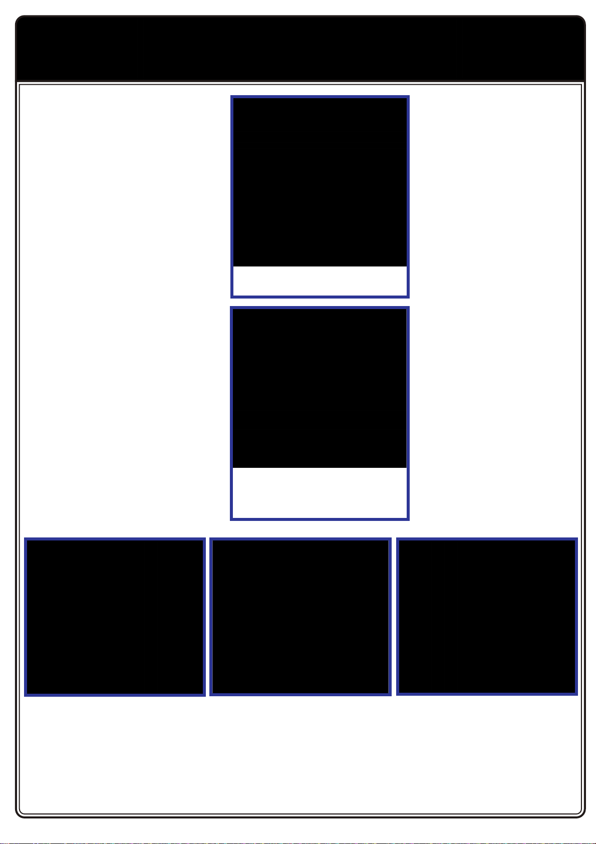
Hold down the transmitter “Bind” button
before switching the power on.
With the power on you can release the
bind button once the green ED begins to
flash to indicate the “Bind” process has
initiated.
Unless a battery powered model using
an ESC with BEC, a receiver pack
should be plugged into the VCC socket
via a suitable power switch, making sure
to check for correct polarity.
To ‘Bind’ the receiver to the transmitter
the supplied Bind Plug should be
installed channel 3/bind socket before
power is applied. The red ED should
begin to flash to indicate the ‘Bind’
process has begun, and go solid red once
‘Bind’ is complete. Now remove the ‘Bind’
plug and restart the power up procedure.
Once the ‘Bind’ process is complete, the
throttle failsafe position can be set by
pressing the button using the pointer
provided.
Mighty Thunder M nu l.qxp_MT M nu l 04/08/2017 15:13 P ge 9

10
Getting Started
Switch on transmitter. Hold vehicle clear of the ground, connect battery pack and switch on receiver. Bind the Transmitter and receiver if required.
Test the transmitter to check control of the vehicle with wheels off the ground. Start driving slowly and if the vehicle does not go straight, adjust
steering trim dial on Transmitter. For the very first run use the throttle gently, to gradually bed in the motor brushes and help the driver become
accustomed to the vehicles behaviour and controls.
PLEASE NOTE:
Although the electronics are waterproof the rest of car can be subjected to damage if running in excessively wet or submerged conditions.
After Run.
Switch off the receiver power, switch off the transmitter and lower the aerial. Disconnect the battery and remove it from the vehicle, allow it to cool
before recharging. If you have a second charged battery all ready to use, still allow the vehicle to cool slightly before continuing.
Regular maintenance.
Frequently check the whole vehicle for loose or missing fixings. Use thread lock on any replacement screws into metal threads.
Frequently check rotating parts are free from grass, string etc. that might bind their motion and over stress the motor or speed
controller. Remove the wheels occasionally and check behind the mounting hex for obstructions or anything that might have
been wrapped around the axle and caused extra drag.
Check the gear mesh frequently and remove any stones or grit from gear teeth to prevent premature wear and damage.
If the motor moves, or is removed for maintenance/exchange, the gear mesh will need to be set. Simply slacken the motor
retaining screws and adjust the motor until there is just discernable backlash between pinion and spur teeth. If the gear is too
tight or too loose the gears will be noisy and could be damaged.
Shock absorbers will wear prematurely if used in dirty dusty conditions. Replace oil and seals as required to keep a smooth dampening action.
Trouble shooting guide.
Warranty
Due to the nature of this product and potential use FTX warrants it to be free of material and workmanship defects when new. FTX will at its sole
discretion repair or replace defective components free of charge within 30 days from date of purchase. This warranty does not cover wear and tear,
crash or impact damage, modifications, component water damage failure to perform maintenance or damage from improper use. Proof of purchase
date will be required to action any warranty claims. In no case shall FTX's liability exceed the original cost of the purchased kit.
Instructions for disposal.
Environmental Protection Notes & WEEE
The crossed-out wheeled bin symbol shown here, which may be found on the product itself, in the operating instructions or on the packaging, is in accordance with the Waste Electrical and
Electronic Equipment (WEEE) Directive. Individual markings indicate which materials can be recycled and re-used. You can make an important contribution to the protection of our common
environment by re-using the product, recycling the basic materials or recycling redundant equipment in other ways.
When this product comes to the end of its useful life, you must not dispose of it in the ordinary domestic waste. any electrical items that we throw away can be repaired or recycled.
Recycling items helps to save natural resources and also reduces the environmental and health impacts that are linked with sending electrical goods to landfill. The correct method of
disposal is to take it to your local collection point for recycling electrical and electronic equipment. You can go to recycle-more.co.uk for details of locations.
Alternatively FTX can offer our customers free take-back of their WEEE on a like-for-like basis when they buy a new Electrical or Electronic product from us.
For example, if a customer bought a new radio system from us or a dealer, we would accept their old radio and prevent it going into a landfill site by disposing of it safely. Customers must
return their old WEEE item to us within 28 days of purchasing their new item.
Remove batteries from your device and dispose of them at your local collection point for batteries. If you don’t know the location of your nearest disposal centre,
please enquire at your local council office.
Short Runtime:
Battery damaged/not
charged
otor dirty or brushes worn
Drivetrain binding
Sluggish Action:
otor dirty or brushes worn
Bind in drive train
Battery running low on
power
Motor/ESC overheat:
Over-geared
Binding transmission.
Seized axle bearing.
otor binding
Motor spins but vehicle
refuses to move:
Gears damaged.
Gears loose on shaft.
Slipper clutch too loose.
Drive shaft broken or
missing.
Poor Range or fails to
operate:
Transmitter batteries low
Vehicle Battery Low.
Transmitter switched off
Transmitter/receiver aerial
not extended.
ESC switched off or battery
not connected.
Loose connectors/wires.
Water damage. odel
electronics are not
waterproof.
WEE/GB4215VX
CM DISTRIBUTION, SAXON HOUSE, SAXON BUSINESS PARK,
HANBURY ROAD, BROMSGROVE, B60 4AD.
Mighty Thunder M nu l.qxp_MT M nu l 04/08/2017 15:13 P ge 10

11
FTX Mighty Thunder Prêt à rouler
électrique 2.4GHz ltra Buggy
erci d’avoir choisi le FTX Outlaw 4x4 électrique ou le FTX
Outlaw Buggy 4x4 électrique. Ce modèle est monté
d’usine, l’électronique est pré installée et réglée pour
permettre un démarrage et du plaisir le plus
rapidement possible.
Mesures de sécurité:
• Vous êtes responsable lors de
l’évolution de ce modèle, veillez à ne
pas vous mettre en danger, à mettre
en danger le modèle ou la propriété
d’autrui.
• Ce modèle radiocommandé peut être
perturbé par d’autres sources d’onde
radio, ce qui peut entrainer la perte
momentanée du contrôle de la voiture.
• Age recommandé : 14 ans, ceci n’est pas un jouet,
ce produit n’est pas fait pour être utilisé par un enfant sans
surveillance.
Suivez consciencieusement les instructions
suivantes:
• Ne jamais évoluer avec des batteries d’émission faibles
• Toujours évoluer dans une zone dégagée, loin de la circulation et de
la foule
• Ne jamais évoluer dans une rue ou un endroit fréquenté
• Toujours garder le modèle dans son champ de vision
• Gardez hors de portée des enfants tous les composants de petite
taille, électriques ou chimiques
• Tenez le modèle hors de portée de l’eau (la rouille peut causer des
dommages irréversibles au modèle)
• Faites attention aux pièces en rotations, axes, pignons etc.
• Les débutants doivent prendre conseil auprès de personnes plus expérimentées
• Faites attention lors de l’utilisation des outils
• Attention à ne pas mettre les doigts ou d’autres parties du corps en contact avec les pièces en rotation
• Faites attention lors du transport, de la maintenance ou de la réparation, certaines pièces peuvent être coupantes.
• NE JA AIS toucher les composants tels que le moteur, le variateur ou les batteries après utilisation, ces
pièces peuvent être chaudes
• Lorsque vous changez de fréquence d’émission assurez-vous que les quartz de
fréquence sont bien positionnés (RX pour récepteur et TX pour l’émetteur)
• Toujours éteindre en premier la voiture avant l’émetteur
• Vérifiez le bon fonctionnement de la voiture les roues dans le vide (en
prenant les précautions nécessaires)
• Prolongez la durée de vie du moteur en le préservant de la
surchauffe (la durée de vie du moteur dépend aussi de
la fréquence de roulage, des changements rapide
de direction avant/arrière, des conditions de
roulage difficiles poussière/boue des utilisations
abusives tirer/pousser des objets)
Contenu:
1 Outlaw 1/10ème Prêt à rouler électrique
1 Emetteur à volant fréquence 2.4GHz
1 Chargeur : entré 240V sortie 300mA
1 Batterie 7.2V 1800mAH NI H
1 Tube d’antenne
Français
ATTENTION: lisez l’intégralité du manuel pour exploiter au mieux la voiture
et éviter des dommages mécaniques ou corporels. Ce modèle n’est pas un
jouet, il doit être manipulé avec précaution. Utilisé dans de mauvaises
conditions, ce modèle peut causer des dommages.
Ce modèle n’est pas fait pour être utilisé par un enfant sans la surveillance
directe d’un adulte.
Il est essentiel de lire et de suivre les instructions et les recommandations
de ce manuel pour entretenir et faire évoluer votre modèle dans de
bonnes conditions.
Mighty Thunder M nu l.qxp_MT M nu l 04/08/2017 15:14 P ge 11

12
Equipments requis pour la maintenance:
ATTENTION: L’utilisation d’une visseuse électric pour la maintenance pourrait
endommager l’emprunte des vis ou casser des pièces du modèle.
8 piles alcalines AA pour l’émetteur
IMPORTANT: Veuillez vérifier le serrage de chaque vis et écrous avant
l’utilisation du modèle.
Mighty Thunder M nu l.qxp_MT M nu l 04/08/2017 15:14 P ge 12

13
Mighty Thunder M nu l.qxp_MT M nu l 04/08/2017 15:14 P ge 13

14
FTX6557W Instructions ESC
Caractéristiques
Ce variateur ce règle de manière simple pour facilité l’opération. Quand vous mettez
l’interrupteur sur On il cherche automatiquement le neutre. Quand le réglage
automatique est finit le moteur bip “Do” “Re” “Mi” ce qui indique que le neutre est
réglé et que tout est prêt à fonctionner. Le variateur a 2 modes de programmes et
une protection pour les basses tensions qui peut être désactivée pour les batteries
LiPo.
Spécificités
Tension entrée: 7.2V-7.4V 2S LiPo/5-6 éléments NiMh/NiCd
Courant de sortie 45A continus
Courant de pointe Max: 340A (10 sec)
Sortie BEC: 5.6V 2A
Taille: 30 x 28 x 22mm (incluant radiateur)
Poids: 38g
Protection basses tensions: LiPo Cut-off quand tension inférieure à 6V
Protection thermique: Quand température supérieure à 90°C
Schéma câblage
Réglage
Connecter tous les fils comme sur le schéma, puis mettez votre radio sur On
(assurez-vous que les trims sont au neutre et que les paramètres par défaut pour les
radios programmable sont activés)
Mettez l’ESC sur On, et vous devez entendre “Do” “Re” “Mi”, cela indique que le
neutre est réglé et que la transmission est ok. Si le moteur continue de tourner après
que le neutre soit réglé, s’il vous plaît éteindre le variateur, et recommencer la
procédure de réglage du neutre.
Mode de fonctionnement
Pour vérifier le mode utilisé
Mettre l’ESC sur On et attendez le “Do” “Re” “Mi” qui indique que le neutre est
réglé, puis regarder la LED
Une LED qui clignote indique que le variateur est en mode normal (marche Av, frein,
marcha Arr)
Une LED fixe indique que le variateur est en mode Crawler (Marche Av avec Drag
Brake, marche Arr)
Changer le mode de fonctionnement
Changer de mode normal à mode Crawler
1. Mettre l’ESC sur On et attendre le “Do” “Re” “Mi” , la LED devra clignoter
2. Maintenez le bouton Program en bas jusqu’à entendre 2 «bips»
3. Lâcher le bouton après avoir entendu le second «Bip»
La LED deviendra fixe, le variateur est maintenant en mode Crawler
Changer de mode Crawler à mode normal
1. Mettre l’ESC sur On et attendre le “Do” “Re” “Mi”, la LED devra être fixe
2. Maintenez le bouton Program en bas jusqu’à entendre 1 «bips»
3. Lâcher le bouton après avoir entendu le «Bip»
La LED deviendra clignotante, le variateur est maintenant en mode Normal
Programmer les options de protection
Pour vérifier le statut actuel de protection
Mettre l’ESC sur On et entendre le BIP moteur
Le moteur “Bip--” + “Do” “ Re” “Mi”
Les protections basse tension et thermique sont sur OFF et le neutre et réglé.
Le moteur “Bip--Bip--” + “Do” “ Re” “Mi”
Les protections basse tension et thermique sont sur ON et le neutre et réglé.
Noter s’il vous plaît: Si vous utilisez une batterie LiPo vous devez activer la
protection tension basse. La protection basse tension sera active si la tension de
la batterie LiPo descend en dessous de 6V, cela coupera le moteur pour protéger
la batterie LiPo et éviter que sa tension descende trop bas. Si vous utilisez des
éléments NiMh ou NiCd vous devez rouler avec la protection basse tension sur
OFF car la protection basse tension n’est pas nécessaire, rouler avec la protection
ne nuira pas aux éléments mais il peut causer une coupure du variateur sans
explications.
Si la température du variateur arrive vers 90°, l’ESC peut couper pour se protéger.
Une fois la température descendu en dessous de 90° le variateur devient à
nouveau opérationnel.
Changer les fonctions de protection
1. Maintenir le bouton program et mettre l’ESC sur ON
2. L’ESC Bipera pour indiquer quel mode est réglé
Pour mettre la protection sur OFF attendre un “bip” puis lâcher le bouton
Pour mettre la protection sur ON garder le bouton enfoncé pour entendre le
second “bip” puis lâcher le bouton.
3. Une fois le bon “bip” choisi le moteur fera “Do” “Re” “Mi”
4. Mettre l’ESC sur OFF puis ON et attendre le réglage du neutre “Do” “Re” “Mi”
Votre ESC est maintenant prêt à être utilisé dans le mode sélectionné
Fonction
• Marche AV: Tirer la gâchette et la voiture avancera.
Si la voiture bouge peu, ajuster le trim (N sur la photo du transmetteur)
• Frein: permettre à la gâchette un retour au neutre puis pousser la gâchette
en avant.
• Marche Arr: Pousser la gâchette en avant et la voiture ira en arrière.
La voiture doit être stationnaire avant d’enclencher la marche arrière.
Cela protégera le variateur des actions AV/ARR excessives.
• Indicateur LED
Mode Crawler. La LED sera fixe quand la voiture ne bouge pas, elle commencera à
clignoter doucement quand la voiture bougera et clignotera de plus en plus jusqu’à
la vitesse maximale. (pareil pour marche AV et marche ARR.)
Mode Normal. la LED clignotera quand la voiture ne bouge pas, elle clignotera de
plus en plus jusqu’à ce que la voiture atteigne sa pleine vitesse, lorsque vous freinez
la LED sera fixe (pareil pour marche AV et marche ARR.)
Attention
Autant l’ESC est résistant à l’eau mais le reste du véhicule ne l’est pas. Ne pas rouler
ni submerger le modèle pendant de longues périodes cela peut causer des
dommages irréversibles.
Il est dangereux de toucher le moteur après utilisation car il est chaud et le radiateur
aussi, risques de brûlures.
Le variateur est compatible avec les batteries LiPo mais vous devez vous assurer
que le mode de protection basses tensions est sur On comme détaillé dans le
paragraphe “ Changer les fonctions de protection”
Mighty Thunder M nu l.qxp_MT M nu l 04/08/2017 15:14 P ge 14

15
RÉGLAGE DE L’ENSEMBLE RADIO 2.4G
1) INTRODUCTION.
erci d’avoir choisi cet ensemble radio
Etronix 2.4G. Cette radio a été
dessinée pour un usage terrestre mais
elle peut aussi être utilisée pour un
bateau 2 voies.
Si vous utilisez ce produit pour la 1ère
fois, veuillez lire attentivement les
instructions suivantes. Faites
spécialement attention aux instructions
de cette notice pour obtenir une
utilisation optimale.
2) UTI ISATION.
Si vous rencontrez quelconque difficulté
référez vous au manuel et si le
problème persiste contactez votre
détaillant pour demander conseil.
3) SECURITE.
Si vous ne lisez pas et ne comprenez
pas correctement le manuel vous
risquez d’endommager
irrémédiablement votre radio, votre
voiture ou encore une autre personne.
4) GUIDE D’UTI ISATION.
NE JAMAIS conduire de nuit, par
mauvais temps, lors de tempête, d’éclairs ou de pluie etc.
NE JAMAIS conduire dans une rue entre des voitures, des
personnes des enfantes ou encore des animaux
TOUJOURS vérifier la réponse correcte de votre voiture avant de
partir. Si celle-ci ne répond pas correctement, veuillez inspecter
l’installation électronique et vous reporter au manuel.
ASSUREZ-VOUS que la commande de gaz est au neutre avant de
mettre en marche votre radio.
NE JAMAIS arrêter la radio avant la réception de la voiture.
5) ENTRETIEN DE A BATTERIE.
Si votre radio ou votre récepteur est alimenté par des batteries
rechargeables, vérifiez toujours leurs chargements avant de commencer
l’utilisation. Une perte de contrôle peut être facilement produite si les
batteries ne sont pas adaptées ou correctement chargées. Lorsque vous
chargez des batteries NI H ou NICD veuillez toujours utiliser un
chargeur approprié. Ne jamais essayer de recharger une batterie
endommagée. Si lors de l’utilisation ou du chargement une batterie
montre des signes de surchauffe ou de faiblesse veuillez la remplacer
immédiatement.
6) CHARGE DE A RADIO.
Connectez un chargeur spécial à la prise murale puis
connectez la prise de charge à l’arrière de la radio.
Lorsque la charge est complète débranchez l’appareil.
Ne pas utiliser de piles alcalines sèches
(Chargeur et câble de charge disponible en option)
Installez chaque pile 1.5V (AA) dans la radio et
refermez le couvercle
Etronix pulse EX2 sport 2 voies 2.4G à volant
Etronix Pulse EX2 Sport
2 Channel 2.4GHz Steer Wheel Transmitter
7) CARACTERISTIQUES
Nombre de Voies : 2
Fréquences : 2.4GHz
Puissance d’émission : 2dbm
Type : Digital
Alimentation : 12V ( 8* 1.5AA)
Voltage d’alerte : 9V
Port de charge : 5mm (chargeur non inclus)
Port DSC : 3.5mm (option : pour une adaptation
USB)
Antenne : 120 mm
Poids : 328 g
Taille : 159*99*315 mm
Couleur : Noire
Certification : CE, FCC
Mighty Thunder M nu l.qxp_MT M nu l 04/08/2017 15:14 P ge 15

16
8) KEY TO TRANSMITTER FEATURES.
a) Antenne pliable et rotative
b) Volant
c) gâchette de gaz
d) cache de protection des réglages.
e) Cache Batterie
f) Prise DSC (pour simulateur/ cordon USB non fournit)
g) Port de charge
h) bouton d’inversion de la direction
i) Bouton d’inversion des Gaz
j) umière de voltage (rouge)
k) umière de voltage (vert)
l) Bouton de bind (couplage récepteur / radio)
m) Trim de direction
n) Trim de gaz
o) bouton de limitation de débattement de direction.
9) FONCTIONS DE A RADIO.
Dépliez l’antenne de la radio (A) pour une portée maximum. Notez que
l’antenne est mobile pour vous assurez un stockage facile.
La direction (B) est sur la voie N 1, si vous tournez le volant dans le
sens antihoraire la voiture doit tourner les roue vers la gauche et vise
versa. (La voiture se regarde dans le sens de la marche) Si ce n’est
pas le cas, inversez la direction à l’aide du bouton (H)
Les gaz/frein sont sur la voie 2 ; lorsque vous ramenez la gâchette vers
’antenne se plie pour un meilleur stockage. Mais elle se
déplie et est positionnable pour maximiser la portée de la
radio
Mighty Thunder M nu l.qxp_MT M nu l 04/08/2017 15:14 P ge 16

17
vous, la voiture doit accélérer et vice versa, si
ce n’est pas le cas utilisez le bouton (I).
Ouvrez le couvercle (D) vous trouverez de
nombreux réglages utiles, poussez
l’interrupteur vers la gauche sur la position
ON, les LED Rouge et Verte indiquent le
niveau des batteries.
Si les batteries sont vieilles et passent en
dessous de 9V la LED verte clignote et vous
informe que la portée va être limitée, vous
risquez de perdre le contrôle de votre modèle. Changez ou rechargez
vos batteries. Si votre modèle n’avance pas bien droit ajustez la
direction à l’aide du trim de direction ( ) si votre modèle ne reste pas
en place alors que la gâchette est au neutre ajustez avec la trim de gaz
(N).
Le bouton (o) contrôle le débattement total des du servo de direction.
Vérifiez et ajustez la direction pour vous assurer que le servo ne force
pas en position maximum. De plus si le véhicule semble tourner trop
violement pour vous, vous pouvez vous servir de ce réglage pour calmer
la réaction du modèle en réduisant le rayon de braquage de la voiture.
Si le servo est correctement connecté à la
réception mais que la voiture ne tourne pas.
Vérifiez les branchements mais vérifiez aussi
que le bouton (O) n’est pas mis à 0.
10) CARACTERISTIQUES DU
RECEPTEUR.
Nombre de voies : 3
Failsafe (sécurité) : réglage de la position
de sécurité
Fréquence : 2.4G
Modulation : GFSK
Sensibilité : 1024
Sensibilité du récepteur :
100 dbm
Alimentation : de 4.5 à 6 V
Poids : 5 G
Antenne : 176 mm
Taille : 37.6*22.3*13 mm
Couleur: noire
Certification : CE, FCC
11) INSTA ATION DU
RECEPTEUR .
Le récepteur doit être monté correctement à
plat sur votre voiture. Si possible dans un boîtier le protégeant de
l’humidité, des projections et de la poussière. Installez l'antenne aussi
loin que possible de tout appareil électronique ou pièce en métal, avec
au moins la dernière moitié du fil d'antenne dans un tube d’antenne
positionné à la verticale pour maximiser la portée.
Pour les modèles alimentés à l’essence, reliez la batterie au récepteur
(en respectant la polarité) dans la prise marquée "VCC".
Pour les véhicules électriques équipés d'un variateur, alimentez la radio
(via le BEC). Branchez le variateur sur le canal 2. Le troisième canal
n'est pas utilisé sur cette radio. La 3ème voie sert au bind (couplage
récepteur/ radio) ; après le couplage cette voie peut être utilisée pour
alimenter un ventilateur ou un transpondeur personnel (puce de
comptage pour compétition).
Quand la gâchette de gaz est au neutre, le
modèle doit être immobile. Si ce n’est pas le
cas ajustez avec le trim de Gaz (N).
Ramenez la gâchette vers vous la voiture
doit accélérer et vice versa, si ce n’est pas le
cas utilisez le bouton (I).
Poussez la gâchette la voiture doit freiner puis
reculer et vice versa, si ce n’est pas le cas
utilisez le bouton (I).
Mighty Thunder M nu l.qxp_MT M nu l 04/08/2017 15:14 P ge 17

18
12) COUP ER A RECEPTEUR ET A
RADIO (BIND)
Pour vous assurer qu’une seule radio puisse
contrôler votre récepteur vous devez les coupler
ensemble. Le couplage est aussi appelé « bind ».
Apres cette opération le tout communiquera
ensemble grâce à un code commun. Il y a un cordon
« bind » fourni avec le récepteur, veuillez l’insérer
dans la troisième voie du récepteur avant de le
mettre sous tension. La LED rouge sur le récepteur
va commencer à clignoter pour vous signaler que
l’opération de « bind » est en cours. Enfoncez
maintenant le bouton « bind » de la radio (L) avant
d’allumer celle-ci.
La LED verte sur la radio va clignoter ; la LED rouge
du récepteur va s’arrêter puis se rallumer et se
stabiliser ce qui signifie que l’opération de bind s’est
terminée correctement. Avant de rouler avec le
modèle éteignez la radio et le récepteur, retirez le
cordon « bind » pour terminer l’opération. Vous
pouvez maintenant rallumer votre modèle
normalement (Radio en premier puis la réception) si
la LED rouge ne se fixe pas cela signifie que
l’opération de Bind a échouée. Dans ce cas veuillez
recommencer l’opération de bind depuis le début.
SI C’EST votre première utilisation, rappelez vous
que vous devez contrôler l’ajustement des neutres et
les corriger si besoin. Il est aussi recommandé de
régler la Failsafe (position de sécurité).
13) REG AGE DU FAI SAFE
(POSITION DE SECURITE).
Ce récepteur Etronix intègre un système de
protection appelé fail safe. Si le modèle va au-delà
des limites du signal ou si celui-ci est interrompu, le
dispositif de sécurité (fail safe) met automatiquement les gaz (voie 2) à
une position prédéfinie à condition que le récepteur soit toujours
alimenté.
Veuillez mettre en place le dispositif de
sécurité avant la première utilisation.
Allumez la radio puis alimentez le
récepteur. Un pointeur est fourni (sur la
prise de Bind), ce pointeur doit être utilisé
pour maintenir le bouton fail safe intégré
sur le récepteur pendant trois secondes
jusqu'à ce que la LED rouge clignote
plusieurs fois pour indiquer la réussite du
réglage de la position de sécurité. (La
position de sécurité définie est celle de la
gâchette lors que vous enfoncez le bouton
fail safe)
aintenant, chaque fois que le récepteur
ne reçoit pas de signal il corrigera seule la
position des Gaz. Pour tester le dispositif
de sécurité, allumez votre modèle, les
roues en l’air appliquer un peu de gaz puis
éteignez la radio. Rapidement, le servo de
gaz (ou régulateur de vitesse) devrait
s’être repositionné à la position de
sécurité. On définit généralement la
position de sécurité au neutre de sorte
qu’en cas de perte de signal le véhicule
ralentisse doucement puis s’arrête.
Remarque: - si le récepteur est à nouveau
couplé à l'émetteur pour une raison
quelconque, la position de sécurité est
perdue si elle devra être remise à zéro à
nouveau.
Merci d'avoir choisi Etronix.
’Utilisation des avantages de la
technologie 2.4GHz vous libère des
interférences et des problèmes des
radios à quartz. Utilisée correctement et
en observant les informations contenues dans ce manuel, nous
sommes sur que la radio Pulse EX2 Sport vous donnera plaisir et
performance.
Maintenez enfoncé le bouton “Blind”
avant de mettre sous tension votre radio.
Quand vous avez allumé votre radio vous
pouvez relâcher le bouton “blind”, la ED
verte va se mettre à clignoter pour vous
indiquer que l’opération de couplage est
en cours.
Sauf si votre modèle possède un
variateur avec BEC alimentez votre
récepteur par la voie 2. Si c’est pack de
récepteur qui alimente le récepteur, Il
doit être branché dans la prise VCC en
prenant soin de vérifier la polarité.
Pour coupler votre récepteur et votre
radio installez le cordon bind sur la voie
Bind avant d’allumer votre récepteur.
Allumez la radio en maintenant enfoncé le
bouton bind, quand la ED du récepteur
se stabilise la procédure est terminée.
Eteignez l’ensemble et enlevez le cordon
Bind, votre ensemble est prêt à
fonctionner.
Quand la procédure de Bind est terminée
vous pouvez configurer la position de
sécurité en enfonçant le bouton Failsafe
avec le pointeur.
Mighty Thunder M nu l.qxp_MT M nu l 04/08/2017 15:14 P ge 18

19
En route
Dépliez l’antenne passez sur ON la radio, tenez la voiture les roues en l’air, connectez les batteries puis allumez la voiture. Testez
la voiture les roues en l’air pour vous assurer de son bon fonctionnement puis poser la voiture au sol et testez doucement son
fonctionnement. Si la voiture ne va pas droit ajustez le trim de direction. Lors de la première utilisation accélérez doucement pour
vous familiariser avec l’utilisation de la voiture.
S'IL VO S PLAÎT NOTE
IMPORTANT : Veuillez noter que ce véhicule n'est pas étanche et ne doit pas être exécuté dans des conditions mouillées ou humides
où l'humidité pourrait pénétrer dans l'électronique.
Arrêt du modèle
Eteignez l'interrupteur du récepteur (voiture), éteignez ensuite l'interrupteur de la radio-commande puis repliez l'antenne.
Débranchez ensuite les batteries et retires celles-ci de la voiture.
Laissez les batteries refroidir avant des les recharger. Si vous possédez une seconde batterie déjà chargée, laissez le véhicule
refroidir quelques minutes avant d'installer cette deuxième batterie.
Entretien.
Vérifiez souvent que des vis ne sont pas absentes ou dévissées. Utilisez du frein filet pour
tout remplacement de vis dans du métal. Vérifiez que les pièces en rotation sont bien libres
(herbe , pierre etc ). Si ces pièces ne sont pas libres cela peut les endommager ou encore
user le moteur ou le variateur. Enlevez les roues et vérifiez que rien ne s’est glissé derrière
l’hexagone de roue et n’empêche une bonne liberté de la transmission. Si le moteur bouge
ou est enlevé pour entretien/échange, vous devez refaire le réglage de l’entre dents. Pour
cela devisez les vis moteur et bougez-le jusqu'à avoir un petit jeu fonctionnel entre le pignon
moteur et la couronne. Si ce réglage est mal fait la transmission peut être bruyante mais
aussi s’endommager. Les amortisseurs vont s’user plus vite si vous roulez dans des
conditions poussiéreuses, remplacez l’huile ainsi que les joins pour conservé un bon
amortissement.
Solutions aux problèmes:
Garantie
De part la nature de ce produit et l’utilisation potentiel, FTX garanti qu’il n’a pas défaut lorsque le modèle est neuf. FTX s’engage à
réparer ou remplacer les composants défectueux gratuitement dans un délai de 30 jours à compter de la date d'achat. Cette
garantie ne couvre pas l'usure normale, l’accident ou l’impact, les modifications, les dégâts des eaux (appareil n'étant pas étanche)
le manque d'entretien ou de dommages causés par une mauvaise utilisation. La preuve de la date d'achat sera nécessaire lors des
réclamations de garantie.
Instructions pour la mise au rebut.
Ce produit ne doit pas être jeté avec les autres déchets. L’utilisateur doit le déposer dans un point de collecte et de recyclage des
déchets. Pour plus d'informations sur l'endroit où vous pouvez déposer vos déchets, s'il vous plaît contacter votre municipalité, ou
bien où vous avez acheté le produit.
Durée de roulage très
courte:
Les batteries sont
endommagées ou mal
chargées.
Le moteur est sale ou
les charbons usés.
Vitesse lente:
Le moteur est sale ou
les charbons usés.
Le moteur ou le variateur
surchauffe:
La transmission n’est
pas libre
Le moteur est
endommagé.
Le moteur tourne mais la
voiture n’avance pas:
La transmission est
abîmée.
Le slipper est desserré,
un cardant est cassé ou
manquant.
ne portée courte ou
aucun contrôle de la
voiture:
Les piles de la
télécommande sont
vides, les batteries de la
voiture sont vides,
l’antenne n’est pas
dépliée, un fil est
débranché,
l’électronique est
endommagée.
WEE/GB4215VX
CM DISTRIBUTION, SAXON HOUSE, SAXON BUSINESS PARK,
HANBURY ROAD, BROMSGROVE, B60 4AD.
Mighty Thunder M nu l.qxp_MT M nu l 04/08/2017 15:14 P ge 19

20
Parts Diagram
Mighty Th nder Man al.qxp_MT Parts Man al 04/08/2017 15:17 Page 20
Table of contents
Languages:
Other FTX Motorized Toy Car manuals

FTX
FTX HOOLIGAN JNR User manual

FTX
FTX Buggy Vantage 2.0 Brushed RTR User manual

FTX
FTX Kanyon User manual

FTX
FTX Surge MT User manual

FTX
FTX OUTBACK MINI 2.0X User manual

FTX
FTX OUTLAW User manual

FTX
FTX OUTBACK GEO User manual

FTX
FTX BANZAI FTX5529 Manual

FTX
FTX OUTBACK MINI X 6IXER User manual

FTX
FTX Crawler Mini Outback 3.0 Ranger 1:24 RTR User manual
Popular Motorized Toy Car manuals by other brands

Power Wheels
Power Wheels DODGE 73520 owner's manual

Vaterra
Vaterra Halix RTR Monster Truck owner's manual

Kid Galaxy
Kid Galaxy 10318 quick start guide

Jamara
Jamara 405024 Instruction

Canon
Canon Creative Park Classic Car 05 Series Assembly instructions

Associated Electrics
Associated Electrics R10 instruction manual