FTX Kanyon User manual

1
FTXMRManual.indd 1FTXMRManual.indd 1 27/04/2022 09:4727/04/2022 09:47

2
FTX KANYON 1/10TH XL SCALE 4WD READY-TO-RUN
RESCUE TRAIL VEHICLE
Congratulations on your purchase of the ‘FTX Kanyon
Mountain Rescue 1/10th XL Scale 4wd Ready-To-Run
Trail Vehicle’.
This 1/10th XL scale model has been factory assembled and all electrics installed
and set up to make it the easiest possible introduction to the sport of driving RC
cars.
Safety Precautions and Warnings
• You are responsible for operating this model such that it does not endanger
yourself and others, or result in damage to the product or the property of
others.
• This model is controlled by a radio which is possibly subject to interference
which can cause momentary loss of control so it is advisable to
always keep a safe distance to avoid collisions or injury.
• Age Recommendation: 14 years or over. This is not a toy. This product is not
intended for use by children without direct adult supervision.
Carefully follow these directions and warnings,
plus those of any additional equipment associated
with the use of this model, fuel, starting equipment,
engine, radio etc.
• Never operate your model with low transmitter batteries.
• Always operate your model in an open area away from cars, trafc or people.
• Never operate the model in the street or in populated areas.
• Do NOT touch equipment such as the engine heatsink head and exhaust pipe,
immediately after using your model because they can generate high
temperatures.
• Always keep the vehicle in direct line of sight, you cannot control what you
cannot see!
• Keep all chemicals, small parts and anything electrical out of the reach of
children.
• Although the model includes waterproof servos and receiver, the model and
engine are not suited to extensive running in wet weather conditions.
Long term damage can occur to the model and particularly the engine if run in prolonged wet conditions.
• Avoid injury from high speed rotating parts, gears and axles etc.
• Novices should seek advice from more experienced people to operate the
model correctly and meet its performance potential.
• Exercise caution when using tools and sharp instruments.
• Do not put ngers or any objects inside rotating and moving parts.
• Take care when carrying out repairs or maintenance as some parts may be
sharp.
• Always turn on your transmitter before you turn on the receiver in the car.
Always turn off the receiver before turning your transmitter off.
• Keep the wheels of the model off the ground, and keep your hands away from
the wheels when checking the operation of the radio equipment or engine
set-up.
• Prolong engine life by following the engine set-up and guidelines outlined
within the manual.
Contents:
• FTX 1:10th XL Ready-To-Run 4WD Trail Vehicle
• Transmitter: 2.4GHz Steerwheel.
• Charger: USB 600mA Charger
• Battery: 7.2V 1800mAh NiMH
WARNING:
Read the ENTIRE instruction manual to become familiar with the features
of the product before operating. Failure to operate the product correctly
can result in damage to the product, personal property and cause serious
injury.
This is NOT a toy and must be operated with caution and common
sense. Failure to operate this product in a safe and responsible
manner could result in damage, injury or damage to other property.
This product is not intended for use by children without direct
adult supervision.
It is essential to read and follow all the instructions and warnings
in the manual, prior to assembly, set-up or use, in order to operate
correctly and avoid damage or serious injury.
FTXMRManual.indd 2FTXMRManual.indd 2 27/04/2022 09:4727/04/2022 09:47

3
REQUIRED EQUIPMENT FOR OPERATION
• 4 pcs AA Alkaline Batteries
FTXMRManual.indd 3FTXMRManual.indd 3 27/04/2022 09:4727/04/2022 09:47

4
FIRST TIME SETTING UP OF THE BRUSHED ESC
FTXMRManual.indd 4FTXMRManual.indd 4 27/04/2022 09:4727/04/2022 09:47

5
FAMILIARIZING YOURSELF WITH YOUR 2.4GHZ RADIO SYSTEM
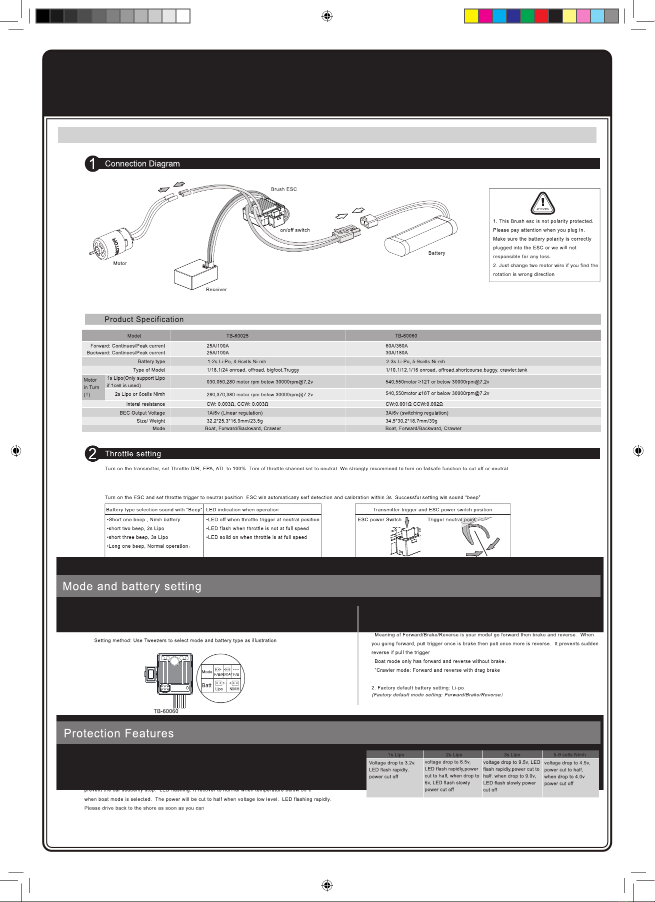
SYSTEM FEATURES
• 2.4ghz FHSS
• Receiver 3mS response time
• 400-500m range
• Failsafe feature
• Transmitter voltage range 6V-7.4V (support 1s-2s)
automatic indentication of voltage, low voltage warning: 7.4V/4.8V
• Receiver voltage range: 3.3V-7.4V, working current 30mA, supports high voltage servos.
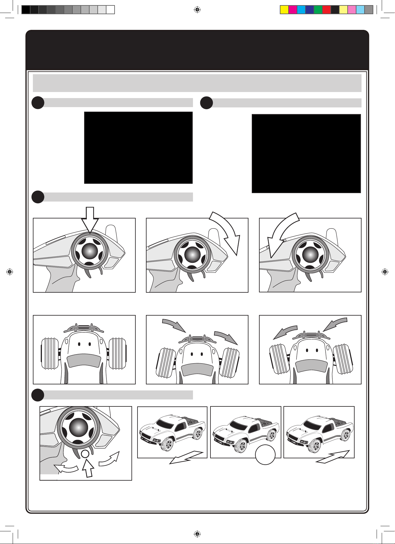
MENU SETTING:
To enter the program mode:
1. With the power o, move the steering wheel to its
maximum forward position, hold this position and
power on the transmitter.
2. The blue LED indicator will illuminate and remain solid,
return the steering wheel to its neutral position, and
press the CH3 button.
The LED indicator will now ash blue rapidly, indicating that
you have entered program mode.
PROGRAM THE TRANSMITTER:
Once in program mode, the travel end points of CH1 and
CH2 can be congured:
1. Rotate the steering wheel to its desired maximum
position in both directions, returning it to its neutral
position.
2. Pull/push the throttle trigger to its desired maximum
position, forwards and backwards, returning it to its
neutral position.
3. Once the steering wheel and throttle trigger have been
in their neutral positions for 3 seconds, press the CH3
button once to save these settings.
4. The LED indicator will now ash steady blue, and the
transmitter will operate normally.
(Default factory settings are maximum travel for CH1
and CH2).
IF CH3 AND CH4 REQUIRE PROGRAMMING:
When in program mode, CH1 and CH2 EPA dials on the
control panel can be used to set the travel of CH3 and CH4
respectively.
Once in program mode:
1. Rotate the steering wheel to its desired maximum
position in both directions, returning it to its neutral
position.
2. Pull/push the throttle trigger to its desired maximum
position, forwards and backwards, returning it to its
neutral position.
3. Rotate and position the CH1 dial to congure the
desired travel for CH3.
4. Rotate and position the CH2 dial to congure the
desired travel for CH4.
5. Once all end points and travel settings have been
adjusted, press the CH3 button to save these settings.
6. The LED indicator will now ash steady blue, and the
transmitter will operate normally.
Note: Each time program mode is initiated, all settings are
erased and must be recongured.
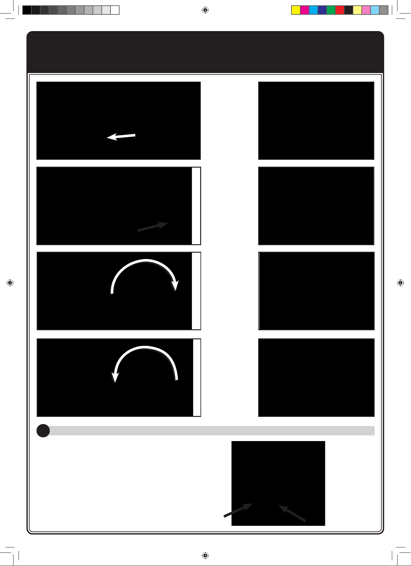
MODE SWITCH:
To switch from ‘Normal Mode’ to ‘Mixed Mode’:
1. Push the throttle trigger to the maximum forward
position and power on the transmitter. The LED
indicator will rapidly ash blue.
2. Pull the trigger backwards to its maximum position, and
release back to its neutral position. The LED indicator
will now ash steady red/yellow to indicate that ‘Mixed
Mode’ is enabled.
To return to normal mode, repeat the above process ^.
The LED indicator will ash steady blue to indicate that
‘Normal Mode’ is enabled.
MIXED MODE (RC TANK OPERATION):
Mixed mode will allow the connection of two ESC and
motor combinations, to channel 1 and channel 2 of the
receiver. With mixed mode is enabled, when the throttle
trigger (CH2) is pulled backwards or pushed forwards,
this will control the forward or backward movement of the
model. Each connected motor will operate at a continuous
speed, however, the speed of each individual motor can
be adjusted by rotating the steering wheel (CH1) in either
direction. See diagrams.
In mixed control mode, throttle direction, trim, neutral and
end points can all be congured separately using the dials
and switches on the control panel.
Binding Process
1. Press the receiver button and the LED indicator will
ash fast indicating it is entering bind mode.
2. Turn on transmitter. The receiver will automatically
look for the nearest transmitter signal.
3. Once binding is successful the LED will stop
ashing and remain on.
LED Light
1. Normal use: blue light ashes
slowly.
2. Mixed direction for Tank mode:
Red light is always on.
3. Low voltage warning: Yellow
light ashes slowly.
4. Entering second menu level
mode: Blue/Red light ashes
quickly.
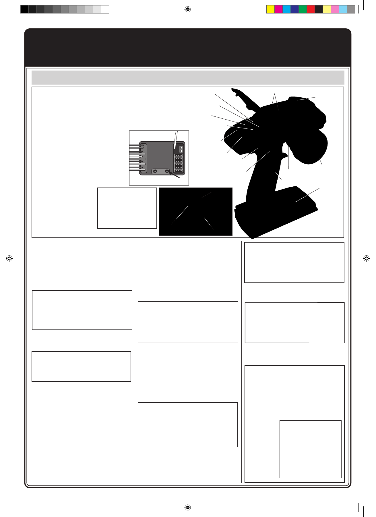
Channel 5 for winch forward/reverse
Steering reverse switch
Throttle reverse switch
Steering Trim dial
Throttle Trim dial
Steering Dual/
Rate dial
Throttle Dual/Rate dial
Optional channel Throttle
Antenna
Steering Wheel
Battery compartment
Channel 3
On/Off
LED Light
Simulator/
PPM interface USB
Connection
TRANSMITTER BATTERY INSTALLATION
1. Press down on the battery cover and slide in the
direction of the arrow to remove.
2. Install 4 AA alkaline cells (or Ni-Cd, or Ni-MH)
as indicated inside the battery compartment.
Make sure to match the inside polarity the (+ and
-) as shown in the battery compartment or the
transmitter will not function.
3. Install the battery cover in place and slide to close.
WARNING:
Improper
installation of
transmitter
batteries can
cause serious
damage to
your system.
Internal battery
socket for 2S Li-Po.
Bind Button
LED light
Ch 1 Route setting Ch 2 Route Setting Submit Key
2. Turn On 1. Forward to the
Maximum
4. Press the
Ch 3
button
3. Release the
Wheel
Submit
Key
Ch 2
adjustment
for Ch 4
Ch1
adjustment
for Ch3
1. Push
trigger forward
maximum
3. After the LED ashes pull
the trigger all the way back
then release. The LED will
change colour.
2. Turn On
ESC
Receiver
FTXMRManual.indd 5FTXMRManual.indd 5 27/04/2022 09:4727/04/2022 09:47

6
• Always store your model with the battery pack unplugged and
removed.
• Always charge your battery away from the vehicle.
The included USB charger will take approximately 3 hours to
charge a discharged 1800mAh battery.
• When charging the Red LED will be solid.
• When the battery is fully charged the Green LED will be solid.
winch
car LED set
steering servo (9kg)
2-speed H/L servo (3kg)
ESC
Receiver
RECEIVER & SPEED CONTROL WIRING DIAGRAM
CHARGING
FTXMRManual.indd 6FTXMRManual.indd 6 27/04/2022 09:4727/04/2022 09:47

7
RUNNING YOUR CAR
1. TURNING ON THE RECEIVER OF YOUR CAR 2. TURN ON THE RADIO CONTROLLER
3. CHECK STEERING PERFORMANCE
The ESC
Receiver switch
is located under
the side plate
of the model.
Switch on the
ESC/Receiver
Switch as
shown in the
picture.
Switch on the
power switch
on the radio
controller.
Your radio is
bound with
your car
automatically.
CENTRE TURN RIGHT TURN LEFT
1. To keep the car running straight,
keep the streering wheel centered.
2. Turn the steering wheel to the right
to allow the car to right.
3. Turn the steering wheel to the left
to allow the car to turn to the left.
4. CHECK TRIGGER RESPONSE
PLEASE NOTE: THE MODEL SWITCHES BETWEEN
FORWARD AND REVERSE INSTANTLY FOR SLOW SPEED
MANEOUVABILITY. EXCESSIVE USE OF THIS FEATURE
CAN CAUSE TRANSMISSION AND ESC DAMAGE.
STOP!
A. B.
A. Pull the trigger back to accelerate, release it to decelerate.
B. To stop running your car, release the trigger to neutral.
C. Pushing the trigger forward activates reverse.
PULL TRIGGER BACK
CENTRE
PUSH
TRIGGER
FORWARD
C.
FTXMRManual.indd 7FTXMRManual.indd 7 27/04/2022 09:4727/04/2022 09:47

8
RUNNING YOUR CAR
5. TUNING THE STEERING TRIM
STEERING TRIM DIAL
Gently pull the trigger to allow your car to run slowly.
Meantime, tune the steering trim to allow the front
wheels to be aligned by rotating the dial.
STEERING
6. TUNING THE THROTTLE TRIM
7. TO TUNE THE STEERING AND THROTTLE DUAL RATE CONTROL
THROTTLE TRIM DIAL
Throttle Trim is used to set the idle speed of the car,
by rotating the dial.
THROTTLE TRIM
STEERING D/R
STEERING D/R DIAL
The D/R controls the amount of servo travel. You should
adjust this to give maximum steering without any extra
strain on the servo.
Set it to minimum rst and then slowly adjust until full
steering is achieved.
THROTTLE D/R
With this dial you can adjust the the maximum power output from your speed control.
8. STEERING/THROTTLE REVERSE
STEERING REVERSE:
To reverse the direction of servo travel for steering (CH1).
THROTTLE REVERSE:
Allows you to electronically switch the direction that the motor operates in
relation to the throttle trigger. For example, if you pull the throttle trigger to
accelerate forward but the model goes in reverse, ip the Throttle Reverse
switch to make the model accelerate forward.
FTXMRManual.indd 8FTXMRManual.indd 8 27/04/2022 09:4727/04/2022 09:47

9
Use the 3rd channel to control the 2-speed High/Low servo. Insert the servo connector into the 3rd channel on the receiver. Make sure polarity is correct. The pin on the
left side of the receiver is the signal pin, the middle pin positive and the right side is negative.
Press the Ch3 button on the transmitter for the servo operated high or low speed. When in low speed the button LED light will be ON.
In high speed the LED light will be OFF.
Note: The voltage output of the receiver is 5V so the LED lights used must support a voltage of 5V, or 6V. The LED bulb has to be connected to the receiver correctly.
Make sure your LED lights come with a JST or similar connector suitable for receiver. Make sure the polarity is correct before connecting the LED lights.
TW0-SPEED FUNCTION
High - Low
Ch3 button
The Ch4 is a slide switch that has
3 positions for different LED light
functions.
Connect wires as per their tag:
L to L, R to R, S to S and F to F.
Pay attention to the polarity.
Wire colour most be same when
connecting to each connector. E.G.
black aligned with black, yellow
aligned with yellow.
1. DETAILS FOR CONNECTING CAR LED LIGHT WIRES TO RECEIVER WIRES.
2. LED LIGHTING FUNCTIONS.
slide switch to right
Slide the Ch4 switch all the way
to the right for the roof lamps and
headlights to be xed on.
Slide the Ch4 to the centre
position for the roof lamps and
headlights to be in ashing
mode.
slide switch to centre
LED LIGHTS CONNECTION AND FUNCTIONS
FTXMRManual.indd 9FTXMRManual.indd 9 27/04/2022 09:4727/04/2022 09:47

10
3. WINCH CONTROL.
Press the right button on the transmitter to pull the winch cable out. Release the button and
the winch motor will stop.
Press the left button on the transmitter to retract in the winch cable. Release the button and
the winch motor will stop.
Note: Always keep the cable straight to avoid knotting when pulling or retracting.
Right button - release
Left button - retract
slide switch to left
Slide the Ch4 switch
all the way to the left
position for the roof
lamps and headlights
to be turned off.
Push the trigger
forward to brake/
reverse for rear red
light to come on.
Turn steering wheel
clockwise for right
indicator lights to
ash front and rear.
Turn steering wheel
clockwise for left
indicator lights to
ash front and rear.
FTXMRManual.indd 10FTXMRManual.indd 10 27/04/2022 09:4727/04/2022 09:47

11
Getting Started
Switch on transmitter. Hold vehicle clear of the ground, connect battery pack and
switch on receiver. Bind the Transmitter and receiver if required.
Test the transmitter to check control of the vehicle with wheels off the ground.
Start driving slowly and if the vehicle does not go straight, adjust steering trim dial
on Transmitter. For the very rst run use the throttle gently, to gradually bed in the
motor brushes and help the driver become accustomed to the vehicles behaviour
and controls.
PLEASE NOTE:
Although the electronics are waterproof the rest of car can be subjected to damage
if running in excessively wet or submerged conditions.
After Run.
Switch off the receiver power, switch off the transmitter and lower the aerial.
Disconnect the battery and remove it from the vehicle, allow it to cool before
recharging. If you have a second charged battery all ready to use, still allow the
vehicle to cool slightly before continuing.
Regular maintenance.
Frequently check the whole vehicle for loose or missing xings. Use thread lock on
any replacement screws into metal threads.
Frequently check rotating parts are free from grass, string etc. that might bind
their motion and over stress the motor or speed controller. Remove the wheels
occasionally and check behind the mounting hex for obstructions or anything that
might have been wrapped around the axle and caused extra drag.
Shock absorbers will wear prematurely if used in dirty dusty conditions. Replace oil
and seals as required to keep a smooth dampening action.
Warranty
Due to the nature of this product and potential use FTX warrants it to be free
of material and workmanship defects when new. FTX will at its sole discretion
repair or replace defective components free of charge within 30 days from date of
purchase. This warranty does not cover wear and tear, crash or impact damage,
modications, component water damage failure to perform maintenance or damage
from improper use. Proof of purchase date will be required to action any warranty
claims. In no case shall FTX’s liability exceed the original cost of the purchased kit.
SHORT RUNTIME:
Battery damaged/not
charged
Motor dirty or brushes worn
Drivetrain binding
SLUGGISH ACTION:
Motor dirty or brushes worn
Bind in drive train
Battery running low on
power
MOTOR/ESC OVERHEAT:
Over-geared
Binding transmission.
Seized axle bearing.
Motor binding
MOTOR SPINS BUT VEHICLE
REFUSES TO MOVE:
Gears damaged.
Gears loose on shaft.
Drive shaft broken or
missing.
POOR RANGE OR FAILS TO
OPERATE:
Transmitter batteries low
Vehicle Battery Low.
Transmitter switched off
Transmitter/receiver aerial
not extended.
ESC switched off or battery
not connected.
Loose connectors/wires.
Instructions for disposal.
Environmental Protection Notes & WEEE
The crossed-out wheeled bin symbol shown here, which may be found on the
product itself, in the operating instructions or on the packaging, is in accordance
with the Waste Electrical and Electronic Equipment (WEEE) Directive. Individual
markings indicate which materials can be recycled and re-used. You can make an
important contribution to the protection of our common environment by re-using
the product, recycling the basic materials or recycling redundant equipment in
other ways.
When this product comes to the end of its useful life, you must not dispose of it
in the ordinary domestic waste. Many electrical items that we throw away can
be repaired or recycled. Recycling items helps to save natural resources and
also reduces the environmental and health impacts that are linked with sending
electrical goods to landll. The correct method of disposal is to take it to your local
collection point for recycling electrical and electronic equipment. You can go to
recycle-more.co.uk for details of locations.
Alternatively FTX can offer our customers free take-back of their WEEE on a like-
for-like basis when they buy a new Electrical or Electronic product from us.
For example, if a customer bought a new radio system from us or a dealer, we
would accept their old radio and prevent it going into a landll site by disposing
of it safely. Customers must return their old WEEE item to us within 28 days of
purchasing their new item.
Remove batteries from your device and dispose of them at your local collection
point for batteries. If you don’t know the location of your nearest disposal centre,
please enquire at your local council ofce.
Trouble shooting guide.
CML Distribution, Saxon House, Saxon Business Park, Hanbury Road,
Bromsgrove, B60 4AD. WEE/GB4215VX
CML
FTXMRManual.indd 11FTXMRManual.indd 11 27/04/2022 09:4727/04/2022 09:47

12
EXPLODED DIAGRAM PARTS LISTING
FTXMRManual.indd 12FTXMRManual.indd 12 27/04/2022 09:4727/04/2022 09:47

13
EXPLODED DIAGRAM PARTS LISTING
FTXMRManual.indd 13FTXMRManual.indd 13 27/04/2022 09:4727/04/2022 09:47

14
FTXMRManual.indd 14FTXMRManual.indd 14 27/04/2022 09:4727/04/2022 09:47

15
EXPLODED DIAGRAM PARTS LISTING
FTXMRManual.indd 15FTXMRManual.indd 15 27/04/2022 09:4727/04/2022 09:47

16
EXPLODED DIAGRAM PARTS LISTING
FTXMRManual.indd 16FTXMRManual.indd 16 27/04/2022 09:4727/04/2022 09:47

17
EXPLODED DIAGRAM PARTS LISTING
FTXMRManual.indd 17FTXMRManual.indd 17 27/04/2022 09:4727/04/2022 09:47

18
EXPLODED DIAGRAM PARTS LISTING
FTXMRManual.indd 18FTXMRManual.indd 18 27/04/2022 09:4727/04/2022 09:47

19
EXPLODED DIAGRAM PARTS LISTING
FTXMRManual.indd 19FTXMRManual.indd 19 27/04/2022 09:4727/04/2022 09:47

20
PARTS LISTING
FTXMRManual.indd 20FTXMRManual.indd 20 27/04/2022 09:4727/04/2022 09:47
Other manuals for Kanyon
1
Table of contents
Other FTX Motorized Toy Car manuals

FTX
FTX Crawler Mini Outback 3.0 Ranger 1:24 RTR User manual

FTX
FTX Buggy Vantage 2.0 Brushed RTR User manual

FTX
FTX HOOLIGAN JNR User manual

FTX
FTX OUTBACK FURX 2.0 User manual

FTX
FTX OUTBACK GEO User manual

FTX
FTX BANZAI FTX5529 Manual

FTX
FTX Outback Hi-Rock User manual

FTX
FTX TORRO User manual

FTX
FTX Surge MT User manual

FTX
FTX OUTBACK MINI 2.0X User manual