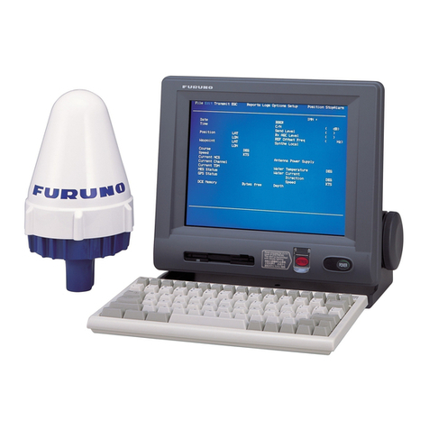
Furuno VR-5020 User manual

VDR DATA RECORDING UNIT VR-5020
Modification Procedure
(applicable to serial no. 5000 - 9999)
This technical information shows you how to modify the VR-5020.
Inner Capsule Modification Kit (Type: OP24-17-1, Code No. 000-038-228, for 6G
Type: OP24-46, Code No. 000-038-230, for 9G)
Necessary tools
No. Name Type Code No. Qty
1 Inner Capsule Assy. OP24-17-1-1 (for 6G) 001-065-820-00 1
OP24-17-2-1 (for 9G) 001-065-830-00
2 Repeater Board 24P0080(LF)-77 *HAND 001-119-590-00 1
3 Repeater Cover(1) 24-004-1243-2 100-347-102-10 1
4 Repeater Cover(2) 24-004-1244-2 100-347-112-10 1
5 Cover Fixing Washer 24-004-1245-1 100-347-121-10 1
6 Absorption Sheet 24-004-1228-1 100-333-621-10 1
7 Insulation Sheet 24-004-1232-1 100-333-641-10 1
8 Barrel Gasket 24-004-1214-4 100-312-574-10 1
9 Liner Sheet 24-004-1229-0 100-333-630-10 1
10 Protective Ring (jig) 24-004-1505-0 100-348-070-10 1
11 Fixing Plate 24-004-1246-0 100-348-050-10 1
12 Thermal Insulator Top 24-004-1247-0 100-348-060-10 1
13 Thermal Insulator(2) 24-004-1292-0 100-348-070-10 1
14 Reflective Tape 3150-A L2.5M 000-172-199-10 1
15 Pan Head Screw 3x10 SUS304 000-170-095-10 10
16 Washer Head Screw M4x10 C2700W MBNI2 000-163-167-10 2
17 Adhesive TB5211(SP) 50G 000-192-662-10 1
18 Silicone Grease KS-650N-100 (100 g) 000-166-579-10 1
19 Silicone Sealant KE-45-W-100 (100 g) 000-166-578-10 1
• Phillips Screwdriver • Plastic Head Hammer
• Slotted-head Screwdriver (total length less than 90 mm) • Box Cutter
• Hex Wrench (diagonal 5 mm) • Ethyl Alcohol
• Protective Mask, Protective Goggles, Rubber Gloves • Waste Cloths
• Cellophane tape • Torque wrench (10.0 Nm adjustable)
TOP
Projection Post
Nameplate
BOTTOM Data Recording Unit VR-5020
www.furuno.com
A
ll brand and product names are trademarks, registered trademarks or service marks of their respective holders.

2
1. How to disassemble the barrel housing cover
Remove the hinge pins from the
barrel fasteners to open the
fasteners.
Release the barrel fasteners.
Stand the DRU so the acoustic
beacon is DOWN.
Hinge pin
UP
Acoustic beacon
Set barrel housing
cover on a platform.
.
Blanket
Liner sheet
Stuffing
CAUTION
Use protective mask, protective goggles
and rubber gloves when handling.
Handling Stuffing/Blanket
Barrel fastener
Unfasten eight socket head
screws (with O-ring) with
hex wrench.
Mark alignment points on both bottom
and top sections with magic marker.
Remove the barrel housing by
hand. If unable, use the plastic
head hammer to tap the four
projections on the barrel housing
cover alternately to remove..
Note: The cable is not long
enough to be able to put the
barrel housing cover on the work
area. Set the cover on a platform
to prevent damage to the cable.
After removing the fixing plate,
remove the liner sheet
(transparent), blanket and
stuffing from the barrel housing.
Barrel cover
Fastener
Peel the reflective tape off the
top of the upper part of the
DRU. Make an alignment mark
as shown right.
Use the hex wrench (5mm
opposite side) to unfasten
the eight socket head screws.
Note:
1. Do not throw away the screw
plug and O-ring.
2. Be careful not to lose the
O-ring with the screw plug
3. Be careful that the O-ring
does not get dirty.
4. Use heat from a drier and a
scraper to neatly remove the
reflective tape.
Upper part reflective tape
Note:
1. Do not throw away the liner
sheet, stuffing and blanket.
2. Replace the capsule if the
stuffing or blanket is wet.
3. Be sure to completely
remove the stuffing and
blanket .

3
2-1. How to remove the repeater box from the barrel housing cover
2-2. How to remove the repeater box from the barrel cover
Black type: 6G serial number 7127 or greater, 9G serial number 7366 or greater)
Unfasten four screws (M3) from
the repeater box.
Unfasten two screws (M4) from
the cable fixing plate. Disconnect
the cable. Remove the repeater
box from the barrel cover.
(Discard the repeater box.)
Repeater box
Note: Mark the direction of cable entry
inside the barrel cover.
Repeater cover
Insert minus driver into
the groove shown
Remove the six screws (M3) from the
repeater box, and remove the cover.
Note: Mark the direction of cable entry
inside the barrel cover.

4
3. How to replace the barrel gasket (6G: serial number 6898 or earlier, 9G: serial number
or earlier)
Remove board screws (M3,
4 pcs.) from the repeater box,
and remove the repeater
board. (Dispose of the Repeat-
er board)
Remove the 2 screws for the
cover mounting washer (M4)
Note: Discard cover mounting
washer
Remove the repeater box
(base).
Note: Discard the repeater box
(base).
Remove the barrel gasket. Wipe
the gasket junction on the barrel
housing cover with ethyl alcohol.
Coat all around the junction and
the barrel gasket with silicone
grease (KS-650N-100).
Insert the barrel gasket.
Current barrel gasket (view from "A")
New barrel gasket (view from "A")
A
How barrel gasket is inserted
Barrel gasket
Note:
1. If the barrel gasket is old be
sure to replace with new barrel
gasket (24-004-1214-4).
2. If very dirty, carefully clean
the inlay area with an alcohol
cleaner.
Barrel gasket

5
4. How to disassemble the data recorder
Remove the thermal insulator(2).
Handle the thermal insulator with
care; it breaks easily. If the
insulator is damaged, see page
10 for how to judge if it is usable.
Use the box cutter to cut away
the film. Remove only the upper
part of the thermal insulator(1).
Thermal insulator(2)
Notes on handling the thermal insulators
- Do not wet the insulators.
- Use protective mask, protective
goggles and rubber gloves to handle.
Approx 1 cm
U
se box cutter to cut
away top part of
thermal insulator (1).
Pull out inner capsule
(enclosed in plaster).
Use the box cutter to cut away
the top part of the thermal
insulator(1). Pull out the inner
capsule (enclosed in plaster.)
Thermal insulator(1)
Inner capsule
Note:
1. Do not get the insulator wet.
Water will cause the insulator
to shrink.
2. Align the cable exit position
to the marking on the unit.
Note:
1. Two people are required for
removing the inner capsule.
2. Lift vertically when removing
the insulator. If you twist while
lifting, there is a possibility of
damaging the insulation.
3.Pull out the inner capsule in
one shot to avoid damaging the
insulation.
4. Pull on the silicone at the
cable entrance to pull out the
cable.
5. If it is difficult to remove, turn
the barrel housing (capsule)
upsidedown and remove
through the plaster pot. Howev-
er, be careful that excess insual-
tion does not fall out.
Note:
1. Be sure to cut the film so that
it does not wrap to the inner
capsule when inserting.
2. If the insulator is scratched or
detached, reform it.
3. Dispose of the top of insula-
tor (1).
There is no problem
even if the insulator
has been removed with
the inner capsule.

6
5. How to assemble the data recorder
Insert the thermal insulator top,
noting the direction.
Set the protective ring
(24-004-1505-0)
Tie the rope with a bowknot,
being careful not to damage the
thermal insulator, set the inner
capsule in the barrel housing
using the piece of rope.
After inserting the inner capsule,
untie the rope and fasten it with
cellophane tape.
BOTTOM
Notch
Screw hole
Center
(visible)
Screw hole
TOP
*
*
Positional relation
between notch and
screw holes
Thermal
insulator
top
Projection
TOP
BOTTOM
Post
One post: TOP
Two posts: BOTTOM
Align cut part in protective ring with notch
in thermal insulator top.
Barrel housing direction
As shown below, position notch
in thermal insulator top so that it
is at center of top right two screw
holes (* in figure) on barrel
housing.
Note: Align the notch of
the insulator as shown
right.
Note: Open the cut part in
the protective ring and set
it.

7
Remove the protective ring.
Set the stuffing in the cable
entry groove.
Adhere the thermal insulator(2)
with adhesive (TB5211(SP)
50G).
Fasten the fixing plate
(24-004-1246-0).
Set stuffing in groove.
Fixing plate
Fasten fixing plate
next to cable exit.
Thermal
insulator(2)
Adhesive
Protective ring
Note:
1. Be carefel that cable does
not pinch.
2. Be careful of the position of
the cable and the fixing plate.
The cable extends from the
right side of the fixing plate
position.

8
6. How to assemble the repeater box
Wipe the barrel housing cover
with ethyl alcohol.
Coat the repeater cover(1)
(24-004-1243-2) with adhesive
(TB5211(SP) 50G).
How to position the barrel
housing cover and repeater
cover(1).
Set the absorption sheet
(24-004-1232-1) on the repeater
cover(1) and place the insula-
tion sheet (transparent) on it.
Coat the groove in the repeater
cover(1) with adhesive
(TB5211(SP) 50G).
TOP
BOTTOM
Fasten repeater cover(1) so
its cable exit is bottom side.
Projection
TOP
BOTTOM
Cover fixing
washer
TORQUE:
1.47 NQm
Insulation
sheet
2 mm
Absorption
sheet
One post: TOP
Two posts: BOTTOM
Coat groove
with adhesive.
Barrel housing direction
Post
Fill within
2 mm from
groove bottom
5 to 8 mm
Amount of adhesive
Coat the two washer head
screws (M4x10) with adhesive
(TB5211(SP) 50G). Set the
cover fixing washer to the hole
of the repeater cover and fasten
the cover fixing washer with the
washer head screws.
Note: Align the cable insertion
entrance with the mark inside
the barrel cover.
Coat all around
edges with adhesive
2-3 mm in width.
2 mm
Remove excess adhesive
from the hole.

9
Coat all around
with adhesive
(5 mm width)
TORQUE:
0.59 NQm
TORQUE:
0.59 NQm
Set the Repeater board to the
four posts on the repeater
cover (1). Fasten the board
with four pan head screws
(3×10).
Apply a thin coat of adhesive
(TB5211(SP) 50G) to the
projection on the repeater
cover(2) (24-004-1244-2)
Mate the repeater cover(2) to
the repeater cover(1).
Fasten the repeater cover(2)
together with six pan head
screws (3×10). Wipe off excess
adhesive.
5-8 mm
Amount of adhesive
2 mm㻌
Lightly coat projection
with adhesive.
Plug the connector from the
inner capsule into the Repeater
board. Coat the neck of the
connector with adhesive
(TB5211(SP) 50G).

10
Put the stuffing
around the repeater
cover.
Set the stuffing so
the repeater cover is
visible.
Put the blanket on
the stuffing so that its
edge is below the
difference in level in
the barrel housing
cover.
Put the liner sheet on
the blanket so that its
edge is below the
difference in level in
the barrel housing
cover.
Clean around the
edge of the barrel to
remove foreign
material. Coat
junction of barrel
housing with silicone
grease.
Use the hex wrench
(5mm opposite side)
to fix the barrel
housing cover with
eight screw plugs.
How to fasten screw plugs
1. Loosely fasten plugs.
2. Tighten in order shown below.
TORQUE:
10.0
NQm
3. Check and tighten in order shown
below.
Wipe barrel housing cover junction before fastening cover
Blanket
Liner sheet
Cable details
Put stuffing so that
repeater cover is
visible.
BOTTOM
Use protective mask, protective goggles
and rubber gloves when handling.
Handling Stuffing/Blanket
Barrel housing direction
Projection
TOP
BOTTOM
One post: TOP
Two posts: BOTTOM
Post
CAUTION
How to mount barrel housing cover
While pulling the cable, turn barrel housing cover to
set cover to barrel housing, Confirm that alignment
points meet.
Coat threads with
silicone grease.
Clean hole thoroughly then put silicone grease in
hole. Push down barrel housing cover and
tighten screw plugs.
Confirm o-ring
Screw plugs
(8 pcs.)
Barrel housing cover assy.
Coat junction of barrel housing
with silicone grease.
Barrel housing cover assy.
Note:
1. Re-use the blanket
and stuffing.
2. Insert stuffing
under the repeater
box.
3. Securely press
down the liner sheet.
Note:
1. Do not pinch the
cable, when the
barrel cover is
attached properly the
cable is not pinched.
2. Confirm the cable
position is aligned to
the marking and affix
the barrel cover.
3. Confirm the
O-rings of the screw
plugs are in place.
4. Confirm the torque
of the screw plugs
and fastening order.
As shown above, position cable
so that it comes out from
bottom of repeater cover at the
45-degree position (clockwise).

11
How to judge the suitability of the thermal insulation (2)
Wipe the barrel
housing with ethyl
alcohol. Attach the
reflective tape as
shown in the
illustration.
Fasten the DRU to its
mounting bracket as
shown in the illustra-
tion.
TOP
BOTTOM
Center (visible)
Barrel housing
DATA RECORDER UNIT
Position so
characters
can be read.
Insert
Mounting
bracket
VIEW
How to fasten DRU to
mounting bracket
1
Fasten DRU to mounting bracket
Reflective tape
Hinge pin
(2 pcs.)
Mount so the flat part touches
the barrel housing.
Mounting bracket
Refer to the VR-3000/3000S Installation Manual to connect the IEEE1394 cable from the DCU. After
connecting the cable, apply the included silicone sealant (KE-45-W-100) to the connection point.
Note: Affix reflective
tape included in the
kit.
Chain
The insulation can be used if its condition is
similar to those shown in the photographs.

12
Check Sheet
1. Barrel housing (capsule) cover removal
1. Make alignment markings before removing • 1 on cover and main body
2. Do not lose the O-ring of the screw plug and confirm
that there is no dust
•M8x8
3. Deposit the stuffing and blanket into a plastic bag for
re-use
•
4. Confirm that barrel and blanket is not wet or damp • If no good, change capsule
2-1. Repeater box removal
1. There is a black type and stainless type repeater
box, confirm which type you have
•
2. Make a mark to indicate the direction of the repeater
cable insertion inside the barrel cover
•
2-2. Repeater box (black type) removal
1. Make a mark to indicate the direction of the repeater
cable insertion inside the barrel cover
•
3. Replacement of Barrel Gasket
1. Replace old gasket with new gasket •
4. Disassembly of data recording unit
1. Ensure insulator is not wet. •
2. Make a mark to indicate the direction of the repeater
cable insertion inside the barrel cover
•
3. Ensure inner capsule is pulled out vertically. • Do not rotate
4. Cut and remove the film •
5.Reform the insulator (1) for cracks or defects •
5. Assembly of data recording unit
1. Align the position of the gap on the top of the insula-
tor and the position of 4-2.
•
2. Insert the inner capsule after setting the insulator
protection ring.
•
3. Fill the gap in the cable with bulk •
4. Confirm the cable is not pinched after attaching insu-
lator (2).
•
5. Confirm fixing plate and cable position • Cable must protrude from the side of
the fixing plate
6. Repeater box assembly
1. Remove old silicone sealant • Cable exit
2. Apply adhesive • Repeater cover (1) neck
• Repeater cover (2) projection
• Panhead screw A (2 screws)
• Connector base
3. Install absorption sheet • 1 sheet
4. Place stuffing under repeater box •
5. Confirm fixing plate and cable position • Cable must protrude from the side of
the fixing plate.
6. Dispose of garbage from barrel cover and barrel
backing
•
7. Apply grease to repeater over and gasket •
8. Confirm cable is not pinched when installing •
9. Apply grease to O-ring of the screw plug • 8 Screw plugs

13
10. Confirm screw plug is fastened correctly • Fasten loosely, then tighten finally.
11. Manage screw plug torque pressure • Torque pressure: 10.0N m, M8 x 8
12. Change reflective tape •

This page is intentionally left blank.

14
⑤押え板とケーブル位置確認。 □押え板横からケーブルがでること。
⑥バレルパッキンとバレルカバーに付着しているゴミを除去。 □
⑦カバーとパッキンにグリース塗布。 □
⑧嵌合時にケーブルが噛んでいないか。 □
⑨スクリュープラグの Oリングにグリス塗布。 □8箇所
⑩スクリュープラグの締め方確認。 □本締め
確認締め
⑪スクリュープラグの締付けトルク管理。 □締付けトルク:10.0N・m
M8×8箇所
⑫反射シールの貼り替え。 □

13
1. バレルハウジング(カプセル)のカバー取り外し
①取り外す前に位置合わせマーキング。 □本体とカバー各 1箇所。
②スクリュープラグの Oリング紛失、ゴミ付着注意。 □M8×8個
③バルク、ブランケットは再利用するのでビニール等に入れて保
管する。
□
④バルク、ブランケットが濡れていないか、湿っていないか確認。 □不良の場合はカプセル交換。
2-1. リピータボックスの取り外し
①リピータボックスに黒色タイプとステンレスタイプがあるので
確認。
□
②ケーブル挿入口の方向をバレルカバー内側に記載すること。
2-2. リピータボックス(黒色タイプ) の取り外し
①ケーブル挿入口の方向をバレルカバー内側に記載すること。 □
3. バレルパッキンの交換
①旧パッキンは新パッキンに交換。 □
4. データ記録器の分解
①WDS 断熱材は水にぬらさない。 □
②ケーブル出口は位置マーキングをカプセル本体側にする。 □
③インナーカプセルを垂直に引き上げる。(回転させて引き上げな
い)
□
④フィルムを切り取る。 □
⑤WDS 断熱材の傷、ヒビ、欠損は整形する。 □
5.データ記録器の組立
①WDS 断熱材トップの溝位置と 4-2 の位置を合わせる。 □
②WDS 保護リングを載せてからインナーカプセルを挿入する。 □
③ケーブル溝部にはバルクで隙間を埋める。 □
④WDS 断熱材(2)を取り付け後ケーブルが噛んでいないか。 □
⑤押え板とケーブル位置を確認。 □押え板横からケーブルが出ること。
6.リピータボックスの組立
①古いシリコンゴムははがす。 □ ケーブル出口
②接着剤の塗布。 □リピータカバー(1) 溝部
リピータカバー(2) 凸部
ナベセムス Aネジ 2個
コネクタ根元
③吸湿シートの取り付け。 □1枚
④バルクをリピータ下部に詰め込む。 □

12
脱脂後、DRU 上側の反射シートを貼
り付ける。
注) キット内の反射シートを貼ること。
DRU を元のように防振台に取り付け
る。
VR-3000/3000S の装備要領書を参照して、DCU からの IEEE1394 ケーブルを接続する。キットの中のシリコ
ンゴム KE-45-W-100 は、ケーブルを接続したあと接続箇所に塗布する。
WDS 断熱材(2) の使用可否限度
反射シート
3150-A 2.5m
写真の破損程度までなら使用可能
(これ以上破損した場合は、新品を調達して交
換する)

11
リピータカバーが見えるようにバルク
をバレルカバーに詰める。
バルクの上にブランケットを載せ、外
周部をバレルカバーの段差の下に潜
りこませる。
その上に隔壁シートを載せ、外周部を
バレルカバーの段差の下に潜りこま
せる。
注)
① ブランケットとバルクは再利用。
② リピータボックスの下部にもバル
クを押し込むこと。
③ 隔壁シートでしっかり押さえ込む
こと。
バレルカバーの嵌合部のゴミ等を除
去し、バレルハウジングの嵌合部にオ
イルコンパウンド(シリコングリス)を塗
る。
バレルカバーを嵌合させて六角レンチ
(対辺5mm)でスクリュープラグ(8
個)を締め付ける。
注)
① ケーブルが噛まないこと。ケーブ
ルの長さは噛まないようになって
いる。位置合わせマーキング(2
ページ)が合うようにバレルカバ
ーを押し込む感覚で嵌合するこ
と。
② スクリュープラグの O リングがあ
ることを確認。
③ スクリュープラグにグリスを塗布。
④ スクリュープラグの締め付けトル
クと本締め・確認締めの順序に注
意。
ブランケット
隔壁シート
ケーブルについて
ケーブルはバレルカバーの地側から
右回り(時計回り)に 45°の位置より
出す
バレルハウジングの方向
突起
天側
地側
支柱 1本の側が天側、2本の側が地側
支柱
リピータカバーが見える
ようにバルクを詰める
参考
締付
トルク
10.0 N
・
m
地側
バレルカバー組立前に嵌合部のゴミ等を除去する
深座グリ座面を清掃し、シリコングリスを塗布。
挿入状態では、バレルカバーが少し浮いた状態になるので
、
上からバレルカバーを押し付けネジ止めする。
バレルハウジングの嵌合部
シリコングリスを塗る
バレルカバーの取付け
ケーブルをたるませず張った状態でバレル内に納めバレル
カバーを回しながら嵌合させていく。
挿入後は、バレルカバー/バレルハウジングの向き(天地)
が合っていることを確認する。
3)下図の順で確認締め
スクリュープラグの締付け順
1)8 本を仮止めする
2)下図の順で本締め
スクリュープラグのネジ部にシリコングリス
を
塗布
O リングが有ることを確認
バレルカバー
スクリュープラグ
注意!
作業時は防塵マスク、防塵メガネ
、
天然ゴム手袋を使用すること。

10
インナーカプセルから出ているケーブ
ルのコネクタをリピータ基板に差し込
み、コネクタ根元に接着剤
(TB5211(SP) 50G)を塗布する。
リピータカバー(1)のボス4箇所とリピ
ータ基板の位置を合わせ、+ナベPタ
イトザツキ(3x10、4個)で取り付け
る。
リピータカバー(2)(24-004-1244-2)
の凸部に薄く接 着 剤 ( TB5211(SP)
50G)を塗布したあと、リピータカバー
(2)をリピータカバー(1)にかぶせる。
+ナベPタイトザツキ(3x10、6個)で
リピータカバー(2)を取り付ける。
(はみ出た接着剤はふき取る)
接着剤
全周5mm
参考
締付トルク 0.59N・m
参考
締付トルク 0.59N・m
5~8mm
接着剤盛り
接着剤を塗布
2mm
凸部に薄く接着剤を塗布

9
6.リピータボックスの組立
バレルカバーはエチルアルコール
で脱脂し、リピータカバー(1)
(24-004-1243-2)に接着剤
(TB5211(SP) 50G)を塗る。
注)シリコンゴムをきれいにはがし
てから再塗布のこと。
バレルカバーとリピータカバー(1)の
位置を合わせて置く。
カバー取付座金をリピータカバー(1)
の穴に置き、ナベセムスAネジ(M4x
10、2個)に接 着 剤 ( TB5211(SP)
50G)を塗布して取り付ける。
注)ケーブル挿入口とマークの方向を
合わせる(3、4 ページで付けたマー
ク)。
リピータカバー(1)の上に吸湿シート
(24-004-1232-1)を置き、その上に絶
縁シート(透明)を置く。
リピータカバー(1)の溝部に接着剤
(TB5211(SP) 50G)を塗布する。
天側
地側
リピータカバーのケーブルの
出口が地側になるように取り
付ける
バレルハウジング方向表示図
突起
天側
地側
支柱 1本の側が天側、2本の側が地側
支柱
カバー取付座金
参考
締付トルク 1.47N・m
接着剤をカド部
全周に 2~
3mm 塗布
絶縁シート
吸湿シート
5~8mm
接着剤盛り
接着剤を塗布
2mm
溝面から
2mm 以下
溝に接着剤を
塗布
穴部にはみ出した接着剤は
除去のこと
Table of contents
Other Furuno Marine Equipment manuals

Furuno
Furuno DS-50 User manual

Furuno
Furuno TZTBB User manual

Furuno
Furuno FA-30 User manual

Furuno
Furuno DS-85 User manual

Furuno
Furuno DSC-6 User manual

Furuno
Furuno TECDIS User manual

Furuno
Furuno MFDBB User manual
Furuno
Furuno NavPilot 711 User manual

Furuno
Furuno TZT-3KP-F3D User manual

Furuno
Furuno FI70BW Instruction Manual

Furuno
Furuno NavNet TZtouch3 Series User manual

Furuno
Furuno FI-70 User manual

Furuno
Furuno FE-800 User manual

Furuno
Furuno FE-880T User manual

Furuno
Furuno GP-39 User manual

Furuno
Furuno FCV-600L User manual

Furuno
Furuno GP-1810F User manual

Furuno
Furuno TZT9 User manual

Furuno
Furuno DSC-6 Manual

Furuno
Furuno FMD-3200 User manual