GAI-Tronics 234WM-202 User manual

Pub. 42004-308G
GAI-TRONICS 3030 KUTZTOWN RD. READING, PA 19605 USA
610-777-1374 800-492-1212 Fax: 610-796-5954
VISIT WWW.GAI-TRONICS.COM FOR PRODUCT LITERATURE AND MANUALS
GAI-TRONICS®
AHUBBELL COMPANY
Model 234WM-202
Wall-Mount Stanchion Assembly
Confidentiality Notice
This manual is provided solely as an installation, operation, and maintenance guide, which contains
sensitive business and technical information that is confidential and proprietary to GAI-Tronics. GAI-
Tronics retains all intellectual property and other rights in or to the information contained herein, and
such information may only be used in connection with the operation of your GAI-Tronics product or
system. This manual may not be disclosed in any form; in whole or in part, directly or indirectly, to any
third party.
General Information
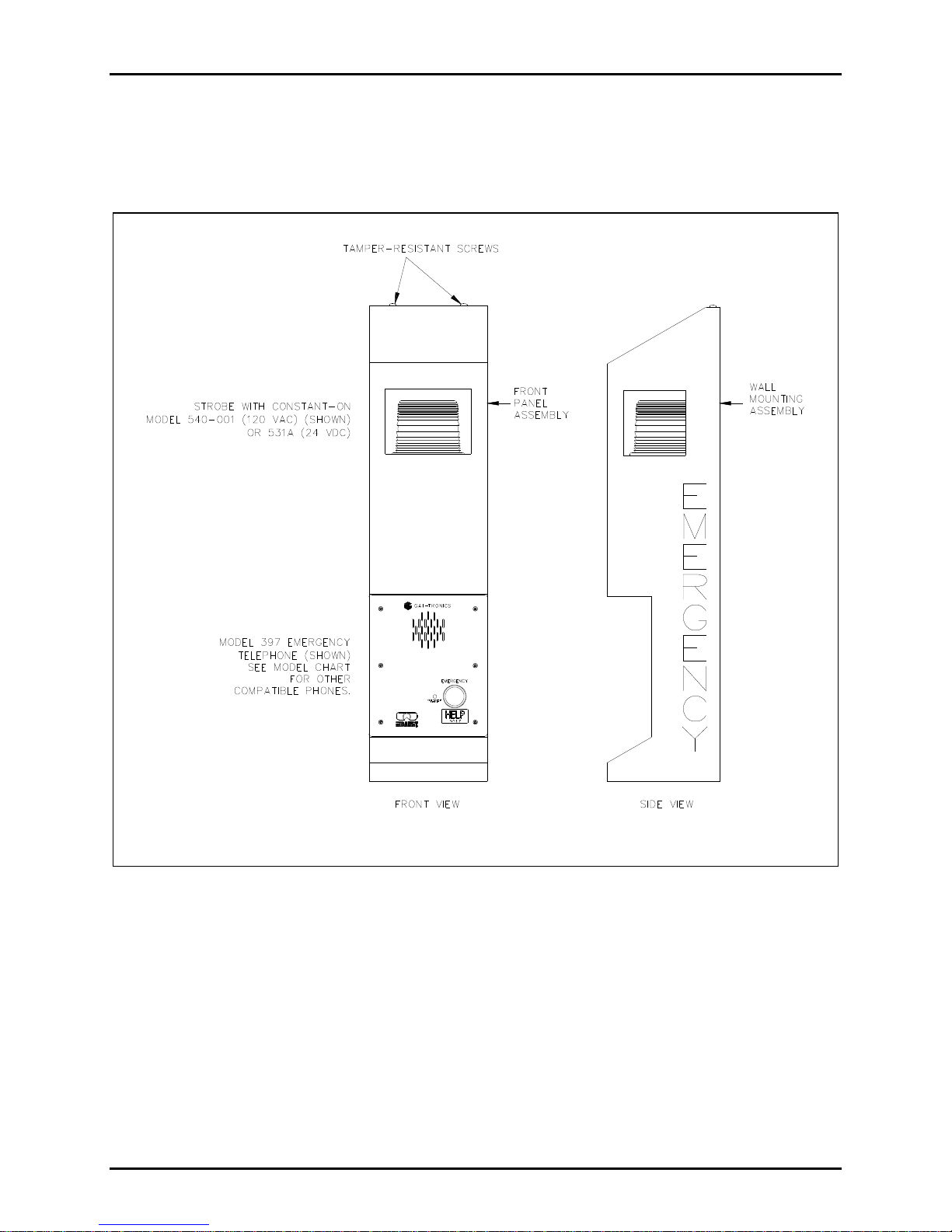
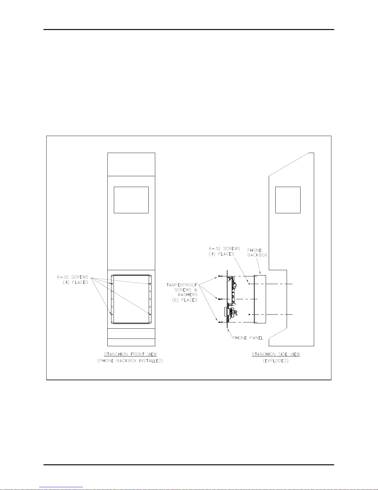
The Model 234WM-202 Wall-Mount Stanchion Assembly is part of a completely integrated emergency
communications station and is designed to house a GAI-Tronics Model 39xor 27xSeries Flush-Mount
Telephone and a Model 540-001or 531A Strobe (each sold separately). The stanchion is a simple,
attractive, yet highly visible unit measuring 40.5 inches (1.03 meters) tall.
GAI-Tronics enhanced emergency telephones are designed for isolated high-risk areas requiring
emergency communications equipment. Emergency telephone users simply press the clearly labeled
emergency push button for immediate connection to a user-programmed central security telephone
number.
The strobe creates added visibility to emergency telephone locations by providing a constant-on lamp that
automatically flashes when the emergency button is pressed. The telephone is also highly visible; a light
mounted in the stanchion shines on the front of the telephone to illuminate the telephone for nighttime
use.
The Model 234WM-202 Wall-Mount Stanchion Assembly consists of the Model 84505-202 Wall-Mount
Stanchion and the Model 84503-30xPanel Light Assembly (each packaged separately). The strobe and
the emergency telephone are purchased and packaged separately.

Pub. 42004-308G
Model 234WM-202 Wall-Mount Stanchion Assembly Page 2 of 11
p:\standard ioms - current release\42004 instr. manuals\42004-308g.docx
04/16
Installation
The following sections provide information on the installation of the complete wall-mount stanchion.
Figure 1. Model 234WM-202 Wall-Mount Stanchion Assembly

Pub. 42004-308G
Model 234WM-202 Wall-Mount Stanchion Assembly Page 3 of 11
p:\standard ioms - current release\42004 instr. manuals\42004-308g.docx
04/16
Model 84505-202 Wall-Mount Stanchion Installation
1. Remove and save the two tamper-resistant screws at the top of the stanchion. See Figure 1.
NOTE:GAI-Tronics Model 233-001 Security Screwdriver (sold separately) is required to remove the
tamper-resistant screws.
2. Remove the wall-mounting assembly from the front panel assembly. Refer to Figure 1. Detach the
chain from the wall-mounting assembly. See Figure 2.
3. Enlarge the conduit entry pilot hole(s) to be used for the stanchion power cables. See Figure 3.
4. Fasten the wall-mounting assembly to a wall or flat surface that can support at least 50 pounds, using
3/8-inch bolts. Refer to Figure 2 for mounting hole dimensions and ADA height requirements.
Figure 2. Wall Mounting Instructions

Pub. 42004-308G
Model 234WM-202 Wall-Mount Stanchion Assembly Page 4 of 11
p:\standard ioms - current release\42004 instr. manuals\42004-308g.docx
04/16
Grounding Requirements
This unit must be grounded in accordance with the National Electrical Code (NEC) in the United States or
the Canadian Electrical Code (CEC) in Canada. A #10 grounding stud has been provided at the base of
the stanchion for grounding. Connect the #10 grounding stud to a grounding electrode. A grounding
electrode rod is typically 8 feet (2.44 m) long per NEC 250, or 9.84 feet (3 m) long per CEC Rule 10.
Figure 3. Conduit/Surge Protection Locations

Pub. 42004-308G
Model 234WM-202 Wall-Mount Stanchion Assembly Page 5 of 11
p:\standard ioms - current release\42004 instr. manuals\42004-308g.docx
04/16
Tempered Glass Installation (Factory Installed)
1. Remove the keps nuts, spacer brackets, and holding brackets. These parts will be used for holding the
glass in place.
2. Carefully unpack the glass from the box located in the telephone mounting area of the Model
234WM-202 Wall-Mount Stanchion.
3. Center the front glass left to right and top to bottom around the opening in the front panel assembly
and fasten in place using the spacer brackets, holding brackets, and keps nuts removed previously.
Refer to Figure 4 for assembly details.
NOTE:Do not exceed 24 inch-pounds of torque on the keps nuts.
4. Repeat the above steps for both side glass pieces.
Figure 4. Glass Installation Instructions

Pub. 42004-308G
Model 234WM-202 Wall-Mount Stanchion Assembly Page 6 of 11
p:\standard ioms - current release\42004 instr. manuals\42004-308g.docx
04/16
Model 84503-30x Stanchion Panel Light Installation
1. Align the stanchion panel light assembly inside the stanchion as shown in Figure 5.
2. Model 84503-301: Extend the black (hot), the white (neutral) and the green (ground) wires to the
base of the stanchion (these wires will be connected later, along with the strobe wires, to the incoming
power wires in accordance with the electrical codes).
Model 84503-302: Extend the black (−) and the white (+) wires to the base of the stanchion (these
wires will be connected later, along with the strobe wires, to the incoming power wires in accordance
with the electrical codes).
3. Secure the panel light assembly with the two mounting screws provided. Apply a small amount of
clear RTV silicone sealant or equivalent to each screw thread to reduce the possibility of rust forming
in the screw threads.
Figure 5. Stanchion Panel Light Assembly

Pub. 42004-308G
Model 234WM-202 Wall-Mount Stanchion Assembly Page 7 of 11
p:\standard ioms - current release\42004 instr. manuals\42004-308g.docx
04/16
Model 540-001 or Model 531A Strobe Installation
1. Insert the strobe’s seven 15-foot wires through the stanchion’s threaded nipple, and allow the wires to
extend to the bottom of the stanchion. See Figure 6.
2. Screw the strobe onto the threaded nipple.
3. Separate the orange and violet wires necessary for the telephone connection and extend those wires
through the stanchion cutout for the telephone.
Figure 6. Strobe Assembly

Pub. 42004-308G
Model 234WM-202 Wall-Mount Stanchion Assembly Page 8 of 11
p:\standard ioms - current release\42004 instr. manuals\42004-308g.docx
04/16
Emergency Telephone Installation
1. Separate the back box from the front panel of the telephone. The parts envelope inside the back box
contains eight #6-32 self-tapping flat head screws, six tamperproof screws, six washers, and a hole
plug.
2. Place the back box into the telephone opening from the front of the stanchion. Mount the box using
four of the #6-32 self-tapping flat head screws. Refer to Figure 7 below. The telephone back box has
two openings, one in the top and one in the bottom. Plug the top opening with the hole plug. The
bottom of the back box is the recommended entry location for the telephone line and strobe control
wires.
Figure 7. Telephone and Back Box Installation
3. Install a telephone line surge suppressor (sold separately) on the protection bracket on the bottom of
the stanchion wall-mounting assembly. See Figure 3.
4. Install a ground wire between the telephone line surge suppressor (sold separately) and the grounding
lug on the bottom of the stanchion. See Figure 8
5. Connect the telephone line to the surge protection as shown in Figure 8.

Pub. 42004-308G
Model 234WM-202 Wall-Mount Stanchion Assembly Page 9 of 11
p:\standard ioms - current release\42004 instr. manuals\42004-308g.docx
04/16
6. Connect the telephone cable from the surge protection, and feed the cable through the bottom access
hole of the telephone back box and allow it to hang free.
7. Bring the orange and violet strobe unit wires through the bottom access hole of the back box, and
allow them to hang free.
8. The telephone front panel is shipped from the factory with a cable and modular plug attached to TB1.
If desired, an optional modular telephone jack can be mounted to the inside of the back box allowing
the use of the cable and modular plug that is attached to TB1. If the telephone line is to be hard-wired
to the telephone, this cable can be removed and discarded.
9. Attach the telephone cable from the surge protector to TB1 on the telephone PCBA as shown in
Figure 8.
10. Attach the strobe’s violet and orange control wires to TB2 on the telephone PCBA as shown in
Figure 8.
11. Install the telephone’s front panel using the six tamper-resistant screws and six washers provided.
NOTE:Excessive tightening will cause the panel to warp. Do not over-tighten.
Wiring Power Connection
All wiring connections should be complete at this point, with the exception of the stanchion panel light
and strobe wire connections to the incoming power lines. All connections must be made in accordance
with the National Electrical Code (NEC) in the United States or the Canadian Electrical Code (CEC) in
Canada. Install the power lines per Figure 8 for ac installations or Figure 9 for dc installations.
Figure 8. Interconnection Diagram with AC-Powered Strobe

Pub. 42004-308G
Model 234WM-202 Wall-Mount Stanchion Assembly Page 10 of 11
p:\standard ioms - current release\42004 instr. manuals\42004-308g.docx
04/16
Figure 9. Interconnection Diagram with DC-Powered Strobe
Repairing Surface Damage to Powder-Coated Stanchions
1. Carefully sand the damaged area to clean and score the base metal, taking care to minimize any
additional damage to the surrounding powder coating.
2. Wipe the sanded area with a cleaning solvent, such as DuPont “PrepSol” or equivalent. Allow the
area to dry. This type of product is normally available at auto parts stores. Denatured alcohol may
also be used.
3. Prepare the bare metal surface for painting by treating it with a phosphoric acid solution intended for
this purpose. The phosphoric acid solution is also normally available at auto parts stores. Allow the
area to dry.
4. Using a cotton-tipped swab or small brush, paint the prepared surface with an automotive enamel or
oil base polyurethane enamel such as Red Devil, Rustoleum, or equivalent. Do NOT use Krylon-type
paints. Carefully blend the repair enamel into the powder coat at the edges.
NOTE:Exact color matches may not be attainable.

Pub. 42004-308G
Model 234WM-202 Wall-Mount Stanchion Assembly Page 11 of 11
p:\standard ioms - current release\42004 instr. manuals\42004-308g.docx
04/16
Specifications
Dimensions .................................................................... 40.5 H × 10.0 W × 9.5 D in (0.25 0.24 1.03 m)
Wall thickness.................................................................................................................................... 0.125 in
Wall material..................................................................................................................................Aluminum
Finish ................................................................................................................ Textured powder-coat epoxy
Power ratings:
Model 540-001 AC Strobe ........................................................................................ 0.39 A @ 120 V ac
Model 531A DC Strobe................................................................................................. 2.7 A @ 24 V dc
Model 84503-301 AC Panel Light Assembly ................................................... 25 mA @ 120–230 V ac
Model 84503-302 DC Panel Light Assembly ........................................................ 40 mA @10–33 V dc
Weight............................................................................................................................Approximately 40 lb
Approvals
UL/cUL listed telephone stanchion................................Canadian Electrical Code, Part I (CE Code, Part I),
and the ANSI/NFPA 70 National Electrical Code (NEC)

(Rev. 10/06)
Warranty
Equipment. GAI-Tronics warrants for a period of one (1) year from the date of shipment, that any
GAI-Tronics equipment supplied hereunder shall be free of defects in material and workmanship, shall
comply with the then-current product specifications and product literature, and if applicable, shall be fit
for the purpose specified in the agreed-upon quotation or proposal document. If (a) Seller’s goods prove
to be defective in workmanship and/or material under normal and proper usage, or unfit for the purpose
specified and agreed upon, and (b) Buyer’s claim is made within the warranty period set forth above,
Buyer may return such goods to GAI-Tronics’ nearest depot repair facility, freight prepaid, at which time
they will be repaired or replaced, at Seller’s option, without charge to Buyer. Repair or replacement shall
be Buyer’s sole and exclusive remedy. The warranty period on any repaired or replacement equipment
shall be the greater of the ninety (90) day repair warranty or one (1) year from the date the original
equipment was shipped. In no event shall GAI-Tronics warranty obligations with respect to equipment
exceed 100% of the total cost of the equipment supplied hereunder. Buyer may also be entitled to the
manufacturer’s warranty on any third-party goods supplied by GAI-Tronics hereunder. The applicability
of any such third-party warranty will be determined by GAI-Tronics.
Services. Any services GAI-Tronics provides hereunder, whether directly or through subcontractors,
shall be performed in accordance with the standard of care with which such services are normally
provided in the industry. If the services fail to meet the applicable industry standard, GAI-Tronics will
re-perform such services at no cost to buyer to correct said deficiency to Company's satisfaction provided
any and all issues are identified prior to the demobilization of the Contractor’s personnel from the work
site. Re-performance of services shall be Buyer’s sole and exclusive remedy, and in no event shall GAI-
Tronics warranty obligations with respect to services exceed 100% of the total cost of the services
provided hereunder.
Warranty Periods. Every claim by Buyer alleging a defect in the goods and/or services provided
hereunder shall be deemed waived unless such claim is made in writing within the applicable warranty
periods as set forth above. Provided, however, that if the defect complained of is latent and not
discoverable within the above warranty periods, every claim arising on account of such latent defect shall
be deemed waived unless it is made in writing within a reasonable time after such latent defect is or
should have been discovered by Buyer.
Limitations / Exclusions. The warranties herein shall not apply to, and GAI-Tronics shall not be
responsible for, any damage to the goods or failure of the services supplied hereunder, to the extent
caused by Buyer’s neglect, failure to follow operational and maintenance procedures provided with the
equipment, or the use of technicians not specifically authorized by GAI-Tronics to maintain or service the
equipment. THE WARRANTIES AND REMEDIES CONTAINED HEREIN ARE IN LIEU OF AND
EXCLUDE ALL OTHER WARRANTIES AND REMEDIES, WHETHER EXPRESS OR IMPLIED BY
OPERATION OF LAW OR OTHERWISE, INCLUDING ANY WARRANTIES OF
MERCHANTABILITY OR FITNESS FOR A PARTICULAR PURPOSE.
Return Policy
If the equipment requires service, contact your Regional Service Center for a return authorization number
(RA#). Equipment should be shipped prepaid to GAI-Tronics with a return authorization number and a
purchase order number. If the equipment is under warranty, repairs or a replacement will be made in
accordance with the warranty policy set forth above. Please include a written explanation of all defects to
assist our technicians in their troubleshooting efforts.
Call 800-492-1212 (inside the USA) or 610-777-1374 (outside the USA) for help identifying the
Regional Service Center closest to you.
Table of contents
Other GAI-Tronics Emergency Phone manuals

GAI-Tronics
GAI-Tronics PHP400 User manual

GAI-Tronics
GAI-Tronics 293-103 User manual

GAI-Tronics
GAI-Tronics RED ALERT User manual

GAI-Tronics
GAI-Tronics Redalert 392-001 User manual

GAI-Tronics
GAI-Tronics Red Alert 300 Series User manual

GAI-Tronics
GAI-Tronics Help Point PHP400 GSM User manual

GAI-Tronics
GAI-Tronics PHP400 User manual