Ganz DR-16F44-AT User manual

1

2
CONTENT
OVERVIEW
3 Safety Instruction
4 Caution
4 Key Features
5What’s included?
6 Front Panel
7 Rear Panel
8 Remote Control At a Glance
INSTALLATION
10 HDD Installation/Replacement
12 Basic Layout
13 Connecting to an external devices

3
OVERVIEW
Safety Instruction
This product was tested with a UPS to satisfy EN 61000-4-11 test conditions (voltage dips and short
interruptions test) under the EN 50130-4: 2011 standard. For your safety, we provide a few
instructions about installation, manipulation, cleaning, assembly/disassembly of the product as
below. So please read carefully and comply with the instructions.
Before installation
Comply with the following instructions to prevent a fire, explosion, system failure or electric shock.
Remove the power supply module before proceeding.
Check the input voltage (AC100V–AC240V) to the power supply module before connecting it.
Keep the product away from humidity.
Ensure that all devices connected to the product should be properly earth-grounded.
In operation mode
Comply with the following instructions to prevent a fire, explosion, system failure or electric shock.
If you need to open the cover, consult with a service person who could help you do what you
want to do.
Do not connect multiple devices to a single power socket.
Keep the product away from dust or too much combustible substances (ex: propane gas).
Do not touch it with wet hand.
Do not insert a conductor in the vent of the ventilation system.
Do not apply excessive force to unplug the power cord.
Disassembly & Cleaning
When cleaning on the surface, use a dry cloth.
Do not wipe the product using water, paint thinner or organic solvents.
Do never dismantle, repair or modify the product by your own.
During installation
To prevent an accident or physical injury and to operate DVR properly, please comply with the
followings
Secure at least 18 centimeter of distance between cooling fan and wall for a proper ventilation.
Install the product on a flat surface.
Keep it away from direct sunlight or excessive temperature.
While in use
Do not apply force to or shake it while using it.
Do not move, throw away or put excessive force to it.
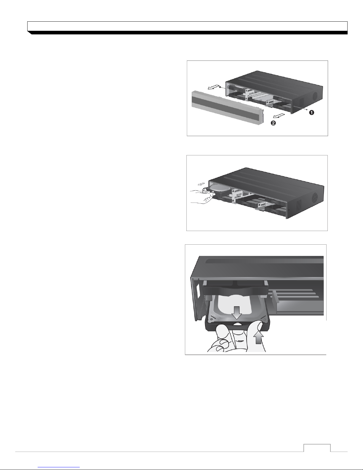
Using any unrecommended HDD may cause a system failure. Check the compatibility list and
use only compatible HDDs.
{A system failure or data loss caused by an incompatible HDD will void your warranty.}

4
OVERVIEW
CAUTION
Replaceable batteries
Risk of Explosion if Battery is replaced by an Incorrect type. Dispose of Used Batteries According to
the instructions.
Warning to service personnel
Double pole / neutral fusing.
Ethernet Instruction
This equipment is indoor use and all the communication wiring are limited to inside of the building or
similar word.
Key Features
This product is capable of receiving inputs from up to 16 channels of 1080P camera inputs of video
and audio recording onto a hard disk drive in real-time, as well as providing monitoring, playback
and backup footage in excellent quality of 1080P resolution.
It also provides transferring video and audio data to the networked external devices, which allows
remote monitoring environment for computers and mobile devices including cell phones.
Up to 16 channels of 1080P camera videos can be displayed at 480 / 400 fps in real-time.
Up to 16 channels of 1080P camera videos can be saved at maximum 480 / 400 fps.
Simultaneously recording and playback of maximum 16 channels (at 480/400 fps @ 2CIF).
Supports H.264 High Profile CODEC.
Auto alarm feature with self-diagnostics on the system (HDD S.M.A.R.T, network error, etc.)
Supports dual streaming for remote access service.
Supports HDD extension (eSTATA).
Various search methods (time, event, bookmark, thumbnail and text-in).
Mass storage backup via USB port or FTP server.
Supports remote access and search using web browser.
Dedicated smart phone applications that can be used with iPhone and iPad or on Android OS.
1080p Full HD GUI
Division
Display
Stream
Maximum performance (fps)
2CIF
4CIF
720P
1080P
1
1st stream
30
30
30
30
4
120
120
120
120
8
2nd stream
240
--
--
--
16
480
--
--
--

5
OVERVIEW
What's included?
Mouse Remote Control Power Cable
& Batteries (AAA x2)
DC12V Adaptor Adaptor cable retainer clip Screws fro HDDs
Terminal Block (9Px2) Terminal Block (10Px4) Quick Guide
User manual CD

6
OVERVIEW
Front Panel
Name
Description
IR Remote
Control
Receiver
Receive the signal from the remote control
USB
Used for connecting USB storage or mouse.
Status LED
Show the status of power, recording or network connection
together with the corresponding alarm.
HDD 1~5 /
eSATA
HDD1 HDD2 HDD3 HDD4 HDD5 eSATA
Indicates connection status of internal/external storage
devices.

7
OVERVIEW
Rear Panel
16 Channel
NO Name
Description
1
VIDEO IN
Video input terminal for cameras.
2
AUDIO IN
Port for audio input.
3
AUDIO OUT
Port for speaker connection.
4
ALARM IN
ALARM OUT
RELAY
RS-485
RS-232C
Alarm input signal port.
Alarm output signal port (TTL Level)
Relay Terminal output port.
Port for communication with external devices such as PTZ
camera and system keyboard.
Port for communication with external devices such as PTZ
camera, POS and ATM devices.
5
SPOT OUT
Exclusive port for SPOT output only (Connect to a TV monitor)
6
VGA
VGA monitor video output port.
7
HD MONITOR
HD monitor video output port.
8
eSATA
Connection port for external eSATA storage.
9
USB
Used for connection USB Storage or mouse.
10
WAN(UPLINK)
LAN(DOWN LINK)
Network port for connection to the Internet, router or hub
Reserved (DO NOT connect)
11
DC12V
Power input port.

8
OVERVIEW
Remote Control At a Glance
LOGOUT
Log out
POWER
Turn on or off the power.
PANIC
Start the emergency recording.
SEARCH
Display the search window.
ALARM
Show the alarm status with
a popup window.
ARCHIVE
Display the backup window.
SETUP
Display the system setup menu.
Channel
Function as channel selection
button in live or playback mode.
Or used for entering the password.
ID
Set the remote control ID.
DISPLAY
Switch the split mode.
SEQ
Switch to sequence mode.
SNAPSHOT
Take a snapshot of the video.
Used to change the direction
or adjust the play speed
in playback mode.
EXIT
Exit from the current screen
and return to the previous
screen.
ENTER
Select a menu item or apply
your settings.
LOG
Display the log list.
KEYLOCK
Lock any operation on the unit.
AUDIO
Display the audio channel
selection window.
RESERVE
Reserve the current video.
MENU
Display the tool bar on the live
screen.
Use to move through the menus
ZOOM/PTZ
Enter the digital zoom or PTZ
Mode and control the operation.

9
OVERVIEW
Change the remote control ID
The remote control will be active only if the remote control ID matches with that specified on the
DVR.
If multiple DVRs are installed on one place and you have just a single remote control, use the ID
button to set the remote control ID. Only the ID-matching DVR can be controlled.
1. From <SYSTEM> - <CONTROL DEVICE> under the System Setup menu, set the
<REMOTE CONTROLLER ID> and press <Apply>.
Select between 00 and 99. For more details, refer to <SYSTEM SETUP> in Operation
manual.
The remote control will be active only if the remote control ID matches with that of the
DVR's system ID.
2. Press the [ID] button on the remote control. The default remote control ID is 00.
3. Use the number buttons to provide a two-digit ID. If you want to enter 01, for instance,
enter the number 0 and 1 in sequence.
Check if the remote control ID is set properly by manipulating the remote control.
4. To reset the ID to 00, press and hold the [ID] button.

10
INSTALLATION
HDD Installation/Replacement
1. Remove 2 screws on both ends of DVR.
2. Pull the front side of the unit forward to
separate it.
3. Hold the middle of the HDD brackets
handle with index finger and pull it toward
while sustaining the bracket handle with
your thumb and middle finger as shown
in the illustration.

11
INSTALLATION
4. Once the HDD bracket is separated from
the main unit, remove 4 screws on both
ends of HDD bracket to separate the
HDD.
5. Install a new HDD and fasten 4 screws
back to both ends of the bracket to fix.
When installing HDD, make sure to
Install in the correct direction.
6. Push the bracket installed with new HDD
back into the main units it is completely
inserted.
7. Assemble the front panel back to the
unit.
When assembling the front panel to
the main unit, make sure the marked
part is tightly attached.
8. Fasten 2 screws on both ends of main
unit.

12
INSTALLATION
Basic Layout
Since the cable quality may affect directly to the video quality depending
on the distance between the camera and DVR, it’s recommended to
consult an authorized installer when installing the DVR.

13
INSTALLATION
Connecting to an external device
Connecting to the monitor
This product supports 1080p 60 Hz HDMI monitors and regular monitors that support DVI and VGA
inputs. Connect an HDMI cable to the port on the product’s rear bottom, or connect and HDMI-DVI
converter cable to connect a DVI monitor. Or, use VGA cable to connect the product’s with a VGA
monitor.
Once the product is set for NTSC or PAL output, connect cameras of the corresponding
video standard for proper operations.
Power Connection
Plug the provided DC 12V adaptor in the rear power port of the DVR.
For stable operation of the product, it is recommended to use the provided adaptor.
Make connection when the power is not applied yet.
Arrange up the cables and be careful not to peel off the cable coating.
Do not place the power cord under the carpet or rug. The power cord is usually earth-
grounded. However, even if it's not earth-grounded, do never modify it on your own for
earth-grounding.
Do not insert multiple devices in a single power socket. Otherwise, it may cause a power
overload.

14
INSTALLATION
Alarm I/O Connection
To connect the Alarm input signal
Connect the signal line of an alarm input device such as sensor to rear [ALARM IN] port
1. Loosen screws on both the alarm input port and [GND] of the terminal block plug.
2. Insert one end of alarm signal cable through [IN1] to [IN8] terminal hole, and then
fasten the screw.
3. Insert ground signal wire into the hole of the [GND] port, and tighten the screw.
4. To check proper insertion of the cable, gently pull the cable and test whether it
disconnects. To disconnet the cable, loosen the screw and pull out the cable.
To connect the Relay/Alarm output signal
Connect the signal line of an alarm output to rear [RELAY] port
1. Loosen the screws on the [NO] or [NC] port and [COM] port of the terminal bloack.
2. Insert the alarm signal wire into the hole of the [NO] or [NC] input, and tighten the
screw.
Check the relay type befere selecting a proper
NO (Normal Open) : normally Open but switching to Close if an alarm out occurs.
COM : Insert the grounding wire.
NC (Normal Close) : Normally Close but switching to Open if an alarm out occurs.
3. Insert the ground signal wire into the hole of the [COM] port and tighten screw.
Or, you can connect the signal cable of the alarm output device to the [ALARM OUT].
1. Loosen screws on [AO1] through [AO8] port and [GND] port of the terminal block.
2. Insert the alarm signal wire into the hole of the AO port and tighten the screw.
3. Insert the ground signal wire into the hole of the [GND] port and tighten the screw.
4. To check proper insertion of the cable, gently pull the cable and test whether it
disconnects. To disconnet the cable, loosen the screw and pull out the cable.
5. Install the wire-connected terminal block in the rear port.

15
INSTALLATION
Communication Port
RS-485 Connection
Connect a PTZ Camera of Keyboard Controller.
You can connect a text-in device such as POS or ATM.
After connecting the control device, be sure to match the connection settings between DVR and the
device. Refer to communication settings in “Operation Manaul”.
Connect three signals ([D+],[D-],[GND]) between DVR and of the control device by using
provided terminal block.
For RS-485 connection, refer to the user’s manual of the control devices.
There is two ports of RS485 on rear panel.
RS-485_1 : Connect Keyboard controller
RS-485_2 : Connect PTZ cameras
RS-232C Connection
You can connect PTZ cameras, POS or ATM devices.
For connection of the text-in device, refer to the user manual of the text-in device.
Audio Device Connection
You can connect an audio output device such as speaker amplifier.
Connect the audio input device such as microphone to the rear Audio In port, connect the audio
output device such as speaker amplifier to the Audio Out port.

16
INSTALLATION
Storage and Mouse Connection
eSATA Storage
If the storage space is insufficient, you can extend your storage capacity by adding an
eSATA storage device to the rear eSATA port.
Using devices other than recommended eSATA products may causes serious problem.
USB Device
You connect and use USB storage devices for backup of recorded video, saving snapshot,
firmware updating, importing/exporting user configurations. Also, USB mouse can be
connected for DVR manipulations.
If you need to connect a USB HDD with a high power consumption, it is recommended to
use a separate power source for that HDD.
External HDD
(For backup only)
USB Storage
Mouse

17
INSTALLATION
Network Connection
PC connection in the local network
You can connect DVR to a PC in the same network and control or manipulate it on the PC monitor.
1. Connect the [WAN(UPLINK)] port in the rear panel to the router or hub.
Do NOT connect any devices to the [LAN (DOWNLINK)] port.
2. Connect the local PC to the router or hub.
3. Enter the address in the Web browser of the local PC in the format of
“http://IP address:web service port ”. (Ex : http://192.168.1.23:8080)
The web service port is set to 8080 by default. From the Network Setup screen, you can c
hange the port number.
4. Provide the ID and password before logging in. Then, you can view the monitoring screen.
Access ID (factory default) : ADMIN, P/W : 1234.
For the security purpose, change the password before you use the product for the
first time after purchasing it.

18
INSTALLATION
PC connection from a remote network
You can connect DVR to a PC from a remote network and control or manipulate it on the PC
monitor.
1. Connect the [WAN(UPLINK)] port in the rear panel to the router.
Do NOT connect any devices to the [LAN (DOWNLINK)] port.
2. Connect the [WAN(UPLINK)] port of the router directly to the fixed IP LAN cable, or
connect it to the ADSL modem.
3. If using the router, set the port forwarding and enter the DDNS address in the address bar
(web browser) of the remote PC, or of the dedicated software program or mobile phone.
For the IP and DDNS address settings, refer “Operation manual”.
4. If the MAC address of the DVR is 00-1C-B8-12-34-56 and the web port number is 8080,
enter "http://001CB8123456.dvrlink.net:8080" in the address bar of the web browser.
If you have renamed DDNS as “mydvr”, you can make network connection at
http://mydvr.dvrlink.net:8080
Table of contents
Other Ganz DVR manuals

Ganz
Ganz CDR-01S User manual

Ganz
Ganz DR16NRT User manual

Ganz
Ganz DIGIMASTER DR-16FX5-3TB User manual

Ganz
Ganz PixelMaster PRO NR16H User manual

Ganz
Ganz Digimaster DR4N-Lite User manual

Ganz
Ganz AI BOX 4CH User manual

Ganz
Ganz DIGIMASTER DR4N User manual

Ganz
Ganz digimaster DR-4FX1 User manual

Ganz
Ganz DIGIMASTER SERIES User manual

Ganz
Ganz NR8-32M78 User manual

Ganz
Ganz DIGIMASTER SERIES User manual

Ganz
Ganz DigiMAster DR4H User manual

Ganz
Ganz ZR-DHC830NP User manual

Ganz
Ganz DR8NRT User manual

Ganz
Ganz digimaster DR-4FX1 User manual

Ganz
Ganz DIGIMASTER DR8HV User manual

Ganz
Ganz Digimaster Series DR8HRD User manual

Ganz
Ganz ZR-DHC1630NP User manual

Ganz
Ganz ZR-DH1621NP User manual

Ganz
Ganz ZR-DH1621NP User manual