8
SETTING CYCLE TIMERS AND AUTO-CLOSE TIMES
The control board has pre-set cycle times which are used to set the maximum time the controller will
drive the motors in the open and closed directions. The pre-programmed time for the open and close
cycle timer’s is 60 seconds. The control board also has a pre-set pedestrian access time of 5 seconds which
is intended to open the motor connected to M1 output only part way. If these default times do not suit
your needs simply use the procedure below to adjust them. ote the same procedure can be used to
adjust the auto-close times.
1. Place the slide switch into the “set” position
2. Adjust the timer’s value by pressing and holding the required push button for the desired time.
3. Repeat step 2 for the next timer (if desired).
4. Place the slide switch back into the “RU ” position.
5. Test operation.
Make sure that the slide switch is placed back into the “RU ” position before testing the new timer value.
As you can see the procedure used to set each timer’s value is the same only the push button used changes. Each
push button is clearly labelled underneath as to which timer’s value it sets. ote when setting the OPE , CLOSE
and PEDESTRIA cycle times the controller will drive the motors as if a “real” cycle is being executed. The
difference being that the motors will stop as soon as the button is released or the limit switches are reached. The
OP status LED on the control board will flash at 1 second intervals to assist setting times. ote when setting the
OPE and CLOSE cycle times when limit switches are used, release the push button a few seconds after the limit
switch cuts motor power. This allows for the motors to slow down over the life of the operators without the need
to adjust again
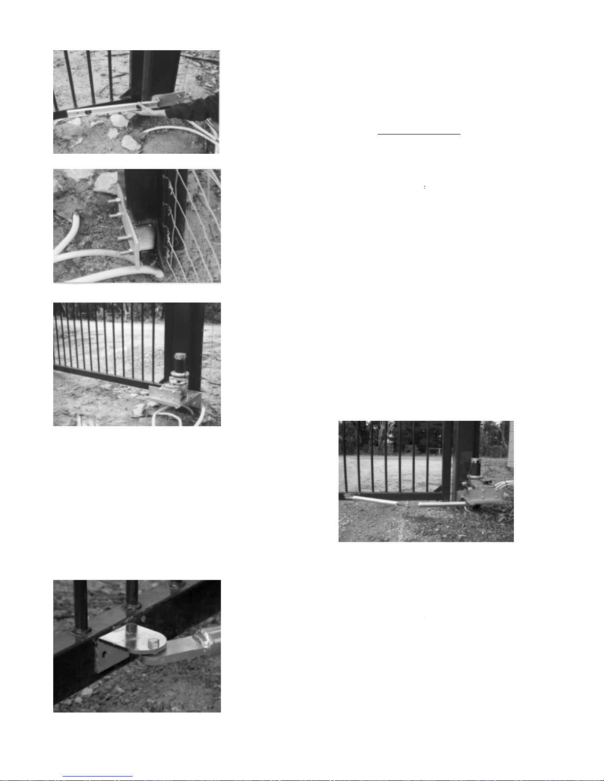
4. COMMISSIONING
•Position the gate so it is half way, tighten manual release knob to the point where the gate will just start to be
driven but the clutch will slip if the gate accidentally hits the gate stop too hard while setting up the limits.
•Power up board and with gate in the half way position, press transmitter or manual control switch so operator
drives gate.
•The first pulse will always open gate green open LED will flash (top right hand corner) if it does not, then
reverse two of the motor wires. Once the gate reaches its full open position, the green led will stay on, also
on closing, the red close led will flash while closing and then stay on once reaching it`s full open position.
•If dual gat s, leave one side disconnected (by putting both cams on limit switches) so adjustment can be done
on one side at a time. Once each side is set, you can run both gates together then do final adjustments to suit.
•Check which limit switch stops gate in each direction and adjust cams so gate will stop in the fully open and
closed positions.
•Limit switches should not switch off the gates too soon (before reaching the stops) and conversely not too late,
so the torque limiter is operating.
•Once happy with limits settings, now set the travel time. Change the run/set switch (mode selection 1 switch)
to set. Once in set, run the gate from either the full open or closed position by pressing either the opn (open),
or the cls (close) buttons. Keep the button pressed for the complete travel distance of the gate then release
approx 5 seconds after the gate has stopped in its full open or closed position. This has to done for both the
open and close cycles.
•Tighten manual release knob and check that the torque limiter slips if there is an obstruction in the way of the
gate but there is enough drive to overcome environmental conditions etc.
•Check that all safety devices work as designed and the external locks etc lock the gate.
•Install cover using screws screwed in the front and side to hold cover firm.