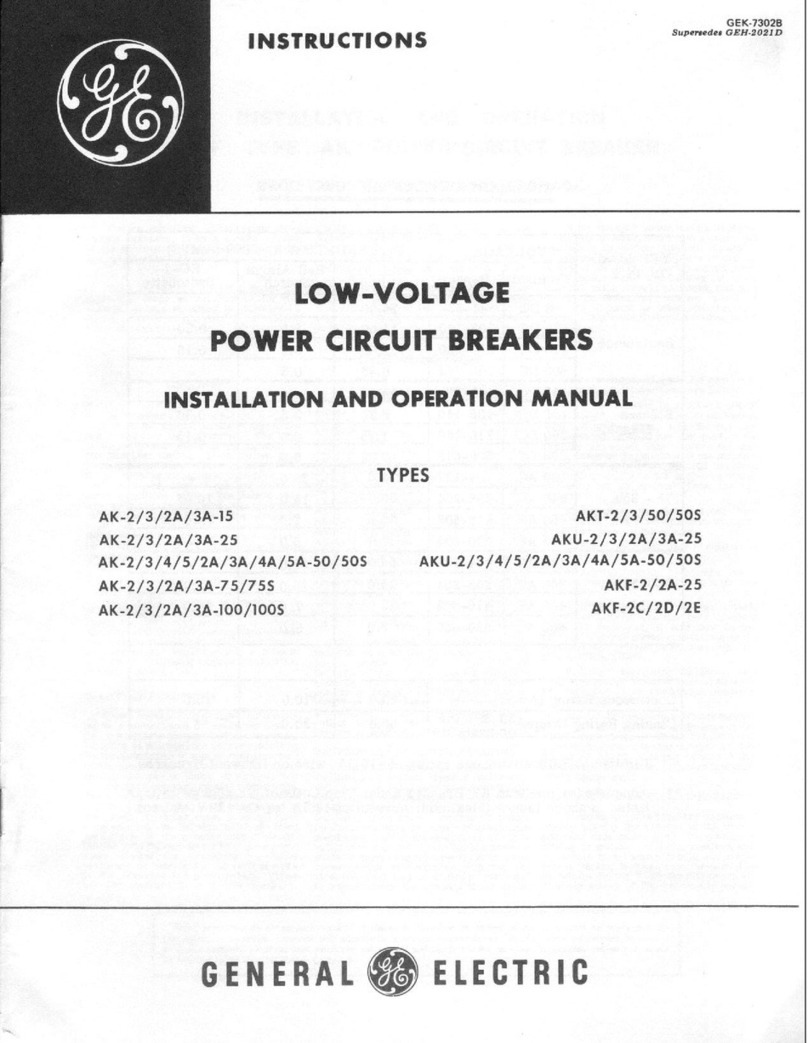
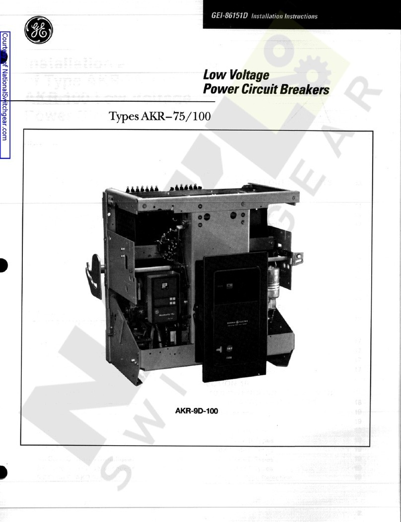
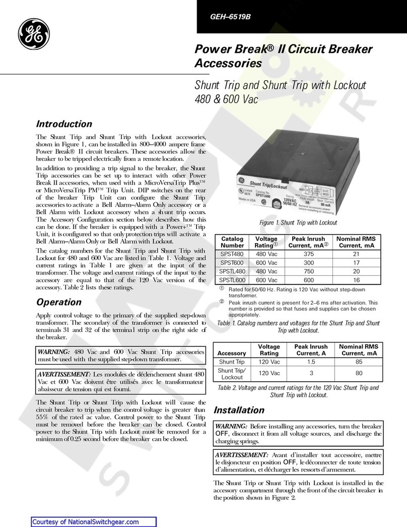
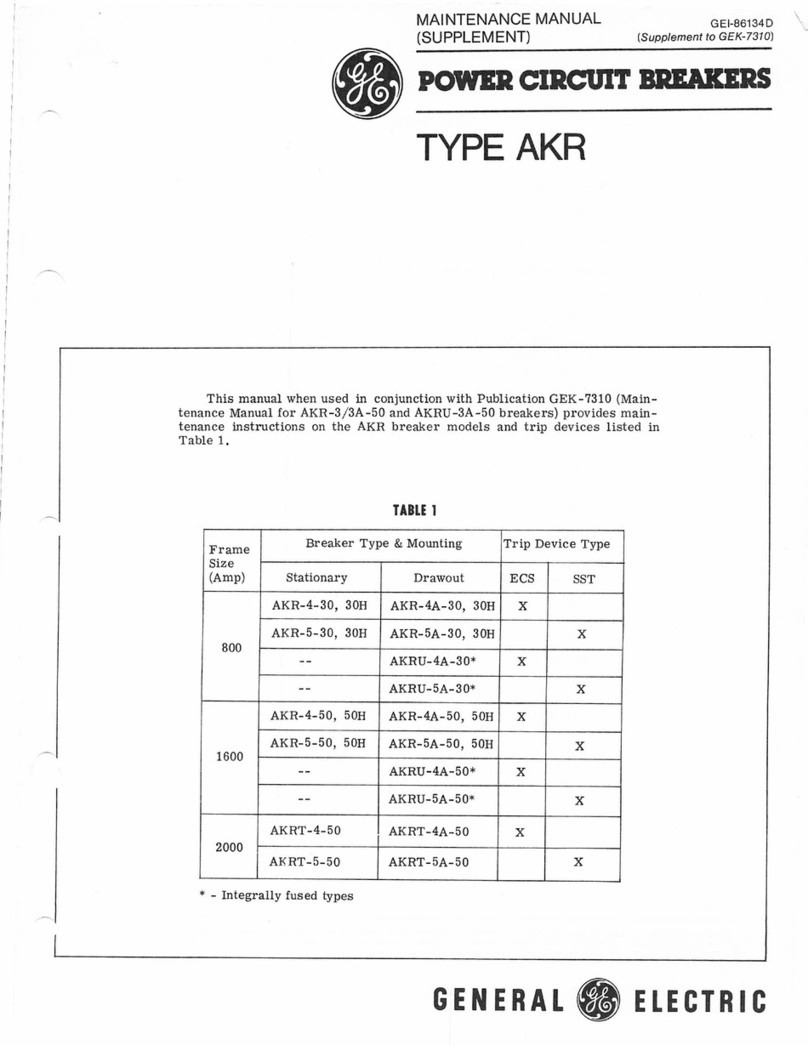
GE AKR User manual

Table
of
Contents
Description
Page
Introduction
Quick
Selector
Breaker
/
Trip
Combinations
. .
.
Quick
Selector
Replacement
Breakers
Breaker
/
Trip
Combinations
Breaker
Designations
Legend
Type
AKR
Breaker
Features
and
Characteristics
—
Manual
Operation
—
Electrical
Operation
Type
AKRU
Breakers
Enclosures
and
Mountings
MicroVersaTrip
®
RMS
-
9
Devices
Trip
Devices
—
Tripping
Functions
—
EC
Trip
Devices
DC
Applications
Accessories
—
OEM
Substructure
2
3
4
5
6
7
8
9
-
11
12
-
13
14
-
21
22
23
-
25
26
-
27
Ratings
Derating
Factors
Micro
VersaTrip
®
RMS
-
9
Current
Sensor
Ratios
AKRU
Fuses
Electrical
Characteristics
—
AKR
-
30
S
—
AKR
-
30
/
50
/
T
50
—
AKR
-
75
/
100
Wiring
Diagrams
Time
Current
Tripping
Characteristics
Time
Current
Curves
Outline
Drawings
Outline
Dimension
Drawing
Numbers
Weights
and
Formulas
Repetitive
Duty
Transformer
Short
Circuit
Current
Curves
Standards
and
References
Guide
Form
Specifications
Other
AKR
Circuit
Breaker
Publications
28
29
30
31
32
-
33
34
-
35
36
-
37
38
39
40
-
45
46
-
52
53
54
55
56
-
58
59
60
61
1
Courtesy of store.ips.us

Type
AKR
Low
Voltage
Power
Circuit
Breakers
The
General
Electric
line
of
Type
AKR
Low
Voltage
Power
capabilities
.
These
breakers
are
UL
listed
to
ANSI
stan
-
Circuit
Breakers
(
LVPCB
)
are
intended
for
use
in
commer
-
cial
,
industrial
,
and
utility
applications
.
Built
to
withstand
intense
service
conditions
,
these
circuit
breakers
provide
for
the
ultimate
in
system
selectivity
due
to
their
short
time
4000
Amperes
with
short
circuit
ratings
through
200
,
000
Amperes
.
dards
for
low
voltage
power
circuit
breakers
.
The
AKR
breaker
consists
of
five
frame
sizes
:
AKR
-
30
S
,
-
30
H
,
AKR
-
50
,
AKRT
-
50
,
AKR
-
75
and
AKR
-
100
;
800
through
AKR
-
50
AKR
-
75
AKR
-
30
H
AKR
-
30
S
2
Courtesy of store.ips.us

Quick
Selector
Breaker
/
Trip
Device
Combinations
Table
3.1
Ampere
Ratings
and
Overcurrent
Trip
Devices
600
V
ac
50
/
60
Hz
250
V
dc
Frame
Size
(
Amps
)
Frame
Size
(
Amps
)
Breaker
Type
Solid
State
Trip
Device
Electromechanical
Trip
Device
AKR
-
30
S
800
UVCAtOAD
cmam
RMS
-
9
Micro
Versa
Trip
TO
«
»
*
n
AKR
-
30
,
30
H
800 800
!
.
.
.
,
r
\
'
_
AKR
-
50
,
-
50
H
1600
2000
lOMG
Ttwr
0
*
1
A
*
WOUND
FAULT
FtCSUr
^
t
AKRT
-
50
H
2000
SHOAI
'
MM
T
.
«
*
•
*
Ml
i
r
AKR
-
75
3200
4000
*
*
>
»
*
TMt
wi
*
r
•
'
TIH
l
*
TOU
»
*
-
?
»
o
^
AKR
-
100
4000
6000
3
Courtesy of store.ips.us

Quick
Selector
Replacement
Breakers
Breaker
/
Trip
Device
Combinations
Table
4.2
Ampere
Ratings
and
Overcurrent
Trip
Devices
250
V
dc
600
V
ac
50
/
60
Hz
Frame
Size
(
Amps
)
Frame
Size
(
Amps
)
Solid
State
Trip
Device
Breaker
Type
Electromechanical
Trip
Device
(
•
MOfti
c
*
cmt
«
*
*
»
»
.
040
600
AK
-
25
600
RMS
-
9
Micro
Versa
Trip
W
ittfxCA
’
oa
to
.
i
«
.
»
-
MMCXIS
cummn
*
2000
AKS
-
50
1600
O
4
<
*
<
«
0
»
401
»
4
KKV
4
lO
*
U
tm
*
OtlA
*
AKST
-
50
2000
AMOdt
TMK
9
I
*
4
uti
a
»
t
«
rroiv
4000
AKR
-
75
3000
I
’
lOl
-
6000
AKR
-
100
4000
4
Courtesy of store.ips.us

Breaker
Designations
Legend
0
0
!
—
L
/
:
General
Type
Code
Frame
Size
in
Amperes
Code
dc
Old
style
LVPCB
AK
ac
25
600
600
AKS
AKR
replacement
for
AK
-
50
,
AKJ
-
50
30
S
800
AKRT
replacement
for
AKT
-
50
,
AKJT
-
50
AKST
30
,
AKSU
AKRU
replacement
for
AKU
-
50
,
AKJU
-
50
800
800
30
H
New
style
LVPCB
AKR
50
AKRT
2000
A
frame
1600
,
2000
2000
50
H
Integrally
fused
version
of
AKR
-
30
/
50
AKRU
75
3200
4000
100
4000
6000
Integrally
fused
version
of
AK
-
25
/
50
AKU
©
Suffix
D
is
affixed
to
AKR
designations
to
identify
non
-
automatic
dc
models
,
e
.
g
.
AKR
-
NB
-
30
D
Code
Mounting
Type
Code
Trip
Device
Type
Blank
Draw
out
AKD
Switchgear
EC
2
A
Draw
out
AKD
-
5
/
6
Switchgear
3
®
Power
Sensor
ECS
B
Draw
out
AKR
OEM
Substructure
4
®
5
®
SST
Draw
out
AKD
-
6
Switchgear
(
AKR
-
75
/
100
only
)
C
6
®
MicroVersaTrip
Draw
out
AKD
-
8
Switchgear
and
OEM
Substructure
MicroVersaTrip
®
RMS
-
9
7
D
Epic
MicroVersaTrip
8
S
Stationary
N
Non
-
automatic
33
"
Wide
Stationary
(
AKR
-
100
only
)
W
Discontinued
OEM
Substructure
AKR
-
75
/
100
only
)
F
A
-
Exam
iple
of
Nameplate
Designation
•
v
?
MicroVersa
-
800
A
Frame
Size
AKR
Trip
Type
Device
I
AKR
For
Draw
Out
Substructure
Mounting
5
Courtesy of store.ips.us

Type
AKR
Breaker
Features
and
Characteristics
Manual
Operation
Manual
Stored
Energy
Closing
AK
-
25
and
AKR
-
30
S
This
circuit
breaker
is
closed
by
first
rotating
the
handle
counterclockwise
approximately
100
degrees
;
this
resets
the
mechanism
and
partially
charges
the
closing
spring
.
Return
-
ing
the
handle
clockwise
to
the
normal
position
completes
the
spring
charging
and
drives
the
toggle
mechanism
over
-
center
,
closing
the
contacts
.
Manual
Opening
—
All
Breakers
All
breakers
,
manual
and
electrical
,
are
equipped
with
a
mechanical
TRIP
button
located
on
the
breaker
escutcheon
.
Manual
opening
is
accomplished
by
displacing
a
mecha
-
nism
latch
that
allows
the
toggle
linkage
,
which
holds
the
breaker
’
s
moveable
contacts
in
the
closed
position
,
to
collapse
.
Manual
Stored
Energy
Closing
AKR
-
75
and
-
100
This
circuit
breaker
requires
four
handle
strokes
to
charge
the
springs
.
Unlike
the
smaller
AKR
frame
sizes
,
the
break
-
er
’
s
contacts
close
during
the
fourth
handle
stroke
.
Initiation
of
closing
by
separate
close
button
is
not
available
.
Manual
Stored
Energy
Closing
AKR
-
30
,
-
50
and
AKRT
-
50
This
circuit
breaker
has
a
closing
spring
which
is
charged
by
a
number
of
handle
strokes
(
from
one
to
four
)
depending
on
the
angle
through
which
the
handle
is
rotated
.
Upon
comple
-
tion
of
the
charging
action
,
the
springs
are
"
propped
”
in
the
fully
charged
position
and
are
discharged
only
by
removing
the
“
prop
,
”
releasing
the
spring
to
close
the
breaker
.
Closing
is
initiated
by
depressing
a
mechanical
close
button
on
the
escutcheon
.
Courtesy of store.ips.us

Features
and
Characteristics
Electrical
Operation
Electrical
Stored
Energy
Closing
AK
-
25
and
AKR
(
U
)
-
30
S
This
electrically
operated
breaker
closes
whenever
the
closing
solenoid
coil
is
energized
.
This
causes
an
upward
movement
of
the
solenoid
armature
which
charges
the
springs
to
a
predetermined
over
-
center
point
for
closing
.
(
For
typical
electrical
circuit
see
pg
.
38
.
)
Electrical
Opening
All
breakers
,
manual
and
electrical
,
are
equipped
with
a
mechanical
TRIP
button
located
on
the
breaker
escutcheon
.
Electrical
breakers
include
a
shunt
trip
device
for
remote
opening
.
Electrical
Stored
Energy
Closing
AKR
-
30
,
-
50
,
-
75
&
100
This
electrically
operated
breaker
utilizes
a
motor
to
auto
-
matically
keep
the
closing
springs
in
a
charged
state
.
Whenever
the
control
solenoid
is
energized
,
its
operation
releases
the
closing
springs
,
closing
the
breaker
contacts
.
(
For
typical
electrical
circuit
see
pg
.
38
)
The
initiation
of
the
closing
operation
for
both
of
the
above
types
of
breakers
is
by
closing
of
a
contact
of
a
remote
switch
,
relay
or
a
close
button
in
the
front
escutcheon
if
the
breaker
is
so
equipped
.
The
breakers
control
schemes
have
an
anti
-
pump
feature
which
allows
only
one
closure
of
the
breaker
for
a
single
operation
of
the
closing
contact
no
matter
how
long
the
contact
may
be
held
closed
.
This
prevents
the
repeated
operations
that
would
ensue
if
one
of
the
automatic
trip
devices
was
activated
at
the
time
of
closing
.
A
manual
closing
handle
is
provided
for
maintenance
purposes
.
All
electrically
operated
breakers
close
within
five
cycles
.
7
Courtesy of store.ips.us

Type
AKRU
Breakers
device
trips
the
breaker
,
opening
all
three
poles
simultaneously
.
Individual
phase
indicators
pin
point
the
blown
fuse
.
The
breaker
remains
locked
out
until
the
fuse
is
replaced
and
the
device
is
reset
.
ary
mounted
fused
breakers
are
not
available
.
)
An
open
fuse
lock
out
device
is
an
integral
part
of
all
fused
power
circuit
break
-
ers
.
This
device
prevents
single
phasing
by
monitoring
the
fuses
.
Should
any
fuse
blow
,
this
direct
acting
as
an
integral
part
of
the
fused
draw
out
breakers
in
the
800
and
1600
Ampere
frame
sizes
.
The
3200
and
4000
Ampere
frames
are
available
with
coordinated
fuses
separately
mounted
in
a
draw
out
fuse
carriage
or
fuse
roll
out
element
(
station
-
The
fused
low
voltage
power
circuit
breaker
meets
NEMA
standard
SG
3
and
ANSI
C
37.13
,
and
C
37.28
.
They
provide
protection
for
sys
-
tems
with
available
fault
current
to
200
,
000
Amperes
RMS
symmetrical
.
Current
limiting
fuses
are
provided
AKRU
-
50
Fuses
Open
Fuse
Lock
Out
Indicators
8
Courtesy of store.ips.us

Enclosures
and
Mountings
Metal
-
Enclosed
Low
Voltage
Power
Circuit
Breaker
AKD
-
8
Switchgear
Type
AKR
draw
out
LVPCB
’
s
are
furnished
in
AKD
-
8
low
voltage
switchgear
with
integrated
short
circuit
ratings
.
The
equip
-
ment
is
designed
,
manufactured
and
tested
to
NEMA
SG
5
,
ANSI
C
37.20
.
1
and
UL
1558
.
AV
-
LINE
®
Switchboards
Type
AKR
breakers
are
furnished
as
stationary
mounted
or
draw
out
substructure
mounted
in
AV
-
LINE
®
switchboards
with
integrated
short
circuit
ratings
.
The
equipment
is
designed
,
manufactured
and
tested
to
NEMA
PB
-
2
and
UL
891
.
9
Courtesy of store.ips.us

Enclosures
and
Mountings
AKR
Breakers
for
OEM
Equipments
Type
AKR
breakers
,
both
for
stationary
and
substructure
draw
out
mounted
designs
are
available
,
and
are
UL
-
listed
to
ANSI
C
37.16
stand
-
ards
.
The
substructure
is
the
equipment
mounted
compo
-
nent
of
a
closed
-
door
draw
out
breaker
unit
.
Serving
as
the
stationary
receptacle
,
it
provides
means
for
mount
-
ing
and
connecting
(
both
primary
and
secondary
)
the
draw
out
breaker
(
removable
element
)
.
The
basic
sub
-
structure
is
a
self
-
contained
,
factory
-
aligned
frame
-
work
designed
for
convenient
mounting
as
individual
breaker
compartments
of
switchboard
or
switchgear
equipments
.
In
conjunction
with
a
line
of
accessories
,
tion
.
When
in
the
TEST
posi
-
tion
,
the
primary
disconnects
are
disengaged
,
but
the
secondary
disconnects
remain
engaged
.
This
per
-
ing
handle
is
inserted
through
the
breaker
escut
-
cheon
on
AKR
-
30
and
-
50
,
it
offers
the
equipment
builder
all
the
mechanical
and
electrical
components
necessary
to
outfit
a
com
-
partment
for
closed
-
door
draw
out
AKR
breakers
.
All
AKR
substructure
and
through
the
compart
-
ment
door
on
the
AKR
-
30
S
,
-
75
,
and
-
100
.
As
the
rack
out
mits
breaker
operation
with
-
handle
is
turned
,
it
rotates
breakers
(
draw
out
mounting
slotted
racking
arms
or
cams
circuit
.
In
the
DISCONNECT
type
“
D
”
for
AKR
-
30
and
-
50
on
each
side
of
the
breaker
and
type
“
F
’
for
AKR
-
75
and
100
)
are
equipped
with
extended
(
“
deep
”
)
escut
-
cheons
.
This
configuration
allows
the
breaker
to
be
racked
between
the
CON
-
NECTED
,
TEST
,
and
DIS
-
CONNECT
positions
without
the
CONNECTED
position
the
need
to
open
the
com
-
partment
door
.
On
all
frame
sizes
the
draw
out
mechanism
is
breaker
mounted
.
The
rack
-
out
energizing
the
primary
position
neither
primary
nor
secondary
disconnects
are
engaged
.
Breakers
may
be
racked
between
these
three
frame
.
The
cams
engage
fixed
pins
mounted
on
both
sides
of
the
substructure
,
moving
the
breaker
in
and
out
.
positions
with
the
compart
-
ment
door
closed
.
Each
position
is
clearly
identified
by
markings
which
appear
on
the
left
side
of
the
escut
-
cheon
as
it
emerges
through
the
door
cut
out
.
With
the
door
open
,
the
breaker
can
be
pulled
out
manually
from
the
disconnected
position
.
The
draw
out
operation
features
four
positions
.
In
the
primary
and
secondary
disconnects
are
fully
engaged
.
The
breaker
must
be
opened
before
it
can
be
racked
in
or
out
of
this
posi
-
Position
Indicators
on
Side
of
Breaker
Substructure
-
Mounted
Breaker
10
Courtesy of store.ips.us

Draw
Out
General
Purpose
Enclosure
—
NEMA
1
For
indoor
use
,
the
one
-
high
The
draw
out
mechanism
closed
door
draw
out
steel
housing
is
complete
with
a
draw
out
breaker
(
draw
out
mounting
type
letter
“
A
”
)
.
The
unit
is
wall
-
mounted
in
the
AKR
-
30
and
-
50
sizes
,
floor
-
mounted
in
the
AKR
-
75
and
-
100
sizes
.
The
draw
out
operation
features
the
same
four
posi
-
tions
and
functions
in
the
same
manner
as
described
earlier
for
draw
out
AKR
sub
-
structures
.
Breaker
position
,
though
,
is
clearly
identified
by
a
rotary
indicator
visible
through
a
door
opening
.
With
the
door
open
,
the
breaker
can
be
pulled
out
manually
from
the
DISCON
-
NECT
to
the
WITHDRAWN
position
so
that
the
breaker
is
completely
out
of
its
com
-
partment
and
ready
for
removal
.
is
externally
operated
by
a
removable
racking
handle
.
Two
mechanism
types
are
employed
.
A
breaker
-
mounted
,
screw
/
traveling
nut
type
services
the
AKR
-
30
and
-
50
frames
,
and
the
racking
handle
is
inserted
through
an
opening
in
the
breaker
escutcheon
.
The
equipment
mounted
type
mechanism
is
employed
on
the
AKR
-
75
and
-
100
models
(
mounting
type
“
A
”
break
-
ers
)
,
and
the
racking
handle
is
inserted
through
an
open
-
ing
in
the
leftside
of
the
door
.
In
both
mechanism
types
the
breaker
is
sup
-
ported
by
two
pins
protrud
-
ing
from
each
side
of
its
frame
,
these
engaging
slots
in
the
telescoping
rails
fas
-
tened
to
the
enclosure
walls
.
11
Courtesy of store.ips.us

MicroVersaTrip
®
RMS
-
9
Devices
the
protection
programmer
.
The
low
energy
signal
from
the
programmer
counteracts
the
strength
of
a
permanent
magnet
in
the
flux
-
shifter
,
al
-
lowing
a
spring
to
unseal
the
magnet
and
trip
the
breaker
.
that
cause
non
-
sinusoidal
currents
.
Therefore
,
the
solid
state
microprocessor
is
not
af
-
fected
by
component
toler
-
ance
and
does
not
require
compensation
for
signal
dis
-
tortion
.
Since
the
design
is
based
on
complimentary
metal
oxide
(
CMOS
)
tech
-
nology
,
it
is
less
sensitive
to
extraneous
noise
produced
by
lighting
,
instrumentation
,
radio
,
etc
.
The
solid
state
microproces
-
sor
technology
and
fast
ana
-
log
to
digital
converters
make
it
possible
to
measure
the
magnitude
of
the
phase
current
over
a
number
of
time
periods
within
the
cy
-
cle
.
The
RMS
-
9
sampling
rate
of
27
per
cycle
for
each
phase
allows
for
errors
of
less
than
1
%
on
systems
with
distortions
through
the
13
th
harmonic
.
This
digital
sampling
technique
pro
-
vides
the
most
accurate
system
protection
for
distri
-
bution
systems
that
include
ac
and
dc
variable
speed
drives
,
rectifiers
,
induction
heating
,
and
other
loads
The
RMS
-
9
MicroVersaTrip
system
for
AKR
low
voltage
power
circuit
breakers
con
-
sists
of
four
parts
:
plug
-
in
protection
programmer
,
flux
-
shift
trip
device
,
current
sen
-
sors
and
rating
plugs
.
The
programmer
contains
a
current
sensor
-
powered
,
solid
-
state
logic
unit
and
in
-
corporates
rotary
adjust
-
ment
switches
for
up
to
nine
functions
,
as
well
as
targets
for
mechanical
fault
trip
indi
-
cation
.
MicroVersaTrip
RMS
-
9
represents
the
latest
tech
-
nology
in
digital
solid
-
state
programmers
.
RMS
Digital
Sensing
of
Sinusoidal
and
Non
-
sinusoidal
The
RMS
-
9
provides
accu
-
rate
overload
protection
for
both
sinusoidal
and
non
-
sinusoidal
currents
by
direct
measurement
of
the
true
rms
content
of
the
current
wave
.
This
is
accomplished
by
microprocessor
digital
sampling
techniques
.
A
Full
Function
Trip
Unit
Available
with
Various
Combinations
of
Protection
Features
.
The
RMS
-
9
trip
line
of
pro
-
grammers
provides
maxi
-
mum
breaker
to
breaker
se
-
Current
Sensors
lectivity
and
custom
load
protection
.
Short
-
time
and
Ground
Fault
functions
in
-
clude
the
flexibility
of
coordi
-
nation
with
and
without
an
FT
ramp
.
Type
AKR
power
circuit
breakers
are
avail
-
able
with
High
Range
In
-
stantaneous
,
No
Instanta
-
neous
,
or
Switchable
(
OFF
)
Instantaneous
,
and
Ground
Three
toroidal
current
sen
-
sors
provide
maximum
flex
-
ibility
and
reliability
with
minimum
signal
error
.
Cur
-
rent
sensor
ratios
are
shown
in
Table
30.1
,
page
30
.
Rating
Plugs
Provide
Convenient
Flexibility
in
Matching
Load
Requirements
All
RMS
-
9
programmers
uti
-
lize
a
broad
range
of
field
installable
rating
plugs
for
for
tamper
-
proof
installation
,
future
uprating
capability
,
minimum
size
cable
selec
-
tion
,
and
an
extra
degree
of
coordination
flexibility
.
Fault
.
All
programmers
in
-
clude
a
clear
plastic
cover
with
provisions
for
sealing
Flux
-
shift
Trip
Device
The
flux
-
shifter
is
a
low
en
-
ergy
,
positive
action
tripping
device
that
is
automatically
powered
and
controlled
by
a
m
Fixed
Current
Sensor
Protection
Programmer
Flux
-
Shift
Trip
Device
MicroVersaTrip
®
RMS
-
9
System
Components
12
Courtesy of store.ips.us

SHORT
CIRCUIT
GROUND
FAULT
]
OVERLOAD
RMS
-
9
TfilR
VOtCATOR
PUSH
TO
Micro
Versa
Trip
E
-
OWAMMCM
CURRENT
SETTING
INSTAN
1
ANEOUS
PICKUP
*
»
t
i
l
•
I
21
rn
-
Nl
W
—
-
II
V
'
OM
,
%
10
*
III
111
\
1.11
LONG
TIME
DELAY
GROUNO
FAULT
PICKUP
JS
III
IV
*
«
9
4
«
I
•
1
#
\
/
A
>
'
*
v
.
it
-
-
(
VI
Q
9
f
M
45
SHORT
TIME
PICKUP
GROUND
FAULT
DELAY
I
2
TIN
I
*
TOUT
X
1
C
W
,
c
-
o
'
-
«
•
»
•
!
1
i
»
*
-
rc
X
^
msH
-
MVT
«
S
SNORT
TIME
OElA
*
I
'
TIN
"
*
T
OUT
*
AUHG
nUU
<
&
N
.
*
*
CAT
*
40
'
•
cn
/
om
:
M
i
t
TEST
G
M
%
run
A
c
*
r
«
o
1
>
S
4
HC
-
HUK
M
5
(
0121
/
J
I
Power
Supply
Board
Programmer
Faceplate
Logic
Board
XFMR
N
GROUND
FAULT
r
-
AMPLIFIER
SIGNAL
A
/
D
0
A
-
c
*
-
CONVER
-
RATING
PLUG
AMPLIFIER
TER
^
P
0
B
>
-
SRB
]
RATING
PLUG
AMPLIFIER
FACE
PLATE
SWITCHES
GF
0
C
-
w
-
LT
TRIP
1
RC
'
'
L
.
J
RATING
PLUG
ST
COMPARATOR
IOC
TRIP
COMPOSITE
E
*
D
Epic
MicroVersaTrip
Board
(
when
used
)
FLUX
SHIFTER
INST
SWITCH
MicroVersaTrip
*
RMS
-
9
block
diagram
.
13
Courtesy of store.ips.us

Trip
Devices
MicroVersaTrip
®
RMS
-
9
Programmer
Tripping
Functions
1
.
Current
Setting
—
Standard
2
.
Long
-
Time
Delay
—
Standard
3
.
Long
-
Time
Pickup
Light
—
Standard
4
.
Short
-
Time
Pickup
—
Optional
5
.
Adjustable
Short
-
Time
Delay
—
Optional
6
.
Instantaneous
Pickup
—
Standard
7
.
Ground
Fault
Pickup
—
Optional
8
.
Ground
Fault
Delay
—
Optional
9
.
Fault
Trip
Annunciator
(
Local
)
—
Optional
10
.
Rating
Plug
Not
shown
:
Adjustable
High
Range
Instantaneous
—
Optional
Zone
Selective
Interlock
—
Optional
The
quantity
of
these
func
-
tions
in
any
given
breaker
is
determined
by
complete
catalog
number
.
#
MicroVersaTrip
RMS
-
9
Programmer
14
Courtesy of store.ips.us

Table
15.1
MicroVersaTrip
®
RMS
-
9
Programmer
Function
Settings
Long
-
time
Short
-
time
Current
Setting
(
Multiple
of
Rating
Plug
Amps
)
Sensor
Rating
(
Amps
)
Max
.
Pick
Up
(
Multiple
of
Current
Setting
)
Pick
Up
(
Multiple
of
current
Setting
)
Frame
Size
Amp
Delay
0
(
Seconds
)
Delay
(
Seconds
)
(
S
)
Rating
(
X
)
(
C
)
<
C
)
.
5
,
.
6
,
.
7
,
.
8
,
.
9
,
.
95
,
1.0
,
1.1
Fixed
at
1.0
of
Current
Setting
2.4
,
4.9
,
9
8
,
20
AKR
-
30
S
AKR
-
30
H
150
,
400
,
800
800
.
5
,
.
6
,
.
7
,
.
8
,
.
9
,
.
95
,
1.0
,
1.1
Fixed
at
1.0
of
Current
Setting
2.4
,
4.9
,
9
.
8
,
20
FT
in
.
0
800
,
1600
AKR
-
50
1600
1.5
,
2.0
,
2.5
,
3.0
,
4
,
.
0
,
5.0
,
7.0
,
9.0
.
40
Fixed
at
1.0
of
Current
Setting
2.4
,
4.9
,
9.8
,
20
.
5
,
.
6
,
.
7
,
.
8
,
.
9
,
.
95
,
1.0
,
1.1
2000
AKRT
-
50
2000
l
2
!
out
®
.
10
,
.
21
,
.
35
.
5
,
.
6
,
.
7
,
.
8
,
.
9
,
.
95
,
1.0
,
1.1
2.4
,
4.9
,
9.8
,
20
Fixed
at
1.0
of
Current
Setting
3200
AKR
-
75
3200
Fixed
at
1.0
of
Current
Setting
2.4
,
4.9
,
9
8
,
20
.
5
,
.
6
,
.
7
,
.
8
,
.
9
,
.
95
,
1.0
,
1.1
4000
AKR
-
100
4000
Ground
Fault
Triple
Selective
Trip
,
Fixed
High
Range
Instantaneous
High
Range
Instantaneous
(
Multiple
of
Frame
Short
-
Time
®
Rating
)
Adjustable
Instantaneous
Pick
Up
with
ST
(
Multiple
of
Rating
Plug
Amps
)
Adjustable
Instantaneous
Pick
Up
without
ST
(
Multiple
of
Rating
Plug
Amps
)
Pickup
(
Multiple
of
Sensor
amp
Rating
)
Frame
Size
Delay
with
FT
(
Seconds
)
Delay
®
without
I
2
(
Seconds
)
®
®
(
X
)
(
H
)
(
X
)
(
S
)
+
0
.
2
,
.
25
,
.
3
,
.
35
,
.
4
,
.
45
,
.
5
,
.
6
•
4
,
.
6
,
.
8
,
1.0
AKR
-
30
S
AKR
-
30
H
1.5
,
2
,
3
,
5
,
7
,
9
,
10
.
13
,
15
1.5
,
2
,
3
,
5
,
7
,
9
,
10
22
kA
.
10
,
.
21
,
.
35
-
20
%
.
2
,
.
25
,
.
3
,
.
35
,
.
4
,
.
45
,
.
5
,
.
6
1.5
,
2
,
3
,
5
,
7
,
9
,
10
,
13
,
15
4
,
.
6
,
.
8
,
1.0
1.5
,
2
,
3
,
5
,
7
,
9
,
10
NA
.
10
,
.
21
,
.
35
AKR
-
50
.
40
at
200
%
of
pick
up
at
lower
limit
of
band
.
2
,
.
25
,
.
3
,
.
35
,
.
4
,
.
45
,
.
5
,
.
6
4
,
.
6
,
.
8
,
1.0
1.5
,
2
,
3
,
5
,
7
,
9
,
10
,
13
,
15
1.5
,
2
,
3
,
5
,
7
,
9
,
10
NA
.
10
,
.
21
,
.
35
AKRT
-
50
.
2
,
.
22
,
.
24
,
.
26
,
.
28
,
.
30
.
34
,
.
37
.
4
,
.
6
,
.
8
,
1.0
1.5
,
2
,
3
,
5
,
7
,
9
,
10
,
13
1.5
,
2
,
3
,
5
,
7
,
9
,
10
NA
.
10
,
.
21
,
.
35
AKR
-
75
.
2
,
.
22
,
.
24
,
.
26
,
.
28
,
.
3
4
,
.
6
,
.
8
,
1.0
1.5
,
2
,
3
,
5
,
7
,
9
NA
1.5
,
2
,
3
,
5
,
7
,
9
.
10
,
.
21
,
.
35
AKR
-
100
®
Triple
selective
trip
is
standard
when
long
-
time
/
short
-
time
only
is
required
.
®
Time
delay
shown
at
lower
limit
of
each
band
.
Ground
fault
pick
up
not
to
exceed
1200
amps
.
X
=
Rating
plug
amps
S
=
Sensor
amp
rating
C
=
Current
setting
H
=
Short
-
time
rating
®
Refer
to
Buy
Log
catalog
Table
1
page
6
-
3
for
frame
short
-
time
ratings
.
®
For
AKR
-
30
S
only
.
Table
15.2
MicroVersaTrip
®
RMS
-
9
Programmer
-
Available
Combinations
(
Add
Suffix
to
Basic
Catalog
Number
)
©
Time
delay
shown
at
600
%
of
cur
-
rent
setting
at
lower
limit
of
band
.
®
Time
delay
shown
at
lower
limit
of
each
band
.
All
pickup
tolerances
are
±
10
%
.
GF
®
Zone
Interlock
GF
/
ST
®
Zone
Interlock
Adj
.
Fixed
Switch
Inst
/
GF
OL
/
SC
/
GF
Targets
Ground
Fault
OL
/
SC
Targets
High
Adj
.
High
Short
-
Long
-
Programmer
Suffix
Inst
.
Inst
.
time
Inst
.
time
(
Z
2
)
(
T
2
)
(
Z
1
>
(
X
)
(
G
)
(
T
1
)
(
H
)
(
K
)
(
S
)
(
»
>
<
L
)
Adjustable
Instantaneous
X
X
L
1
X
X
X
LIT
1
X
X
X
X
LIGT
2
LIGT
2
Z
1
LSIT
1
LSIGT
2
LSIGT
2
Z
1
LSIGT
2
Z
2
X
X
X
X
X
X
X
X
X
X
X
X
X
X
X
X
XX
X
X
X
X
X
X
X
Adjustable
High
Instantaneous
X
X
X
X
LSHT
1
LSHGT
2
LSHGT
2
Z
1
LSHGT
2
Z
2
X
XX
X
X
X
X
X
X
X
X
X
X
X
X
X
X
Fixed
High
Instantaneous
®
X
X
X
X
LSKT
1
LSKGT
2
LSKGT
2
Z
1
LSKGT
2
Z
2
X
X
X
X
XX
X
X X
X
X
X
XX
X
X
X
No
Instantaneous
©
X
X
X
LST
1
X
X
X
X
LSGT
2
LSGT
2
Z
1
LSGT
2
Z
2
X
X
X
X X
X
X
X
X X
Switchable
Instantaneous
/
Ground
Fault
©
®
X
X
X
X X
X
LSIGT
2
X
'
©
Not
available
for
AKD
-
7
D
-
30
S
or
AKRU
-
7
D
-
30
S
.
®
Only
available
for
AKR
-
7
D
-
30
S
or
AKRU
-
7
D
-
30
S
.
®
Requires
zone
selective
interlock
module
types
TIM
1
(
120
V
ac
control
voltage
)
or
TIM
2
(
125
V
dc
control
voltage
)
.
®
Not
UL
Listed
.
Courtesy of store.ips.us

Trip
Devices
MicroVersaTrip
®
RMS
-
9
Tripping
Functions
Long
-
Time
Function
Moving
from
left
to
right
on
the
current
axis
,
Figure
16.1
,
the
upper
part
of
the
time
current
curve
is
the
long
-
time
pickup
.
This
is
the
func
-
tion
used
to
protect
a
circuit
against
low
magnitude
over
-
currents
.
The
breaker
trips
because
the
current
has
exceeded
the
long
-
time
setting
.
If
a
breaker
is
pro
-
tecting
a
motor
,
the
start
-
up
surge
(
in
-
rush
current
)
can
be
accommodated
by
setting
the
breaker
to
allow
for
a
momentary
delay
while
the
motor
has
a
chance
to
reach
its
normal
operating
speed
or
full
load
current
.
CURRENT
SETTING
7
X
8
X
LONGTIME
PICKUP
.
S
t
7
.
1.1
1
DELAY
MO
MO
MO
to
*
>
g
Tim
#
Delay
Bands
t
>
>
/
MO
7
400
7
MO
Maximum
Total
Clearing
Tim
#
WO
l
2
T
OUT
Minimum
Toial
Clearing
Tim
#
IDO
?
A
10
TO
10
5
C
90
Short
-
Time
Function
The
middle
portion
of
the
curve
is
the
short
-
time
func
-
tion
.
It
is
used
to
protect
against
higher
magnitude
overcurrents
and
low
-
level
short
circuit
faults
.
Overcur
-
rent
due
to
short
circuits
is
generally
in
the
order
of
10
or
more
times
full
-
load
cur
-
rent
,
and
is
measured
as
symmetrical
RMS
(
root
mean
square
)
short
-
circuit
current
.
40
M
v
w
20
VM
SHORT
TIME
/
0
UT
SHORT
TIME
VI
l
PICKUP
<
2
i
DELAY
10
M
9
Short
Tm
*
WlJfJfL
li
'
oK
VK
in
g
§
‘
•
4
.
'
.
^
Pt
IN
56
UJ
VI
3
2
i
'
*
•
i
I
I
I
Instantaneous
Function
At
the
bottom
of
the
time
current
cun
/
e
is
the
protect
-
ive
device
’
s
instantaneous
function
.
The
instantaneous
trip
point
determines
the
level
at
which
the
breaker
will
trip
without
an
intentional
time
delay
.
This
immediate
interruption
occurs
only
as
a
result
of
a
severe
overcur
-
rent
condition
,
such
as
a
high
-
level
short
circuit
,
that
would
damage
the
electrical
system
if
not
interrupted
.
An
instantaneous
trip
can
be
adjustable
,
depending
upon
the
application
.
i
.
9
'
BL
8
>
z
.
01
0
*
0
T
04
M
A
[
HMirai
.
04
Deifm
.
ir
'
End
ol
Cur
*
4
03
03
ZZ
/
Z
/
/
y
/
.
5
.
»
?
MULTIPLES
OF
INSTANTANEOUS
PICKUP
MUlTlPl
ES
OF
CURRENT
SETTING
(
C
)
Fig
.
16.1
Time
Current
Curve
Definition
—
Overload
and
Short
Circuit
i
f
16
Courtesy of store.ips.us

Ground
Fault
Protection
A
ground
fault
is
uninten
-
tional
current
flowing
from
a
circuit
through
a
conducting
path
to
ground
.
It
is
usually
l
*
t
Function
An
l
2
t
function
is
available
with
MicroVersaTrip
.
®
This
provides
a
ramp
function
(
l
2
t
=
constant
)
in
the
short
-
time
and
ground
fault
char
-
of
a
low
magnitude
{
less
acteristic
(
See
Fig
.
16.1
)
that
allows
maximum
coor
-
value
)
and
not
sensed
by
the
dination
with
downstream
thermal
-
magnetic
protective
modern
electronic
trip
devices
that
follow
a
curve
instead
of
a
square
path
.
The
l
2
t
function
also
allows
tighter
motor
protection
by
accommodating
the
tran
-
sient
inrush
while
the
short
-
time
pickup
remains
just
slightly
higher
than
the
steady
state
starting
current
.
In
other
words
,
the
path
fol
-
plex
collection
of
external
lows
the
hypotenuse
in
-
stead
of
the
right
angle
.
When
the
square
short
-
time
ground
fault
and
signal
a
path
might
intersect
with
a
downstream
fuse
or
breaker
,
the
l
2
t
function
per
-
delay
bands
with
l
2
t
in
and
mits
the
short
-
time
delay
path
to
veer
in
front
of
the
time
current
curve
for
the
8
8
2
S
4
$ $
7
|
*
10
H
.
1
-
t
.
7
M
I
I
»
H
51
B
)
0
HN
:
ltd
7
Ml
toe
/
700
MO
r
/
MO
GROUND
FAULT
/
PICKUP
IDO
y
'
A
than
the
long
-
time
pickup
200
protective
device
.
Using
/
100
«
0
'
•
0
devices
,
protection
against
ground
faults
can
be
built
into
a
distribution
protection
system
with
ground
fault
pickup
and
delay
functions
added
to
the
circuit
break
-
er
’
s
fault
interrupting
capa
-
bility
.
Before
electronic
trips
came
on
the
scene
,
a
com
-
70
«
0
so
40
'
'
lauiLr
30
'
-
/
20
/
X
V
GROUND
FAULT
DELAY
!
*
T
IN
l
*
T
OUT
10
7
I
7
MAX MAX
/
'
/
6
1
/
7
in
5
relays
and
current
sensors
were
needed
to
sense
a
a
V
z
V
,
o
«
/
/
IA
/
z
/
u
breaker
to
trip
.
Eight
ground
fault
pickup
levels
and
three
m
%
^
m
in
in
IN
our
i
KB
9
out
to
allow
full
selectivity
,
insuring
that
only
the
breaker
closest
to
the
downstream
device
.
Without
ground
fault
will
trip
.
Addi
-
this
function
,
coordination
and
selectivity
would
be
dif
-
locking
for
the
ground
fault
ficult
to
attain
.
SIS
OUT
SIS
1
Y
A
SS
SIS
!
KZ
res
g
5
f
5
*
r
<
tVPCB
MC
a
.
icce
Mai
4
55
cx
*
L
tion
of
zone
selective
inter
-
>
C
LVPC
8
MC
S
ICCB
i
x
V
,
\
N
A
r
XX
4
,
J
ivpce
MC
.
&
ICCB
suss
Hi
BSSSSSSSS
*
function
further
enhances
1
v
\
\
\
this
protection
by
permitting
"
timed
”
tripping
and
closer
back
-
up
protection
.
x
.
\
i
0
»
Dt
01
M
.
05
0
»
.
0
)
.
02
.
01
I
4
S
•
7
•
I
10
20
30
40
10
ID
701
DM
s
i
7
i
a
Fig
17.1
Time
Current
Curve
Definition
Ground
Fault
17
Courtesy of store.ips.us

1
Type
AKR
Breakers
Trip
Devices
MicroVersaTrip
®
RMS
-
9
Tripping
Functions
i
Current
Setting
(
Standard
)
The
adjustable
current
setting
determines
the
nominal
long
time
current
setting
with
a
±
10
%
band
width
.
With
a
1.1
setting
the
breaker
will
carry
indefinitely
without
tripping
the
rating
plug
rating
.
Changing
the
setting
changes
the
nominal
current
rating
for
the
breaker
.
CURRENT
SETTING
9
X
95
X
1.0
X
N
SETTING
(
C
)
N
N
N
Long
-
Time
Delay
(
Standard
)
This
long
-
time
delay
adjust
-
ment
varies
the
time
it
will
take
the
breaker
to
trip
under
sustained
overload
condi
-
tions
.
It
provides
the
function
of
withstanding
momentary
overloads
such
as
motor
starting
,
welding
,
or
other
overcurrent
conditions
with
-
out
interrupting
the
service
.
LONG
TIME
DELAY
DELAY
Long
-
Time
Pickup
Light
(
Standard
)
The
long
-
time
pickup
light
provides
visual
indication
that
the
breaker
is
experi
-
encing
an
overload
condi
-
tion
.
Indication
is
provided
by
a
light
-
emitting
diode
(
LED
)
which
is
only
activated
prior
to
trip
-
out
and
during
long
-
time
time
-
out
.
Saves
test
and
system
start
up
time
.
RATING
PLUG
CAT
.
NO
.
TR
20
S
2000
TEST
X
-
2000
A
S
-
2000
A
•
6
PICKUP
PICKUP
Short
-
Time
Pickup
(
Optional
)
This
short
-
time
pickup
adjustment
controls
the
level
of
high
current
the
breaker
can
carry
for
short
periods
of
time
without
tripping
.
Per
-
mits
downstream
breakers
to
clear
short
circuit
faults
without
tripping
out
the
upstream
protective
device
.
SHORT
TIME
PICKUP
SHORT
-
TIME
PICKUP
18
Courtesy of store.ips.us

Short
-
Time
Delay
(
Optional
)
The
short
-
time
delay
adjust
-
ment
is
used
in
conjunction
with
the
short
-
time
pickup
setting
to
provide
a
further
refinement
of
coordination
between
circuit
breakers
.
It
establishes
the
time
interval
the
breaker
will
wait
before
responding
to
the
short
-
circuit
current
level
selected
on
the
short
-
time
trip
point
adjustment
.
SHORT
TIME
DELAY
I
2
T
OUT
DELAY
The
instantaneous
trip
point
determines
the
level
at
which
the
breaker
will
trip
without
intentional
time
delay
(
0.025
seconds
or
less
)
.
This
immediate
inter
-
ruption
occurs
only
as
a
result
of
a
severe
overcur
-
rent
condition
,
thereby
mini
-
mizing
damage
to
the
electri
-
cal
system
and
equipment
.
Adjustable
Instantaneous
Pickup
(
Standard
)
INSTANTANEOUS
PICKUP
INSTANTANEOUS
PICKUP
19
Courtesy of store.ips.us
This manual suits for next models
10
Table of contents
Other GE Circuit Breaker manuals

GE
GE AM-13.8-500-5C User manual

GE
GE SPST012 User manual

GE
GE CB Watch 3 User manual

GE
GE GSTG024D User manual

GE
GE ReliaGear Pro-Stock Spectra RMS User manual

GE
GE AKR-30 Series User manual

GE
GE Power Break II User manual

GE
GE MicroVersaTrip AKR-75 User manual

GE
GE ML-14-0 User manual

GE
GE Pro-Stock SF250 User manual

GE
GE SPST480 User manual

GE
GE AM-4.16-250-9 User manual

GE
GE AM-4.16-250-6 User manual

GE
GE AK-2-15 User manual
GE
GE EntelliGuard L User manual

GE
GE MicroVersa Trip Plus User manual

GE
GE AK-2-15 User manual

GE
GE Power Break II User manual

GE
GE MicroVersaTrip AK-50 User manual

GE
GE A Series Pro-Stock THQB User manual