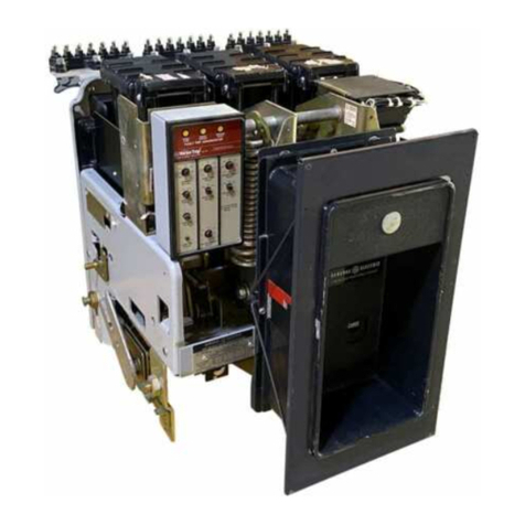
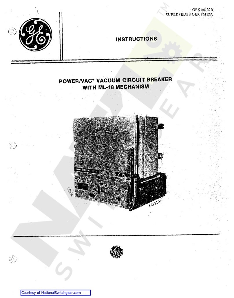
GE AK-2-15 User manual

INSTRUCTIONS GEK-73028
Super8edes
GEil-2021
D
LOW-VOLTAGE
POWER CIRCUIT BREAKERS
INST!'LLATION
AND
OPERATION
MANUAL
AK-2/3/2A/3A-15
AK-2/3/2A/3A-25.,"
'
AK-2/3/4/5/2A/3A/4A/5A-50/50S
AK-2/3/2A/3A-75/75S
AK-2/3/2A/3A-100/100S
TYPES
AKT-2/3/50/505
AKU-2/3/2A/3A-25
AKU-2/3/4/5/2A/3A/4A/5A-50/SOS
AKF-2/2A-25
AKF-2C/2D
/2E
GENERAL.
ELECTRIC
Courtesy of NationalSwitchgear.com

AUXILIARY DEVICES SPECIFICATIONS
TYPE
LOAD VOLTAGE INTERRUPTING RATING (AMPS)
OR
P.
F.
Auxiliary
Bell
Alarm
EC-1
Nominal Range Switch Switch Switchette
48
DC
41-56
25.00 - -
125
DC'
106-140 11.00 2.5 0.30
Resistance
250
DC
210-280 2.00 0.9 0.15
--
600 DC 508-672 0.45 0.3 -
48
DC
41-56
15.00 - -
--
<
Electro-.
125
DC
106-140 6.25 2.5 0.30
Magnet 250
DC
210-280 1.75 0 9 0.15
600
DC
508-672 0 35 0 3 -
120
AC
104-127 75.0 .
30.0 -
75
-
85%
240
AC
208-254 50.0 15.0 10.0
Lagging 480
AC
416-508 25.0
'7
0 10.0
.,500
AC
520-635 12.0 5.0 -
120
AC
104-127 50.0 30.0 -
30 -
35%
240
AC
208-254 25.0 15.0 10.0
Lagging 480
AC
416-508 12.0
7,0
10.0
600
AC
520-635 8.0
5.0
-
--
--
Continuous Rating (Amps) *20.0 *10.0 *10.0
Closing Rating
(Amps)30-35~"~;F
50.0 30.0
**
or
~
00
ive
*
Limited
to
5.0A
continuous
rating
of #16GA.
wire
on
Drawout
Breakers.
**
Adequate
for
use
with
AK
Breaker
Shunt
Trip
Coils of
the
voltage
ratings
listed
in above
table.
(Maximum
current
of
12
.3A
for
the 120 V.
AC
coil)
Courtesy of NationalSwitchgear.com

INSTALLATION AND OPERATION
OF
TYPE
AK
POWER CIRCUIT BREAKER
RECEIVING,
HANDLING
AND
STORAGE
Before installing
or
operating these
circuit
breakers,
make a careful reading
of
the sections
of
these instructions which
are
pertinent
to the anticipated work.
Upon
receipt
of
a
circuit
breaker,
im~
mediately make an examination for any
damage or loss sustained ln shipment.
If
injury,
loss
or
rough handling
ts
evident,
ftle a damage claim
at
once with the transM
LOCATION
In choosing a location
1
f.or
the installa-
tion
of
an-
AK
Circuit
Breaker,
there
are
two
factors
to be considered, The
first
of
these
is
the effect
of
the location
on
the
breaker
ltseU. Much better
per~
formance and longer life may be expected
U the
area
ls
clean, dry
dust~free,
and
well ventilated, than:
if
the opposites to
these conditions exist. The second con-
sideration
is
convenience for operation
and maintenance, The
breaker
should be
easily acicesslble
to
the operator, and
there
should be sufficient space allowed
for maintenance work to be ,pone
if
this
becomes
necessary.
MOUNTING
AK
Circuit
Breakers
are
designed to
be mounted in any one
of
three
ways.
These
are
dead front mounting, individual
mounting with the enclosurebeingprovided,
and drawout mounting in which the breaker
is
designed for insertion into a cubicle
in drawout equipment such as a substation
or control board.
DEAD FRONT BREAKERS
These
breakers
are
designedfor mount-
ing in a swttchboard
or
enclosing case
Of
the
customer's
design and construction.
Mounting ln this instance consists
of
bolting
the
breaker
frame to a supporting
structure
within the switchboard or enclosure,
con~
necting the power buses or. •cables and
making any
necessary
control cdnnechons.
'rhe front cover
of
the
breaker
enclosure
may be a hinged door or a plate bolted
to
the panel.
In
either
case,
it
should have
a section cut out, thiOugh which the front
escutcheon
_of
the_
br_eaker may protrude.
Outline 'drawing· numbers
glVing
the dimen-
sions needed for
preparing
a suitable
enclosure
or
cubicle for the various types
of
AK
breakers
are
given below. These
are
for standard 2 or 3 pole
breakers.
portaUon company and notify the
nearest
General Electric Sales Office.
Unpacli;:
the
circuit
breaker
as
soon
as
possible after
tt
has been received.
Exer~
else
care
in the unpacking to avoid damage
to
the breaker
parts.
Be
sure
that
no
loose
parts
are
missing
or
left in the packaging
material. Blow out any
dirt
or
loose
parti-
cles
of
packaging material
rematnlngon/or
in the breal{er.
INSTALLATION
Breaker_
AK-2~15
and 25
AK-3-15 and
25
AK
..
2-50
Man.
Oper.
AK-2-50
E!ec.
Oper.
AK~3~50
Man. Oper.
AK~3~50
Elec. Oper.
AKT-2-50
Man.
Oper,
AKT-2p50 Elec, Oper,
AKT-3~50
Man,
Oper.
AKT-3-50
Elec.
Oper.
AK-2-75
Man. Oper,
AK-2-75
Elec.
Oper
AK-3-75 Man. Oper
AK-3-75
Elec,
Oper.
AK
..
2-100 Man. Oper.
AK-2-100
Elec,
Oper.
AK-3-100
Man.
Oper.
AK-3-100
Elec.
Oper.
AK-4-50
Man, Oper.
AK-4-50
Elec.
Oper.
AK-5-50
Man,
Oper.
AK-5-50
Elec. Oper.
Typical Outline
Drawing
No.
695Cl16
121C'7570
845C281
238C123
121C7553
121C7555
102C3650
102C3651
121C7589
121C7590
845C284
269C225
121C7583
12!C7557
845C290
269C227
121C7585
!21C7559
134C2600
!34C2601
134C26!0
134C2611
The surface
on
which the
breaker
is
mounted must be flat throughout in
order
not to impose
any
internal distortion
on
the
breaker
unit, The supporting
structure
must be rigid enough to avoid
any
pos~
sibility
of
the
breaker
studs supporting the
weight
of
the
breaker,
Minimum cutout
dimensions, as given
by
the appropriate
outline drawing, must be maintained
to
provide adequate
electrical
clearance.
INDIVIDUALLY ENCLOSED BREAKERS
Individually enclosed
breakers
are
supplied with
several
types
of
enclosures,
most common is the generalpurpose type
or
the weather
resistant
type, The
former
is
used
for
favorable indoor locations
and
the
latter
for outdoor locations
or
indoor
locations that may be subjecttounfavorable
conditions, All
of
the enclosures
are
pron
vtded with suitable means
for
mounting
on
walls
or
supporting framework. Removable
cover plates
are
supplied with the en-
closures which may be drUled
or
machined
to accommodate the entrance
of
bus ducts,
If
the
circuit
breaker
is
notto be placed
in
service
at
once,
store
it
tn a clean,
dry
location in an upright position. Support
it
to
prevent bending
of
the studs or damage
to any
of
the
breaker
parts.
Do
not cover
the breaker with any packing
or
other
material which absorbs moisture, that may
cause corrosion
of
breaker
parts.
A
covering
of
kraft
or other non-absorbent
paper will prevent dust·from settling
on
the -
breaker.
conduits
or
cables. Steps in the procedure
for installing enclosed
breakers
follow:
1.
If
the breali;:er is an AK-15, AK-25
or
an AK- 50, remove
it
from the enclosure.
Witli AK-50
breakers,
a handle and cam
arrangement is used
for
that
part
of
the
breaker
movement that involves the dis
..
engagement
or
engagement
of
the
primary
disconnect.
AK~75
and AK-100
breakers
are
bolted solidly to the enclosure
frame
and need not be removed from
~he
en-
closure,
2. Remove cover plates
of
enclosure
and
prepare
them
to
accommodate whatever
power entrance means
is
used.
3,
Mount
enclosing case to supporting
structure,
4. Replace cover plate and make
power connections
to
stationary
terminals
in enclosure,
5,
If
the
breaker
is a type AK-15,
AK-25
or
AK~50
and has ·been removed
from the enclosure, it inay
now
be
re-
placed. Control power connections
to
the
terminal board should be made as
req\.~lred,
(See CONNECTIONS),
6. Before energizing the power
cir
..
cult, opel'ate the
breaker
several
times
to
be
sure
that
it
is
fUnctioning ·properly.
(See OPERATION),
AK-4/5.
50
breakers
Which avo
indlvid·
ually enclosed will have enclosures
of
the
AKD5
drawout type, These
breakers
will
be straightdrawout
breakers,
typesAK-4A-
50
and
AK~5A-50.
(See instructions in
this
book under the heading,
11
Drawout
Breakers
AKD5 Equipment'')
DRAWOUT BREAKERS
AKD
EQUIPMENT
Mounting drawout
breakers
consists
of
simply placing the
breaker
in the
proper
position with
respect
to
its
enclosure,
sliding
or
rolling
it
to a stop position, and,
by
means
of
a racking handle and mech
..
anism, racking
it
through the
last
part
of
its
moven1ent during which the stationary and
movable halves
of
the disconnects engage.
The$e
inslruction$ do
nol
purport
lo cover
all
detail$
or
variations
in
equipment
nor
lo
provide
for every pouible
contlntJency
lo
be met
In
connecflon
with
instal/cdion, operallon
or
maintenance.
Should
further
information
be de$ircd
or
should
particular
problems arise
which
are
not
covered sufficienfly for
the
purchaser'1
purpose1,
the
matter
should
be
reFerred
to
the
General
Electric;
Company.
3
Courtesy of NationalSwitchgear.com

GEK
..
7302
Installation and Operation
of
Type
AK
Power
Circuit
Breakers
Large
drawout
breakers
are
fastened to a
telescoping
tray
which extends out
from
the
enclosure to
receive
the
breaker.
Small
breakers
have guides on
their
side
plates
which
slide
in channels in the
enclosures.
Both
large
and
small
breal.ters have a
test
position in which the
secondary
disconnects
are
engaged, but the prime.ry
d~sconnects
are
not. In
this
position, the
breaker
may
be operated
electrically
without energizing
the load cable
or
bus.
Use
D50H47
lubricant
on
thedisconnE!ct
terminals
to reduce the force
required
to
insert
the
breaker.
!~g
Breaker
AK-15 and 25
1.
Trip
the
breaker.
2.
Raise
the break:er unttl the guides
on
the
sides
of
the
breaker
al'e level with
their
mattng supporting channels in the
enclosure, and sllde the
breaker
part
way
into
its
enclosure. (Note -The
breaker
will be obstructed
by
a position stop at the
bottom of the
enclosure
after
the
breaker
has
traveled
only a
short
distance into the
cubicle, Lift the position stop handle,
located
at
the bottom
right
of
the1enclosure,
which will
release
the
pos~tion
stop and
allow the
breaker
to
travel
further tnto the
cubicle).
3,
Raise
the rackout handle forward
and
up
as
far
as
its
travel
will
permit
and
push the
breaker
into the enclosure until
the rackout pins .on the handle
assembly
bear
against
the housing rackout cams
on
the
side
of the enclosing
case.
4.
Push
downward on the rackout
hanM
dle forcing the pins on the handle
up
into
the
slot
in the stationary
cam
plate., "!'his
action
forces
the
breaker
through a final
short
portion
of
its
movement into the
enM
closure
and allows the
operator
to provide
the force
necessary
to make the
primary
disconnects engage the stationary studs in
the
enclosure,
In
performing
this
operation,
make
sure
that the handle
is
rotated
down~·
wards
as
far
as
its
free
travel
wUl
permit
and then pull the racking handle
down
to
be
sure
the
trip
interlock
is
released.
(Note
~
When the racking handle
ts
in
any
position other than completely down, the
breakel' cannot be operated and
ls
held
trip-free
by the
trip
interlock. This
ap-
plies
to the
11
fully ln" and
"test"
positions,)
Withdra;_~ing
Breaker
Al_{-15
~..!~.
1.
Trip
the
breaker
open,
If
the
b1•eaker
is
not open, the interlock
lever
of
the drawout mechanism will not
permit
operation
of
the rackout handle.
2.
Pull
the racking handle
up
and
for-
ward
as
far
as
it will
travel,
disengaging
the
primary
disconnects.
3. Slide the l;lreaker out until the
position stop
~ngages
in the front
slot
in
the bottom
of
the
breaker
carriage,
'rhe
breaker
is
now
in the
"test"
position,
where
its
primary
disconnects
are
Bafely
disconnected fl'o1n the line and load
ter-
1ninals
of
the enclosure. (Note -Refer to
section
describing
"Test
Position" in these
instructions,)
4. To remove the -
breaker
from
its
enclosure,
lift the position stop handle and
slide the
breaker
forwa1·d until the position
stop engages the
rear
slot
tn the bottom
of
4
the
breaker
carriage,
This
is
the safety
position stop where both the
primary
and
secondary
conticts
are
disengaged. Again
Uft
the position stop handle, Slide the
brealter
slightly forward to remove it fro1n
the
enclosure,
~ting
Breaker
Al<:-50,
75
and 100
1.
Lift the
breaker
to a position
apM
proximately
six
inches above the height
of
the compartment
tray.
2. Pull the drawout
tray
out under the
breaker
as
far
as
the
tray
will
travel.
NOTE -When installing an individual
skeleton housing for a
drawoutAK-50or75,
locate a bolt head over the two frontbottom
mounting holes.
of
the housing to provide a
Hmtt stop for the drawout
tray.
3. Lower the
breaker
about
1/2"
above
the dowel pins
on
the
tray
and push the
breaker
back into
its
compartment
so
that
the
rear
bottom angle
of
the
breaker
is
against the guides on the
tray
directly back
of
the dowel pins.
4, Slowly lower the
breaker
onto the
tray
and
at
the
same
time guide
it
so
that
the holes in the
rear
angle of the
breaker
flt over the
two
dowel pins
on
the
tray.
If
the b1•eaker
is
correctly
positioned
on
the
dowels,
its
rear
and side bottom
frame
angles will
all
sit
firmly
on
the tl'ay.
5,
Insert
two
3/8
inchhex, head
screws
through the holes in the front
of
the side
angles
on
the
breaker
and
thread
them
part
way into the tapped
holesinthetray.
l!Q..nQt
tighten
screws
.l!r.m.!YL
This provides
better
alignment
of
the
primary
stattonal'y
studs· and the p1•tmary disconnects for the
subsequent
racking
operation,
6.
Push
the
breaker
into the co1npart-
ment until the
"test"
position stop engages
to
prevent
further
travel.
(Note -
Refer
to
section
describing
"Test
Position" in
-U1ese
instructions,)
7. Release the
test
position stop
by
depressing
its
lever
and push the
breaker
back into the compartment until the racking
pins
on
the housing butt
against
-U1e
outer
surface
of
the racking cam. In
this
posi
M
tion, the
racking
pin has lifted the locking
arm
on
the cam which allows the racking
handle to be lifted enough
to
allow the pawl
to engage the
first
notch
on
the cam.
8.
When
the pawl engages the
first
notch on the
cam,
push the handle
down
again to
its
normal
position, This
causes
the cam to
rotate
about the racking pin,
Repeat tbis operation five
tlmes
to
rack
the"
.bl,'eaker into
its
final operating position,
Interlocks hold the
breaker
trip
free
until
it
is
racked into the fully contactedposition,
The fifth
stroke
of the handle
is
only a
partial
stroke and does
11ot
result
in any
further movement
of
the
breaker.
It
does
serve
three
useful
purposes:
itpositionsthe
cam
so
that
it
cannot
rotate
and allow the
breaker
to back out under
short
ctrcuit
stresses;
the
partial
stroke
signals thatthe
racking operation
ts
complete, and
it
reM
leases
the
trip
interlock which was engaged
by the l'acking pin during the previous four
pumps
of
the racking
arm.
NOTE: Once a
racking operation has been
started,
it
must
be completed
as
the
breaker
cannot
-be
reversed
unth
the
r~cking
operation
is
completed.
9,
After completing the fifth
racking
stroke
lift the handle
as
high
as
it
will go
and allow
it
to drop to
its
normal poslUon.
NOTE: Any
strokes
beyond
this
point
will
cause
the
breaker
to be
trip
free. Tighten
the
3/8
inch hex head
screws
inserted
inthe
front
holes
of
the drawout
tray
during
step
5
of
this operation. The
breaker
ts now in
the operating position.
Withdrawing
Br~aker
AK"5°-1
75 and 100
1.
'frtp
the
breaker
to
release
the
positive racking interlock.
2, Lift the racking handle
as
far
as
it
will go.
This operation will
re-engage
the
trip
interlock to hold the
breaker
trip-free
for
the
remainder
of the
racking
operation.
Note that
here
the
cam
is
rotated by lifting
the handle, whereas in i·acking the
breaker
tn1 the operation
is
performer
as
a
result
of pushing the handle down,
3. Reset the handle to
its
lowered
position and lift
it
again,
This
operation
must
be
performed
6
times
to completely
disengage the
cams
from
their
racking
pins.
After the flith lifting
stroke
let
the
handle drop to
its
normal
position.
4.
Pull
the
breaker
out of
its
com~
partment
until the
testposttton
stop engages
to hold the
breaker
in the
"test"
position.
5,
l)epress
the
test
position stop
hanm
dle and pull the
breaker
out of
its
com-
partment
as
far
as
the drawout
tray
will
travel,
6.
Remove the
two
3/8
hex, head
screws
which hold the
breaker
on the
tray,
7. Attach a lifting device to the top
frame
of
the brealter.
8, Lift the
breaker
approximately
1/2
inch
off
the dowel pins
cin
the
tray
and
then pull the
breaker
forward unttl
its
primary
contacts
clear
the compartment.
9,
Push
the
tray
all
the way back
into
its
compartment. The
breaker
is
now
free
from
its
compartment.
TEST POSl1'ION
The
"Test
Position",
as
referred
to in
the previous instructions,
is
that
breaker
position where the
primary
power
dtsconM
nect contacts
are
safely disengaged but the
secondary control disconnects
are
engagod,
In
this
position, the
breaker
may be
tested
or
operated, manually .or
electrically
with
...
out energizing the
primary
power
circuit,
provided the racking handle hasbeen moved
to the co1npletely
down
position, thus
re-
leasing the
trtp
interlock.
For
a
more
complete
description
of
drawout mechanisms and
enclosures
see
AKD
DRAWOUT
EQUIPMENT INSTRUC-
TIONS,
GEH
..
1830 andAKD6DrawoutEquip
..
ment Instructions GE:I-90090.
. '
'
DRAWOUT BREAKERS AKD5 E:QUIPMENT
NOTE:
AKD5
breakers
are
Identified by
letter
11
A"
appearing
after
breakernumber-
example,
"AKM2A~l5
11
,
Courtesy of NationalSwitchgear.com

N
Installation and Operation
of
Type
AK
Power Circuit
Breakers
GEK-7302
1. The Connected Position
~
the breakerin
the operating position, both
primary
and
secondary contacts
made
and
the
door
may be closed.
2. The
Test
Position A
th0prhnary(power)
contacts not made but the secondary·
(control) contacts
are
made.
Any
breaker
test
not involving power maybe
made
in
this
position.
The
door
may
be
closed
in
this
position.
3.
Disconnect Position m neither the
pri~
mary nor the secondary contacts made.
The door may be closed,
4. Fully Withdrawn Position
~
the
breaker
completely out
of
tts compartmentready
for
removal
from
the
inner
housing, The
door must· be open in this position.
Breaker
Insertion
AK-2A/3A
~
With
the
in-
ner
hoitsing in the connected position
pro~
ceed
as
follows:
1.
Insert
handleon
jackscrew
shaftlocated
on left hand side
of
compartment right
above indicator.
2. Rotate handle counter clockwise until
jacltscrew
is
stopped. (Indicatorshould
read
DISC),
..
TERMINAi.
BOARDS
CLOSING
VOLTAGE
SOURCE
3.
Remove handle and open compartment
door.
Fig.
1
(Front
View)
4.
Rotate the
two
track
lock links and
pull the right
track
to
the
limit
of
its travel.
15.
Using a lifting device,
raise
the break-
er
until the
breakers
mounting pins
are
approximately one inch above the
tracks.
...
·.
6. Pull the remaining
track
out to the
limit
of
its
travel
and lower
breaker
so the
breaker
mounting pins drop into
the slots in the track. Remove the
lilting
device,
7.
Push
the
breaker
in
against the
track
stops
•..
Rotate
the
two
track
lock
linlcs
to lock the breaker
in
place. Close
the compartment door.
NO'l'E: When moving a
breaker
from
one position to another, be
sure
breaker
is
tripped_open•
8.
Insert
handle
on
jackscrew shaft and
rotate clockwise to move
breaker
into
the compartment.
Breaker
is
in con
...
nected Position when jackscrew can
no
NOTEcWHEN
SEPARATE
STA.
SEC.
PWR
SOURCE
fOR
DISCONNECTS
A
CLOi;ING
IS
C
\
usm
OMIT
I
JUMPERS
7
REMOTE
"""
Al-A3 &
o--»-o
CLOSE
~o
A2·A4,
~
<!:>W
~
THEN
CON-
~bi
~XJ--t:l-
NECT
PWA,0-,,,:2.o
o0
"'
TO
Al
&A2 4
-'{/)
(YJ
c-:,.r-o
u 3
tJ
~MOTE
TRIP
i,<--0
cµ,~
o.
a:
CXI
--c::ll-1
f-0-<'.<-o
<>->?'-<>
~§
(YJ~~
/
o-;;;)..o
FUSES
B
'"--.
/~-
D
o-l::d'
v-
~l-<>
o-~<E--o
6~&N~~~lf,
~~
~<--0
REQUIRED
~>2-o
~<--<>
cry.ft-0
~<-{)
~
o~<:-O
0-.J=-o
~-
0-,J-0
longer be rotated. (Indicator should
read
CONN),
Breaker Insertion AK·4A/5A -With the
Tuner
hoUslng
in the connected position,
proceed
as
follows:
1.
Open
door
and
remove wooden wedge
in the lower guide slot
of
the inner
housing.
2.
Pull inner housing forward
as
far
as
possible,
Fig.
2
Front
View
J\K-15
end 25
Breaker
Compartment
Fig.
3
Front
View
AK~50
1
751 100
Breaker
Compartment
5
Courtesy of NationalSwitchgear.com

GEK--7302
Installation and Operation
of
•rype
AK
Power Circuit
Breakers
3. Rotate the
two
track
lock links,
and
pull the right
track
allthe
way
forward.
4. Using a lifting device and the spreader
provided for these
breakers,
raise
the
breaker and position
it
so that the
mounting pins on the side
of
the breaker
line
up
with the slots in
the
track
and
are
about 2 inches above the track.
G,
Pull the left
track
out and lower the
breaker so that the mounting pins
engage the slots in the
tracks.
6,
Engage the racking handle. This
is
done
by
pushing the tripbuttoninthebreaker
escutcheon, sliding the cover below
it
to the right1
and
inserting the handle
on
the jacksnaft.
7. Turn the handle counterclockwise as
far
as
it
will
go,
(if
it
will move
in
that direction) and remove the handle,
B.
Push the breaker
in
against the
track
stops,
and
lock the
track
links.
9. Close the compartment door, Again
engage the handle
·as
in step
6,
and
rotate the handle clockwise
as
far
as
it
will go. Towards the end a high
force requirement will be fell
as
the
disconnect fingers
on
the
l;>reakex·
en
..
gage the stationary studs. A couple
of
turns
later,
and tho stop will be en
..
countered. The position indicator will
now
show
"CONN.
11
Breaker
Removal AK-2A/1!;
1.
Trip the
breaker.
".
2.
Move
the
breaker
and inner housing
to
the fully withdrawn position.
{See
Breaker
Insertion, Steps 1, 2 and 3).
3, Rotate
the
two
track
lock
links
and
pUll
the
breaker
out to
the
limit
of
the
track
travel. Attach lifting device
and lift breaker
up
and
away
from
compartment until
primary
disconnects
clear
the compartment.
4.
Move
the inner housing
to
theconnected
position
by
pushing the
tracks
back
against the
track
stops and then follow
Steps 7
and
8 under
Breaker
Insertion.
The inner housing
is
now
in the con
..
nected position and the
breaker
is free
from
its
compartment.
Break~emova!
AK~4A/5~
1. Trip the breaker.
2. Engage the handle and rotate ltcounter-
clockwise.
If
the
breaker
closingspring
is
fully charged,
it
Will
be discharged
automatically a couple
of
turns before
the end
of
the action.
3. Open the door, unlock the
track
locks,
and pullthe breakerallthe
way
forward.
'Jlhe
breake:i;•
may
now
be lifted from
the tracks.
NOTE: TheInstallationof
AK-2/3-500/75$/
IOOS/AKF2C/2D and
breakers
equippedwith
the quick-closing mechanism
is
the same as
the other breakers described in this book.
The only difference occurs with drawout
breakers.
The compartmentsthathousethe
quiok
...
close
breakers
will be equipped with
an interlock that prevents the manual
dis~
charging
of
the closing springs while the
breaker
is
in the racked in (connected
position). This interlock,
when
requestedJ
will
be
provided with both
AKD
and
AKDe
equipment thatrequirequickclose
breakers
CONNECT!QN~
All electri'cal connections should be
made to assure
good
conductivity. Mating
surfaces should be parallel and firmly
bolted
or
clamped together. Contact
surN
faces should be clean and have a smooth
finish. The bus
or
cable connecting to the
breaker should have adequate
ourrent-
cal·rying capacity to prevent ·excessive
heating. Control circuit connections should
be made according
to
the wiring diagram
Which
applies to each breaker
S.i>ecific·auy.
Depending
on
the breaker type, those con-
nections
are
made either to a terminal
board
on
the breaker
or
to-
the stationary
parts
of
the secondary disconnects.
INDIVIDUALLY llNCLOSED
AND
STATIONARY BREAKERS
The custo1ners external connections
foX'
operation
of
breakercontrolcomponents
and accessories
are
shown
in
Fig, 1.
DRAWOUT
BREAKERS
The customers external control con
..
nectiona
tO
these b1•eakers
are
made to
the statlonarY secondary disconnected lo-
cated in the breaker compartment
as
shown
in Figs. 2 and 3i.AKDEqulpmentandFlgs, 4
and
l>
AKD5
"'quipment. (Note -
If
the
breaker ls \tsed in a GeneralElectricCom-
pany, Drawout· Switchgear Equipment,
all
external connections must be made to
terminal blocks located in the
rear
vertical
wiring trough
of
the equipment.)
TRIP
CLOSE
SOURCE SOURCE
REMOTE
CLOSE
____
,..........._~
w
(2X)
~(Y)(~X)
(Y)
FUSES
....
o~
STA.
SEC.
DISCONNECTS
~f"'-
LOCATED
AT
TOP
OF
·COMP.
A
Ix
~
l
~
ff~
~ ~
~ ~
t~
~ ~
*
~
~
A
A B
.c_
""
/
FURNISflED
ONLY
WHEN
REQUIRED
FRONT
VIEW
AK--IA-15,25
& AK-2A-15, 25
BREAKER
COMPARTMENT
FRONT
VIEW
AK-2A-50,
75,
100
BREAKER
COMPARTMENT
6
Fig,
4 TYPICAL WIRING DIAGRAMS
Fig,
5
Courtesy of NationalSwitchgear.com

MANUAL
CLOSING
AK-16/26 manually operated
breakers
are
closed by turning the handle
90
degrees
counterclockwise and then clockwise
90
degrees back to the original position. The
initial counterclockWise movement resets
the closing mechanism. The clockwise
movement closes the breaker.
'!'he closing mechanism
of
the
AK~2/3
60/76/100 manual
breakers
is
a
spring
charged mechanism
~imilar
to the
one
used
on AK-2/3-50/76/.100 electrically op-
erated
breakers,
AK-2/3-50/75/100 manual
breakers
are
closed
by
rotating the closing
handle counterclockwise through approxi-
mately 120 degrees, and then clockwise
back through
120
degrees to·
the
normal
handle position. Four suchcomplete move-
ments
of
the handle
are
required to close
the
breaker.
During the four
counterclock~
wise movements and the
first
three clock-
wise movements
of
the handle, the springs
are
charged. After approximately 70
de
..
grees
travel
of
the fourth clockwise handle
movement, the spring ·charged mechanism
is
driven over
...
center
ttµd
the
breaker
closes. A charge
..
indioator, numbered 1 to
4, viewed through the breaker front
esA
cutcheon, moves with each complete handle
movement and indicates the number of
complete handle movements that have been
performed.
AK-4/5R50 manual brealters
are
also
closed
by
means
of
energy releasedthrough
the discharge of a closing spring. The
charging
of
the spring
is
done by a single
stroke
of
the brealcer handle. This involves
raising the handle counter.clqckwise from
the vertical position until
a·
stop
is
en
..
countered after about 140 degrees
of
rota-
tion. The spring
is
then extended to
its
fully charged position
as
the handle is
re-
turned to
its
normal vertical position,
Release of the spring, and resultantclosina
of
the
breaker,
occurs when the
11
closel'l
button in the escutcheon
is
pushed.
(The
breaker
will close onlr ifthe racking
mech~
anism
is
in the
"CONN'
or
11
TEST
11
position.)
ELECTRICAL
CLOSING
(Figures 6 and
7)
STANDARD
BREAKERS
AK~15
and AK-25 electrically onerated
REMOTlt-hJ
Cl..OOIMO
OL.OSE
-1
=
SWITCH
y
t:
~~
~
O>
L
___
6h
vj:~,~
'I
x -
COIL
L.EGENO
J1.
• X
RELAY
COIL
1J
•
){
REL.A'(
CONTAOT
::t~
• Y
REI.AV
COIL
.If
u Y
RELAY
O.ONTAOT
t"il·bb •
MEOHANIOALLY
OPERATED
&WITOH!8
:f
•NORMALLY
OPEN
SWITCH
OON'fAOT8
*.
NORMALLY
OLOMD
swtrOtt
OONTAOTG
Fig,
6
Simplified
Elementary
Diagram
In-te~'nal
Wiring
AK-15
and 25
Installation and Operation
of
Type
AK
Power Circuit
Breakers
GEK-'7302
OPERATION
breakers
are
closed
by
a solenotdcoll. The
armature
of
the solenoid
is
llnk.ed
to
the
breaker mechanism and tta movement,
operating through
t_he
mechanism, closes
the breaker. The closing Solenoid circuit
may be operated
by
a push button closing
switch
on
the breaker
or
by
a remote
switch
or
relay, depending
on
the individual
arrangements desired.
When
a closing
signal
ts
given, the X relay coil
ts
ener-
gized.and tt
in
turn closes
its
contacts.
One
of
these
seals
in
the X coil circuit; the
other three, which
are
arranged in
series,
energize the solenoid closing coil.
As
the
breaker closes, a mechanically operated
switch opens one
pair
of
its
contacts
(bb)
and. closes another (aa). The contacts
which
Opeh
cut out the X relay
coU.
The
contacts which close
~.nergize
the Y rela,y
coll, whose contacts
now
seal
in the Y coil
and hold open.the X relay collcircuit. This
prevents another closing ope1·ation
if
one
of
the protective ·devices·
ope"rateS
to trtp
the breaker before contact
at
the closing
switch
ls
released,
Large
AK
breakers
(AK-50/75/100)
are
closed
by
the discharge
of
a closing
spring, This rotates a crankshaft which,
by
means
of
an attached
roller,
operates
a closing cam, forcing the movablebreaker
contacts against the .stationary contacts.
1'he
closing spring
is
charged through the
operation
of
a motor and gear reduction
unit.
The electrical control system
ts
com-
prised
of
an X relay,
two
double contact
mechanically operated switches (F and
G),
a push button closing switch and
any
means
for remote closing which the
user
may
incorporate into the system.
When
voltage
is
first
applied to the
breaker,
(before
any
closing signal
is
given) the motor
is
ener~
gized through
two
of
the X relay contacts
and the
two
G switch contacts. The motor
tl1en
compresses the closing springs
to
the
"pre~charged"
position
at
which point the
mechanically operated F and G switches
are
operated. Thia opens the G contacts,
stopping the motor, and closes the F con
..
tacts, which readies the system for the
actual closing
of
the breaker,
When
the
push button
or
remote switch signals for
a closing operation, the X relay coli is
"'T
,,
fl1
i~~~~tf
:
' --lt--J
""
~~
'
REMOTE
_____t-:
01.0SF.
oo
,,
o>
-L
J__
~
x
LEGEND
@ •
OLOSING
MOTOR
ll
e
RELAY
COIL
,,, •
RELAY
OONTAOT
F&G •
MEOHANIOALLY
OPERATED
SWITGtlES
+•
NORMALLY
OPEN
SWITOff
OONTAOTS
JI'>
•
NORMAL.LY
CLOSEO
SWITCH
OOHTA01S
L •
AUXILIARY
SWITCH
CONTACT
I•'ig. 7
Simplifiea
]gltimentary
D1.agrum
In·ternal
Wiring
AK~50
1
75
and
100
l~ig.
8
energized, operating the
:X
contacts. This
seals
in the X
relay
and energizes tho
motor once again and the closing operation
takes place.
QUICK
CLOSE BREAKERS
(Figure
8)
Functionally, tho quick close
me
ch
..
anism differs from the standard electrical
mechanism in that
thepre
..
chargeoperation
ia extended
to
completely
cha1•ge
theclosing
springs.
At
the end
of
the charging opera
..
tion, which takes apP,roximately 5 seconda,
(2
seconds
for
AK-4/6·50
breakers)
a latch
plate engages the prop
roller
to preventthe
closing springs from discharging.
With the closing springs fully charged
the breaker
is
ready for a closingoperation
upon release
of
the prop,
roller.
Thia
may
be accomplished
either
manually1 by de··
pressing the closing
lever
on the oreaker,
or
electrically
by
closingthe remote closing
switch,
Upon
the
release
of
the prop
roller
the closing springs discharge and
close the breaker
h1
the same manner
as
on thestandard electrical
breaker.
AK
..
4/5
..
50
breakers
are
closed through a remote
switch
or
the close button in the escutch-
eon,
(if
the breaker
is
equipped
With
a push
button closing switch),
With control voltage applied, themotor
is
energized through the G switchcontacts,
and charges the closing springs.
When
the
springs reach the fully charged position,
the mechanicallyoperatedswitchesoperate,
reversing their contacts.
Upon
operation
of
these switches the motor
ts
stopped by
the opening
of
the G switch, The closing
of
the F switch
prepares
the breaker for
~
closing operation.
7
Courtesy of NationalSwitchgear.com

GEK
..
7302
Installation and Operation
of
Type
AK
Power Circuit
Breakers
A closing
s~gnal
now
given energizes
the control relay X whose contacts
close
and complete the
circuit
through
tµe
closing
relay
coll. Wlth the
closing
relay
coll
energized the
breaker
closes
as
described
above. At the sa1ne
time
the closing
relay
contact closes to energize the antl-pump
relay
causing
its
contacts to
reverse
prou
viding the
antt~pump
feature.
When
the bl'eaker
closes,
the mechanlN
cal operated G switches close to energize
the motor again and the F switches open
and
cte~energlze
the control -relay.
The
aUxlUary switch contact opens preventing
the control relay from beingenergizeduntll
the
breaker
is tripped open. With the G
switches close"d, the motor charges the
closing springs ready for the next closing
operation.
MANUAi,
OR
MAINTENANCE CLOSING
OF
~;r.~;CTR!CAL
BREAKERS
All
electrical
breakers
may
be closed
manually
by
means
of
the maintenance
handle furnished withthe
breaker
qr
switch-
gear.
To close
AK~15/25
breakers:
1. Place the two
small
hooks of.the handle
into the two
slots
located in the lower
portion
of
the front escutcheon.
2.
Rotation of the
long-
end
of
the handle
downwards
forces
the
shorter
end
Of
the handle upwards against the bottom
of
the solenoid
armature,
and closes
the
breaker's
contacts.
To
close
AK-2/3-50/75/100
breal1ers:
1. Place the ratchet
tyPe
maintenance
handle
on
the shaft that
protrudes
from
the
gear
reduction unit.
2. Operate handle until the spring charge
indicator reads charged.
3. Continue to operate handle until the
closing springs discharge and closethe
contacts.
To
close
AK-50S/75S/100S, AKF2C,
2D
breakers
and
breakers
equipped with
·the quick closing mechanism:
NOTE: All
AKD,
or
AKD-5 drawout type
break.era equipped with the quick closing
mechanism cannot normally be closed1uan-
ually when in the racked in (connected
position), due to mechanicaldesignedinter-
ference between the enclosure and the
spring discharge
lever'
on
the
breaker,
If
manual closing
is
desired
with the
breaker
racked in, the interference feature must be
removed, othel'wise
the.
breaker
can be
manually closed in the
test
position
or
fully
racked out position only. ·
1.
With the ratchettype maintenance
hand~
le applied to the
gear
boxshaft, operate
the handle. until the springs
are
fully
charged, The fully charged position
is
indicated by the springcharge indicator
and
by
solid
resistance
to
any
further
handle operation.
2. Push
down
on
the push to close
lever
to
release
the energy
stored
inthe closing
springs which closesthebreaker·1s
con~
tacts.
To close AK-4/G
..
50
breakers:
NOTE:
AK-4A
andAK~6A
drawout
breakers
will be
11
tx·J.p
..
free
11
ifthe racking mechanism
is
in
any
Rosition other than the "'l'EST"
or
"CONN
position,
If
the
breaker
is
on
a workbench
or
on the extended
rails,
and
it
is
to
be closed with the maintenance
handle, operate the drawout mechanism
as
far
as
it
will
go
in a clockwise direction.
This will putthe mechanisminthe
"connect~
ed" position, and the
breaker
maybe closed.
If
this
is
done, the mechanism will have
to
be
reset
to the "disconnected" position
before
it
can be
reinserted
into the
breaker
compartment in the enclosure.
1. Place the maintenance handle
on
the end
of
the camshaft below the motor.
2.
Operate the handleuntil the closing
spring goes over center
and
the
breaker
closes.
If
the
breaker
ls a
11
quick
..
close
11
breaker,
type AK-4/5m60S, the spring will
not release upon going
over
center, but
will be held off by a blocking
link.
This
can
be
released
by
pulling forward
on
the
closing solenoid
armature
located beneath
the mechanism, This can be done safely,
since
no
moving
parts
are
located
in
this
space.
TRII>PING
The break.er
is
tripped open
by
the
displacement
of
a mechanism latch, which
allows a toggle linkage supporting the
movable contacts in the closed position to
collapse, This trip latch is fastened
rigidly to a trip shaft which runs hori
..
zontally from left
to
right through the
breaker.
All
of
the means provided
for
tripping the
breakeroperatethroughstriker
arms
which displace the mechanism
trip
latch
by
moving against
trip
paddlesfastened
on
the
trip
shaft. Looking
at
the
breaker
from
the right, counterclockwise rotation
of
the
trip
shaft causes the
breaker
to
trip;
clockwise movement
resets
the mechanism
latch. The manual
trip
button, overload
devices, shunt
trip,
undervoltage tripping
device, and
reverse
current
trip
all
operate
in this fashion to
trip
the
breaker,
The
movement
of
the
striker
arms
of all
of
these, when activated, should move from
l/32
to
1/16
inch beyond
the
point
at
which
tripping
occurs.
This
is
what
is
meant by
the expression, "positive tripping
11
,
NOTE: BEFORE
MAKING
ANY
ADJUST-
MENTS
~·o
TRIP
DEVICE SETTINGS, THE
BREAKER SHOULD BE
IN
THE
OPEN
POSITION
AND
CONTROL POWER
HE·
MOVED,
Most
AK~2
and
AK~4
aircircuitbreak
...
ers
are
equipped with
series
overcurrent
trip
devices either
of
the dual magnetic
type (instantaneous and
time
delay tripping)
or
instantaneous alone.
Breakers
are
designed to
carry
up
to 1
OOo/
0
of
the con-
tinuous
current
rating
of
their
trip
devices.
Any
attempt to
carry
higher
currents
for
a prolone;ed period will cause overheating
and possible damage,
All AK-3 and AK-5 type
air
circuit
breakers
will be equipped with Power
Sensol'* overcurrent
trip
devices. The
time
current
band
as
well
as
the pickup
settings
of
this device
are
adjustable. A
single captive thumb screwadjusts
all
three
phases for any
particular
characteristic
or
setting. Should a thumb
screw
be in
..
advertently
left
loose the Power Sensor*
will
revel'ttothe
''minimum''pickup settings
or
"maximum" time delay bands
accord-
ingly,
If
after
installation1 nuisancetripping
occurs, check the Power::sensor*forproper
settings
as
required
for
the specific appli
.....
cation and tighten all the thumb
screws
on
the Power S'ensor*,
For
a inore detailed discussion
of
the
construction, operation, and application
of
overcurrent
trip
devices
refer
to
thefollow··
ing publications:
1. Maintenance manual for specific
breaker
involved (see
11
Maintenance
11
).
2.
"Selection and Application of Pow
...
er
Circuit
Breakers''
GE'l'
..
1113,
TYPE AKU AND BREAKERS WITH FUSE-BREAKER COMBINATIONS
Open Fuse Lockout Device
'l'his device may be furnished with any
of
the above type
breakers,
The open fuse
lockout deviceconsists
of
3separately
oper-
ated devices (one
per
b1·eaker pole) each
wired in
parallel
to corresponding
breaker
fuses. These devices
are
tnouhted on the
*
Trade~Mark
of
General Electric Company
B
left hand side
of
the
breaker
(looking
from
front). 'l'he purpose
of
this device
is
to
trip the
breaker
upon the blowing
of
any one
of
the
breaker
fuses. This energizes the
coil
of
the device causing the
armature
to
engage the
trip
paddle, thereby tripping the
breaker.
Once operated, the
armature
is
latched in the closed
air
gap position
allowing the
reset
button
to
extend forward
indicating which fuse has blown, and simu1
..
taneously holding the
breaker
in the
trip
..
free
position until thelatchclosed
armature
is
released
by
the operating
of
the 1uanual
reset
button.
Courtesy of NationalSwitchgear.com
Installation and Operation
of
Type
AK
Power Circuit
Breakers
GEK-7302
MAINTENANCE INSTRUCTIONS
INSPECTION
BEFORE INSPECTION OR
ANY
MAIN-
TENANCE WORK
IS
DONE, BE SURE THAT
THE BREAKER
IS
IN
THE OPEN POSI-
TION ALL ELECTRICAL POWER, BOTH
PRIMARY
AND
CONTROL SOURCES
SHOULD ALSO BE DISCONNECTED,
Periodic
inspection
of the
circuit
breaker
is recoinmended at
least
once a
year.
Morefrequentinspections
are
recom-
mended,
if
severe
load conditions, dust,
moisture,
or
other unfavorable conditions
exist.
Always inspect the
breaker
after a
short
circuit
current
has been interrupted,
At
the time
of
inspection, the following
checks
should be made
after
the
breaker
has
been
de~
energized.
1. Manually
operate
the
breaker
several
times, checking
~or
obstructions
or
excessive friction.
2,
Electrically
ope'rate the
breaker
several
times
(if
breaker
has
electrical
control)
to
ascertain whetl)er the
electrical
attachments
are
functioning properly.
3, Remove the
arc
quenchers
by
re
..
moving the channel shaped retaining
bar.
" .'
4. Inspect
arc
quenchers and contacts
for breakage
or
excessive burning.
Should
arc
quencher
barriers
or
contacts
be eroded to half
their
original thickness
they should be replaced.
LUBRICATION
In
general, the circuit breakel'
re-
quires moderate lumbrication. Bearing
points and sliding
surfaces
should be lub-
ricated at the regular inspection periods
wi,th
a thin film
of
GE
Lubricant D60Hl6,
Before lubricating remove
any
hardened
grease
and
dirt from latch
and
bearing
surfaces with kerosene. ALL,
EXCESS
LUBRICANT
WHOULD
BE REMOVEDWITH
A CLEAN CLOTH
TO
AVOID
ANY
AC-
CUMULATION OF DORT OR DUS'I'.
On
drawout break:ers, the contact
sur~
face
of
the disconnect studs should be
cleaned
and
greasedwith
GE
GreaseSpecifi-
cation
D60H4'7.
These instructions have as
their
pur-
pose the imparting
of
information
of
a
general nature concerning the installation
and·
operation
of
Type
AK
power circuit
breakers.
If
more complete
and
specific
information is required such as might
be
needed for overhauling the
breaker,
trouble
shorting,
or
replacing
parts
of
thebreak.er,
refer
to
the complete instruction for the
particular breaker type involved. These
are:
Maintenance
Manual
GEI-50299
GEI-93663
GEK-7303
GEK-730!
GEK-7310
Breaker
Type
AK-2/2A/3/3A-15125,
AK
U-2/2A/3/3A-25
AKF-2/2A-25
AK-2/2A/fl3A-50/75/lOO,
AKU-2/2A
3/3A-50
AK-2/2A/
/3A-50S/75S/
JOOS,
AKF-2C/2D/2E
Power Sensor Solid State
Test
Instructions
AK/
AKU-4/5-50/508
GEK··7309
'fest
Instructions for
In~
stallation
or
service
of
Power Sensor Equipped
AK
breakers
Renewal
parts
bulletins for the various
types
of
breakers
are:
~
Breaker Type
GEF'-4149
AK-2-15/25
GE:F-4150
AK-2-50
GEF-4395
AK-2/2A/3/3A-75
GEF-4396
AK-2/2A/3/3A-l00
GEF-4527
AK-4/5-50
9
Courtesy of NationalSwitchgear.com
Other manuals for AK-2-15
1
This manual suits for next models
68
Table of contents
Other GE Circuit Breaker manuals

GE
GE MicroVersaTrip AK-50 User manual

GE
GE GSTG024D User manual

GE
GE SecoVac Series User manual

GE
GE Rapid TripFix User manual

GE
GE MicroVersaTrip AKR-75 User manual

GE
GE WavePro LVPCB User guide

GE
GE MicroVersa Trip Plus User manual

GE
GE AM-13.8-750-4C User manual

GE
GE AM-13.8-500-5A User manual

GE
GE AKR-30S User manual
Popular Circuit Breaker manuals by other brands

Allen-Bradley
Allen-Bradley 140G Series Installation

WAGO
WAGO EPSITRON ECB 787-1664/0000-0011 instruction manual

Siemens
Siemens 3VT9.00-3MN.2 Series operating instructions

Mitsubishi Electric
Mitsubishi Electric ST-05SV2 instruction manual

ABB
ABB GE SPST480 instructions

Leviton
Leviton LBHPL installation instructions