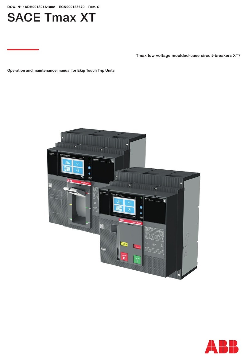
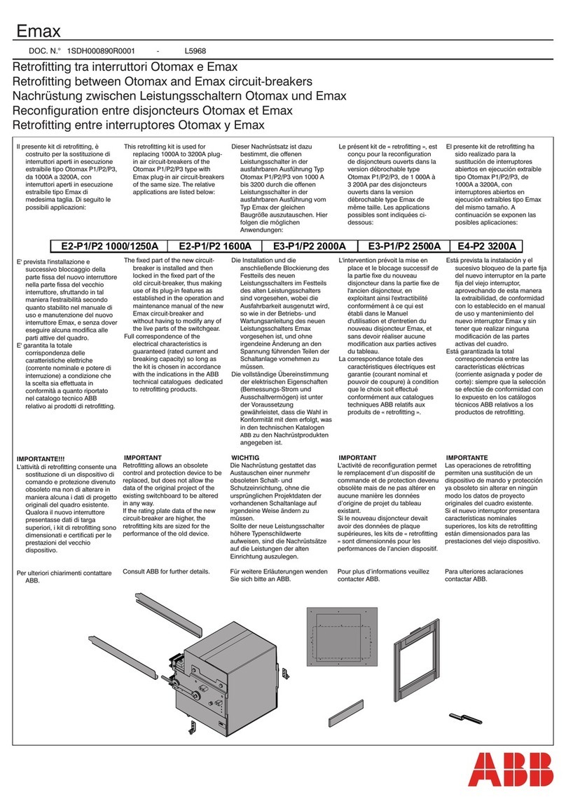
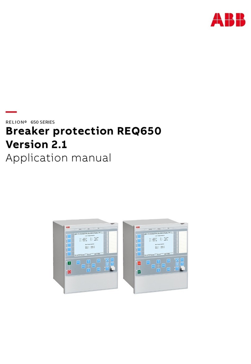
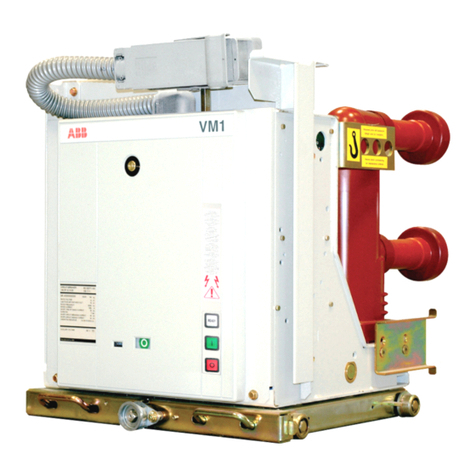
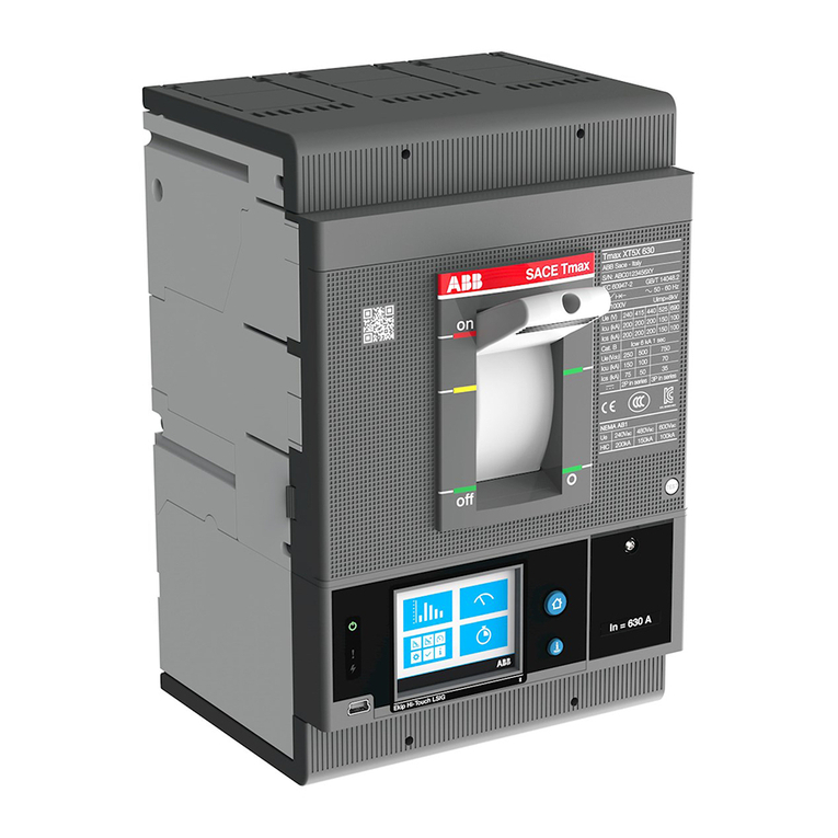
ABB XT7 User manual

Doc N.°1SDH002013A1001 - ECN000097723 - Rev. B
SACE Tmax XT7 - XT7M
Istruzioni di installazione XT7-XT7M
Installation instructions XT7-XT7M
Installationsanleitung XT7-XT7M
Instructions pour l'installation XT7-XT7M
Instrucciones de instalación XT7-XT7M
说明书XT7-XT7M
2
Usare cavi o barre isolate o eseguire prove di tipo specifiche sull' installazione.
Use cable or insulated busbars or perform specific type test on the installation.
Kabel oder isolierte Sammelschienen verwenden oder die spezifische Typprüfungauf der
Installation durchführen.
Utiliser un câble ou des barres isolées ou réalise run test de type spécifique sur installation.
Utilizar un cable o barras aisladas o efectuar una prueba de tipo específico sobre instalacíon.
使用电缆或经绝缘处理的, 否则需对进行指的型式试验
ATTENZIONE! Istruzioni relative alla Trip unit Ekip Touch sono reperibili con il documento .1SDH001821A1001
WARNING! Istructions on Ekip Touch Trip unit are available with document 1SDH001821A1002.
ACHTUNG! Anweisungen zu Trip unit Ekip Touch finden Sie mit dem Dokument 1SDH001821A1003.
ATTENTION! Istructions concernant Trip unit Ekip Touch peuvent être trouvées avec le document 1SDH001821A1004.
ATENCIÓN! Instrucciones sobre Trip unit Ekip Touch se encuentran con el documento 1SDH001821A1005.
警告!Ekip Touch脱扣器有可用的说明文件 1SDH001821A1002.
ATTENZIONE! Istruzioni relative alla manutenzione sono reperibili con il documento 1SDH002013A1002.
WARNING! Maintenance istructions are available with document 1SDH002013A1002.
ACHTUNG! Anweisungen zu Wartung finden Sie mit dem Dokument 1SDH002013A1002.
ATTENTION! Istructions concernant entretien peuvent être trouvées avec le document 1SDH002013A1002.
ATENCIÓN! Instrucciones sobre mantenimiento se encuentran con el documento 1SDH002013A1002.
告! 维护指有可用的说明件 1SDH002013A1002.

1
2
Tipologie di terminali per interruttori estraibili
Type of terminals for withdrawable breakers
Anschlusstypen für ausfahrbare Leistungsschalter
Typologies de prises pour disjoncteurs débrochables
Tipologías de terminales para interruptores extraíbles
抽式路的子类型
FG
0 mm
A
B
C
B
D
E
HR VR ES
SHR* EF FCCuAl*
2,5Nm
X
X
Y
Y
ø
140mm
5.5"
70mm
2.75"
(III) (IV)
4Nm
9.21"
(III)
EG
F
CDB
≤440V
≤690V
Ue A
>440V
IEC
UL
50
100
240 163 130 240 130 200 200
20 10 200 200 200 200
20 10 200 200 200 200
*not listed UL
≤600V

3
Tipologie di terminali per interruttori fissi
Type of terminals for fixed breakers
Anschlusstypen für feste Leistungsschalter
Typologies de prises pour disjoncteurs fixes
Tipologías de terminales para interruptores extraíbles
固式路的子类型
Sul sito web:
On the website:
Zur website:
Sue le site web:
En el sitio web:
在网上:
http://www.abb.com/abblibrary/DownloadCenter
Sono disponibili i seguenti disegni:
The following drawings are available:
Folgonden Zeichnungen sind lieferbar:
Sont disponibles es dessins suivants:
Los siguientes módulos està disponibles:
有设计图可用:
HR VR ES
FEF FCCuAl 4X240mm2 FCCuAl 2X240mm2*
*not listed UL
For fixed toggle versions:
· F
· EF
· ES
· FCCuAl
· HR-VR
For fixed stored energy versions:
· F
· EF
· ES
· FCCuAl
· HR-VR
For fixed withdrawable versions:
· HR-VR
· HR-VR
· SHR
· EF-ES
1SDH002013A1101
1SDH002013A1103
1SDH002013A1105
1SDH002013A1107
1SDH002013A1109
1SDH002013A1102
1SDH002013A1104
1SDH002013A1106
1SDH002013A1108
1SDH002013A1110
1SDH002013A1120
1SDH002013A1121
1SDH002013A1122
1SDH002013A1123

4
Max Ø 3.3 mm
Max Ø 0.13"
Max Ø 3.3 mm
Max Ø 0.13"
8 mm
0.31"
8 mm
0.31"
2
0.5÷2.5 mm
20 AWG÷14 AWG
2
0.5÷2.5 mm
20 AWG÷14 AWG
2
1
Stored energy circuit breaker operations5
Controllare che l’interruttore sia aperto (segnalatore aperto/chiuso
"O - OPEN"), e controllare che le molle siano scariche
(segnalatore molle "bianco - DISCHARGED SPRING")
Check that the circuit-breaker is open (open/closed indicator "O -
OPEN"), and check that the springs are discharged (spring
signalling device "white - DISCHARGED SPRING")
Sicherstellen, dass der Leistungsschalter ausgeschaltet ist
(Anzeige aus/ein “O - OPEN"), und prüfen, dass die Federn
entspannt sind (Federnanzeige "weiß - DISCHARGED SPRING")
Contrôler que le disjoncteur soit ouvert (indicateur ouvert/fermé
“O - OPEN"), et contrôler que les ressorts sont débandés
(indicateur ressorts "blanc - DISCHARGED SPRING")
Controlar que el interruptor esté abierto (indicador
abierto/cerrado “O - OPEN") y controlar que los resortes estén
descargados (indicador resortes "blanco - DISCHARGED
SPRING")
检路是否开 (开/闭合“O - 断开”), 检弹是否已
释压力 (弹“白色 - 弹已释压力)
Carica delle molle - Tirare la leva [A] verso il basso più volte fino a
quando il segnalatore di molle cariche [B] è "giallo - CHARGED
SPRING"
Charging the springs - Pull the lever [A] downwards several times
until the springs charged signalling device [B] is “yellow -
CHARGED SPRING”
Spannen der Federn - Den Hebel [A] mehrmals nach unten
ziehen, bis die Anzeige Federn gespannt [B] auf "gelb -
CHARGED SPRING" steht
Bandage des ressorts - Tirer le levier [A] vers le bas plusieurs fois
tant l'indicateur de ressorts bandés [B] devient "jaune -
CHARGED SPRING"
Carga de los resortes - Tirar de la palanca [A] hacia abajo varias
veces hasta que el indicador de resortes cargados [B] se ponga
amarillo - CHARGED SPRING”
加载弹 - 杆[A]向下拉多次, 直至加载弹的[B]变成“黄
色 - 弹已加载”
AB
Wiring connections

Controllare che l'interruttore sia aperto (segnalatore aperto/chiuso
“O - OPEN”), e controllare che le molle siano cariche (segnalatore
molle "giallo - CHARGED SPRING").
Check that the circuit-breaker is open (open/closed signalling
device “O - OPEN”), and check that the springs are charged
(springs signalling device “yellow - CHARGED SPRING”).
Sicherstellen, dass der Leistungsschalter ausgeschaltet ist
(Anzeige aus/ein “O - OPEN"), und prüfen, dass die Federn
gespannt sind (Federnanzeige "weiß - CHARGED SPRING").
Contrôler que le disjoncteur soit ouvert (indicateur ouvert/fermé
“O - OPEN"), et contrôler que les ressorts sont bandés (indicateur
ressorts "jaune - CHARGED SPRING").
Controlar que el interruptor esté abierto (indicador
abierto/cerrado “O - OPEN") y controlar que los resortes estén
cargados (indicador resortes "amarillo - CHARGED SPRING").
检路是否开 (开/闭合“O - 断开”), 检弹是否已
加载 (弹“黄色 - 弹已加载).
Chiusura - Premere il pulsante di chiusura "I - Push ON"
Closing - Press the closing pushbutton “I - Push ON”
Einschalten - Die Einschalttaste "I - Push ON" drücken
Fermeture - Appuyer sur le bouton de fermeture "I - Push ON"
Cierre - Apretar el pulsador de cierre "I - Push ON"
闭合 - 闭合钮“I - 按下开启”
Controllare che l'interruttore sia chiuso (segnalatore aperto/chiuso
“I - CLOSED"), e controllare che le molle siano scariche
(segnalatore molle "bianco - DISCHARGED SPRING")
Check that the circuit-breaker is closed (open/closed indicator "I -
CLOSED"), and check that the springs are discharged (spring
signalling device "white - DISCHARGED SPRING”
Sicherstellen, dass der Leistungsschalter eingeschaltet ist
(Anzeige aus/ein “I - CLOSED"), und prüfen, dass die Federn
entspannt sind (Federnanzeige "weiß - DISCHARGED SPRING")
Contrôler que le disjoncteur soit fermé (indicateur ouvert/fermé “I -
CLOSED"), et contrôler que les ressorts sont débandés (indicateur
ressorts "blanc - DISCHARGED SPRING")
Controlar que el interruptor esté cerrado (indicador
abierto/cerrado “I - CLOSED") y controlar que los resortes estén
descargados (indicador resortes "blanco - DISCHARGED
SPRING")
检路是否闭合 (开/闭合“I - 闭合”), 检弹是否已
释压力 (弹“白色 - 弹已释压力)
Push ON

6
Apertura - Premere il pulsante di apertura “O - Push OFF”
Opening - Press the opening pushbutton “O - Push OFF”
Ausschalten - Die Ausschalttaste "O - Push OFF" drücken
Fermeture - Appuyer sur le bouton d'ouverture "O - Push OFF”
Apertura - Apretar el pulsador de apertura “O - Push OFF”
开 - 开钮“O - 按下关闭”
Push OFF
Withdrawable version circuit breakers: draw in - draw out operation
Controllare che l'interruttore sia aperto (segnalatore aperto/chiuso
“O - OPEN”), e controllare che le molle siano scariche
(segnalatore molle "bianco - DISCHARGED SPRING")
Check that the circuit-breaker is open (open / closed indicator "O
- OPEN"), and check that the springs are discharged (spring
signalling device "white - DISCHARGED SPRING")
Sicherstellen, dass der Leistungsschalter ausgeschaltet ist
(Anzeige aus/ein “O - OPEN"), und prüfen, dass die Federn
entspannt sind (Federnanzeige "weiß - DISCHARGED SPRING")
Contrôler que le disjoncteur soit ouvert (indicateur ouvert/fermé
“O - OPEN"), et contrôler que les ressorts sont débandés
(indicateur ressorts "blanc - DISCHARGED SPRING")
Controlar que el interruptor esté abierto (indicador
abierto/cerrado “O - OPEN") y controlar que los resortes estén
descargados (indicador resortes "blanco - DISCHARGED
SPRING")
检路是否开 (开/闭合“O - 断开”), 检弹是否已
释压力 (弹“白色 - 弹释压力)
Verificare che il segnalatore sulla parte fissa indichi la posizione
DISCONNECT.
Make sure that signalling device on the fixed part indicates the
DISCONNECT position.
Die Anzeige auf dem festen Teil meldet nun die Position
DISCONNECT.
Vérifier que l'indicateur sur la partie fixe signale la position
DISCONNECT.
Verificar que el indicador en la parte fija señale la posición
DISCONNECT.
检认固分的是否显示“开”.

Posizionare la parte mobile nella parte fissa e spingerla sino a
quando va in arresto.
Position the moving part in the fixed part and push until it comes
to a stop.
Das bewegliche Teil im festen Teil anordnen und es schieben, bis
es anschlägt.
Placer la partie mobile dans la partie fixe et la pousser jusqu'à ce
qu'elle arrive en butée.
Poner la parte móvil en la parte fija y empujarla hasta el bloqueo.
活动分调固分的, 并向前动.
ATTENZIONE! Ruotare la targhetta di 90° prima di
inserire la parte mobile.
WARNING! Rotate the label by 90° before inserting the
mobile part.
ACHTUNG! Vor dem Einsetzen des beweglichen Teils
um 90 ° drehen Sie das Etikett.
ATTENTION! Tourner la plaque de 90° avant d'insérer la
partie mobile.
¡ATENCIÓN! Girar la placa 90° antes de insertar la parte
móvil.
注意! 插入活动部分时应转动牌子90°.
Estrarre la manovella di sezionamento dalla propria sede.
Extract the disconnection crank from its housing.
Die Trennkurbel aus ihrem Sitz herausziehen.
Extraire la manivelle de sectionnement de son logement.
Extraer de su alojamiento la manivela de seccionamiento.
摇柄.

Premere il pulsante di blocco ed inserire la manovella nella parte
mobile. In questa fase la parte mobile è ancora in posizione
DISCONNECT.
Press the lock pushbutton and insert the crank in the moving part.
In this phase the moving part is still in DISCONNECT position.
Die Verriegelungstaste drücken und die Handkurbel in das
bewegliche Teil stecken. In dieser Phase befindet sich das
bewegliche Teil noch in der Position DISCONNECT.
Appuyer sur le bouton de blocage et introduire la manivelle dans
la partie mobile. Dans cette phase la partie mobile est encore en
position DISCONNECT.
Presionar el pulsador de bloqueo e introducir la manivela en la
parte móvil. En esta fase la parte móvil está aún en posición
DISCONNECT.
锁钮, 摇柄插活动分. 在该骤, 活动分应还在“
开”.
Ruotare la manovella in senso orario sino a quando il pulsante
fuoriesce ed il segnalatore indica che l'interruttore è in posizione
TEST.
Turn the crank clockwise until the pushbutton comes out and the
indicator shows that the circuitbreaker is in TEST position.
Die Handkurbel im Uhrzeigersinn drehen, bis die Taste austritt.
Die Anzeige meldet nur die Stellung des Leistungsschalters in der
Position TEST.
Tourner la manivelle dans le sens horaire jusqu'à ce que le bouton
sorte et l'indicateur signale que le disjoncteur est en position
TEST.
Girar la manivela en sentido horario hasta que salga el pulsador y
el indicador señale que el interruptor está en posición TEST.
顺时针转动摇柄, 钮露, 且指路在“测试”.
1
Premere il pulsante di blocco dopodichè ruotare la manovella in
senso orario sino a quando il pulsante fuoriesce ed il segnalatore
indica che l'interruttore è in posizione CONNECT.
Press the lock button and then rotate the crank clockwise until the
button comes out and the indicator shows that the circuit-breaker
is in the CONNECT position.
Die Verriegelungstaste drücken und danach die Handkurbel im
Uhrzeigersinn drehen, bis die Taste austritt. Die Anzeige meldet
nun die Stellung des Leistungsschalters in der Position
CONNECT.
Appuyer sur le bouton de blocage puis tourner la manivelle dans
le sens horaire jusqu'à ce que le bouton sorte et l'indicateur
signale que le disjoncteur est en position CONNECT.
Presionar el pulsador de bloqueo y después girar la manivela en
sentido horario hasta que el pulsador salga y el indicador señale
que el interruptor está en posición CONNECT.
锁钮, 然后顺时针转动摇柄, 钮露, 且指
路在“连”.
11
2

Estrarre la manovella.
Extract the crank.
Die Handkurbel herausziehen.
Extraire la manivelle.
Extraer la manivela.
摇柄.
Riporre la manovella nella propria sede.
Replace the crank in its housing.
Die Handkurbel in ihren Ruhesitz zurückstecken.
Remettre la manivelle dans son logement.
Volver a poner la manivela en su alojamiento.
摇柄回原.
Per estrarre la parte mobile dalla parte fissa eseguire in senso
inverso le medesime operazioni indicate per l'inserzione. Dopo
l'estrazione, per rimuovere la parte mobile, sbloccare il blocco di
sicurezza.
To extract the moving part from the fixed part, perform the same
steps indicated for insertion in reverse order. After extraction, in
order to remove the moving part, unlock the safety lock.
Um das bewegliche Teil aus dem festen Teil herauszuziehen, die
gleichen Vorgänge, die zum Einfahren angegeben sind, in der
umgekehrten Reihenfolge ausführen. Nach dem Ausfahren zum
Entfernen des beweglichen Teil die Sicherheitsverriegelung
entriegeln.
Pour extraire la partie mobile de la partie fixe effectuer les mêmes
opérations indiquées pour l'embrochage
dans le sens inverse. Après le débrochage, pour enlever la partie
mobile, débloquer le verrou de sécurité.
Para extraer la parte móvil de la parte fija efectuar en sentido inverso
las mismas operaciones indicadas para la inserción. Después de la
extracción, para quitar la parte móvil, desbloquear el bloqueo de
seguridad.
为活动分从固分, 应照插的骤向执行. 后, 为
移除活动分, 应锁全锁.
11
2

7Wiring diagram - XT7M
Open/closed aux.contacts
of circuit-breaker
First opening coil
Closing coil
Second opening coil or
undervoltage coil
Ready to close contact
Signalling modules
and/or
and/or
and/or
and/or
Temperature monitoring modules
Ekip synchro check
Communication modules
Redundant communication
modules
Current sensor input on
external neutral
Zone selectivity
RC residual current protection
sensor input
Transformer star centre
sensor input
Ekip measuring voltage
sockets
Protection relay tripped
signalling contact
YP reset trip coil S51
Closing springs loading motor
Contact for signalling position
of loaded springs
ModuleModule
Auxiliary supply and Local Bus

8Wiring diagram - XT7
Open/closed aux.contacts
of circuit-breaker
First opening coil
Second opening coil or
undervoltage coil
YO2/YU opening coil state
signalling contact
Signalling modules
and/or
and/or
and/or
and/or
Temperature monitoring modules
Ekip synchro check
Communication modules
Redundant communication
modules
Auxiliary supply and Local Bus
Current sensor input on
external neutral
Zone selectivity
RC residual current protection
sensor input
Transformer star centre
sensor input
Ekip measuring voltage
sockets
Protection relay tripped
signalling contact
Auxiliar early contacts operated
by crank handle
Tripped position breaker
signalling contact
ModuleModule

9
Protezione S - Protection S - Schutzfunktion S - Protection S - Protección S -
Protezione L - Protection L - Schutzfunktion L - Protection L - Protección L -
t
Ifault
12s
1800A (3xI1)
t
t
t
t
Ifault
0,1
7500A (7,5In)
0,1s
(t=k/If2)
(t=k)
10
L保护
S保护
Ifault
Note-Notes-Anmerkungen-Nota-Notas-注释
Ifault > I1 = Alarm
Esempio-Example-Beispiel-Exemple-Ejemplo-例子
In=1000A
I1=1000 x 0,60 = 600A
t1= 12s@1800A (3xI1)
Note-Notes-Anmerkungen-
Nota-Notas- 注释
If > I2 = Alarm
Esempio-Example-Beispiel-Exemple-Ejemplo-例子
In=1000A
I2=1000 x 7,5 = 7500A
t2= 0,1s
Curva di intervento a tempo dipendente
Inverse-time trip curve
Auslösekennlinie für stromabhängige
Verzögerung
Courbe de déclenchement à temps inverse
Curva de actuación de tiempo dependiente
固时间的干预曲线
Curva di intervento a tempo fisso
Fixed-time trip curve
Auslösekennlinie für stromunabhängige
Verzögerung
Courbe de déclenchement à temps fixe
Curva de actuación de tiempo fijo
固时间的干预曲线
7500A (7,5In)

11
Protezione G - Protection G - Schutzfunktion G - Protection G - Protección G -
Protezione I - Protection I - Schutzfunktion I - Protection I - Protección I -
t
Ifault
I
t
I
t
t=k
t=k/I2
11
I保护
G 保护
Esempio - Example - Beispiel - Exemple - Ejemplo - 例子
In=1000A
I3=1000 x 7,5 = 7500A
Esempio - Example - Beispiel - Exemple - 例子
In=1000A
I4=1000 x 0,6 = 600A
t4= 0,4s@1344A (2,24xI4)
Note - Notes - Anmerkungen - Nota -
Notas - 注释
If > I4 = Alarm
Note-Notes-Anmerkungen-Nota-Notas-注释
Ifault > I3 = Alarm

12 Tabella riassuntiva segnalazioni LED
HELP
13
Alcune segnalazioni led rilevano errori di connessione o funzionamento che richiedono operazioni correttive o di manutenzione.
Qui di seguito i suggerimenti di controllo riferiti alla tabella led precedente:
Nota HELP Operazione
A Contattare ABB dettagliando lo stato dei led su unità.
BVerificare connessioni tra sganciatore e accessori (Rating Plug, trip coil, sensori, ecc...)
C Normale funzionamento, segnalazione prevista dallo sganciatore
D
Errore di impostazione dei dip-switch: verificare e correggere le seguenti condizioni:
• Tutti i dip-switch sono in posizione on.
• I1 ≥ I2 or I2 ≥I3.
• Iu < (2 ∙ In ∙ I1) nel caso InN = 200 %.
• I4 < 0.3 In (con In = 100 A), 0.25 In (con In = 400 A) o 0.2 In (per tutte le altre taglie), in assenza di alimentazione ausiliaria.
• t2 > 0.4s (nel caso di interruttore UL)
• t4 > 0.4s (nel caso di interruttore UL)
• I4 > 1200 A (nel caso di interruttore UL)
E Eseguire installazione.
F Connettersi con Ekip Connect per impostare il Local Bus o confermare la manutenzione.
G Contattare ABB per ripristino compatibilità software tra Ekip Dip e Mainboard.
H Sostituire batteria.
Lampeggio lento
(0.5Hz) Lampeggio veloce Accesi fissi 2 lamp.
ogni 2 s
3
lamp.
ogni
3 s
4
lamp.
ogni
4 s HELP
Colore e LED Tutti R G Tutti
R+G Tutti R R
(singolo) G Tutti R R
(singolo) G Tutti R GG G
Errore configurazione interna
(5) x A
Trip coil disconnessa o
comando di apertura fallito
x B
Sensori di corrente sconnessi
xB
Errore Rating Plug
XB+E
Temporizzazione di protezione
x C
Preallarme L
x C
Trip (2)
x C
Hardware Trip (3)
x x B
Errore di installazione
x E
Errore di parametri
x D
Stato interruttore non
definito o in errore
x B
Errore su Local Bus
x F
Allarme manutenzione
x F
Incompatibilità Software
x x G
Batteria scarica (durante
autotest)
(4)(1)
x H
Legenda colori led
Nella tabella sopra sono riportati i colori dei led, da interpretare come segue:
•
R = led rosso (led di allarme L, S, I, G).
•
G = led giallo (led di preallarme L)
(1)
(1)
(1)
(1)
ACalibrazione in corso
x
Qui di seguito la tabella riepilogativa delle segnalazioni disponibili con i led di protezione, e delle operazioni da seguire in riferimento ad allarmi o
condizioni anomale segnalate.
(1) Non disponibile per relé Ekip DIP: LS/I, LIG, M-I, G-LS/I.
(2) L’ultimo trip può essere visualizzato anche con sganciatore spento, premendo il tasto iTest.
(3) L’Hardware Trip è segnalato con l’accensione del led giallo di preallarme L e rosso di protezione I.
(4) Cinque lampeggi quando avviato autotest.
(5) Errore presente con una tra le tre opzioni di lampeggio proposte a fianco.
Tipo di informazione
(2Hz)

14 Summary table of LED signals
HELP
15
Some LED signals indicate connection errors or operational errors that require corrective or maintenance
operations. The following are the suggestions for checking with reference to the preceding LED table:
HELP note Operation
A Contact ABB and give details about the state of the LEDs on the unit.
BCheck the connections between trip unit and accessories (Rating Plug, trip coil,
sensors, etc).
C Normal operation/signalling provided by the trip unit.
D
Error in setting of the dip-switches. Check and correct the following conditions:
• All the dip-switches of L are in the ON position
• I1 ≥ I2 or I2 ≥I3.
• Iu < (2 ∙ In ∙ I1) in the case where InN = 200 %.
• I4 < 0.3 In (with In = 100 A), 0.25 In (with In = 400 A) or 0.2 In (for all other sizes), in the absence of auxiliary power supply.
• t2 > 0.4s (in the case of UL circuit-breaker)
• t4 > 0.4s (in the case of UL circuit-breaker)
• I4 > 1200 A (in case of UL circuit-breaker)
E Carry out installation.
F Connect via Ekip Connect in order to set the Local Bus or to conrm maintenance.
G Contact ABB to restore software compatibility between Ekip Dip and Mainboard.
H Replace the battery.
Slow flashing
(0.5Hz) Fast flashing (2 Hz) On and fixed 2 flashes
every 2 s
3
flashes
every
3 s
4
flashes
every
4 s HELP
Colour and LED All R Y All
R+Y All R R
(single) Y All R R
(single) Y All R YY Y
Internal conguration error (5) x A
Trip coil disconnected or
trip command failed
x B
Current sensors disconnected
xB
Rating Plug error
XB+E
Protection delay
x C
Pre-alarm L
x C
Trip (2)
x C
Hardware Trip (3)
x x B
Installation error
x E
Parameter error
x D
Circuit-breaker state not
dened or in error
x B
Error on Local Bus
x F
Maintenance alarm
x F
Software incompatibility
x x G
Low battery (during self-
test)
(4)(1)
x H
Key to LED colours
The above table lists the colors of the LEDs, to be interpreted as follows:
•
R = red LED (alarm LED L, S, I, G).
•
Y = yellow LED (pre-alarm LED L).
(1)
(1)
(1)
(1)
ACalibration in progress
x
The following table summarises the signals available with the protection LEDs and the operations to be carried out in response to alarms or fault
conditions signalled
(1) Not available for Ekip DIP relay: LS/I, LIG, M-I, G-LS/I.
(2) The last trip can also be displayed with trip unit off, by pressing the iTest key.
(3) The Hardware Trip is signalled by lighting of the pre-alarm L yellow LED and the protection I red led.
(4) Five flashes when self-test is started up.
(5) Error present with one of the three flashing options displayed alongside.
Type of information

16 Übersichtstabelle der LED-Meldungen
HELP
17
Einige Led-Meldungen erfassen Anschluss-oder Betriebsfehler, die Korrekturmaßnahmen oder Instandhaltung verlangen.
Hier folgen die Empfehlungen zur Kontrolle, die sich auf die vorherige Led-Tabelle behiezen:
Anm. HELP Vorgang
A Kontakt mit ABB aufnehmen und den Zustand der Leds auf der Einheit angeben.
BAnschlüsse zwischen Auslöser und Zubehör prüfen (Rating Plug, Auslösespule,
Sensoren, etc).
C Normaler Betrieb/Meldungen, die vom Auslöser vorgesehen sind.
D
Einstellfehler der Dip-Schalter. Die folgenden Bedingungen prüfen und ausbessern:
• Alle Dip-Switches von L stehen in Position On
• I1 ≥ I2 oder I2 ≥ I3..
• Iu < (2 ∙ In ∙ I1) im Fall von InN = 200 %.
• I4 < 0.3 In (mit In = 100 A), 0.25 In (mit In = 400 A) oder 0.2 In (für alle anderen Baugrößen), wenn keine Hilfsstromversorgung vorhanden ist.
• t2 > 0.4s (im Fall von Leistungsschalter UL)
• t4 > 0.4s (im Fall von Leistungsschalter UL)
• I4 > 1200 A (im Fall von Leistungsschalter UL)
E Installation ausführen.
F An Ekip Connect anschließen, um den Lokaler Bus einzustellen oder die Wartung zu bestätigen.
G Kontakt mit ABB aufnehmen, um die Veträglichkeit der Software zwischen Ekip Dip und Mainboard wieder herzustellen.
H Batterie austauschen.
Langsames Blinken
(0.5 Hz)
Schnelles Blinken Dauernd an 2 Blinkv.
alle 2 s
3
Blinkv.
alle
3 s
4
Blinkv
alle
4 s HELP
Farbe und Led Alle R G Alle
R+G Alle R R
(einzeln) G All R R
(einzeln) G Alle R GG G
Fehler der internen Konfiguration (5) x A
Tripspule nicht angeschlossen
oder Tripbefehl missulngern
x B
Stromsensoren abgetrennt
xB
Fehler Bernessungsstrommodul
XB+E
Verz gerung Schutzfunktionö
x C
Pre-alarm L
x C
Trip (2)
x C
Hardware auslösen (3)
x x B
Installationsfehler
x E
Parameterfehler
x D
Zustand Leistungsschalter nicht
festgelegt oder falsch
x B
Fehler auf Lokaler Bus
x F
Instandhaltungsalarm
x F
Unverträglichkeit der Software
x x G
Batterie leer (während
Eigentest)
(4)(1)
x H
Legende der LED-Farben
In der obigen Tabelle stehen die Farben der LEDs, die wie folgt zu deuten sind:
•
R = rote LED (alarm-led L, S, I, G).
•
G = gelbe LED (Voralarm-led L).
(1)
(1)
(1)
(1)
AKalibrierung läuft
x
Hier folgt die Ubersichtstabelle der Meldungen, die mit den Leds der Schutzfunktionen verfugbar sind, und der Vorgange, die im Bezug auf
gemeldete Alarme oder Storsituationen zu befolgen sind.
(1) Nicht verfügbar für Ekip DIP-relais: LS/I, LIG, M-I, G-LS/I.
(2) Die letzten Auslösung kann auch mit ausgeschaltetem Auslöser angezeigt werden, wenn man die iTest-Taste drückt.
(3) Der Hardware auslösen wird durch das Aufleuchten der gelben voralarm-led L und der roten Schutz-led I gemeldet.
(4) Fünf Blinkvorgänge, wenn der Eigentest gestartet ist.
(5) Fehler vorhanden mit einer der drei Blinkoptionen, die hier neben vorgeschlagen werden.
Art der Information (2 Hz)

18 Tableau récapitulatif des voyants de signalisation
HELP
19
Certains voyants de signalisations révèlent des erreurs de connexion ou de fonctionnement exigeant des opérations de correction ou
de maintenance. Voir ci-dessous les suggestions de contrôle se référant au tableau voyants précédent:
Remarque HELP Vorgang
A Contactez ABB en détaillant l’état des voyants sur l’unité.
BVérifier les connexions entre déclencheur et accessoires (Rating Plug, trip coil,
capteurs, etc).
C Fonctionnement normal, signalisation prévue par le déclencheur.
D
Erreur de réglage des commutateurs dip. Verifier et corriger les conditions suivantes:
• Tous les dips de L sont en position on
• I1 ≥ I2 ou I2 ≥ I3..
• Iu < (2 ∙ In ∙ I1) en cas de InN = 200 %.
• I4 < 0.3 In (avec In = 100 A), 0.25 In (avec In = 400 A) ou 0.2 In (pour toutes les autres tailles), en l’absence d’alimentation auxiliaire.
• t2 > 0.4s (en cas de disjoncteur UL)
• t4 > 0.4s (en cas de disjoncteur UL)
• I4 > 1200 A (en cas de disjoncteur UL)
E Exécuter l’installation.
F Se connecter avec Ekip Connect pour configurer le Local Bus ou confirmer la maintenance.
GContacter ABB pour rétablir la compatibilité logicielle entre Ekip Dip et Carte Mère.
H Remplacer la batterie.
Clignotement lent
(0.5 Hz)
Clignotement rapide Accesoires fixes 2 clign.
toutes les 2 s
3
clign.
toutes
les 3 s
4
clign.
toutes
les 4 s HELP
Couleur et voyant Tous R J Tous
R+J Tous R R
(simple) J Tous R R
(simple) JTous R JJ J
Erreur configuration interne
(5) x A
Trip coil déconnecté ou command
de déclenchement échouée
x B
Capteurs de courant déconnectés
xB
Erreur Rating Plug
XB+E
Temporisation de protection
x C
Pré-alarm L
x C
Trip (2)
x C
Hardware Trip
(3)
x x B
Erreur d’Installation
x E
Erreur de paramètres
x D
Etat disjoncteur non défini ou en
erreur
x B
Erreur sur Local Bus
x F
Alarme maintenance
x F
Incompatibilité logicielle
x x G
Batterie déchargée (pendant
autotest) (4)(1)
x H
Légende couleurs voyants
Le tableau ci-dessous reporte les couleurs des voyants, à interpréter de la manière suivante:
•
R =voyant rouge (voyant d’alarme L, S, I, G).
•
J = voyant jaune (voyant de pré-alarme L).
(6)
(1)
(1)
(1)
ACalibration en cours
x
Voir ci-dessous le tableau recapitulatif des signalisations disponibles avec les voyants de protection, et des operations a suivre
par reference aux alarmes ou aux conditions anormales signalees.
(1) Non disponible pour le relais Ekip DIP: LS/I, LIG, M-I, G-LS/I.
(2) Le dernier déclenchement est visualisé même avec déclencheur éteint, en appuyant sur la touche iTest.
(3) L'Hardware Trip est signalé par allumage du voyant jaune de pré-alarme L et rouge de protection I.
(4) Cinq clignotements quand l'autotest a démarré.
(5) Erreur présente avec une des trois options de clignotement proposées ci-contre.
Type d’information (2 Hz)

20 Tabla de resumen señalizaciones leds
HELP
21
Algunas señalizaciones leds evidencian errores de conexión o funcionamento que requieren operaciones correctivas o de
mantenimiento. A continuación las sugerencias de control referidas a la tabla led de arriba:
Nota HELP Operación
A Ponerse en contacto con ABB detallando el estado de los leds en la unidad
BVerificar las conexiones entre el relé y los accesorios (Rating Plug), solenoide de apertura,
sensores, etc).
C Funcionamiento normal, señalización prevista en el relé.
D
Error de configuración de los dip-switches. Verificar y corregir las siguientes condiciones:
• Todos los dip-switches de L están en posición on
• I1 ≥ I2 o I2 ≥ I3..
• Iu < (2 ∙ In ∙ I1) en el caso InN = 200 %.
• I4 < 0.3 In (con In = 100 A), 0.25 In (con In = 400 A) o 0.2 In (para todos los otros tamaños), en ausencia de alimentación auxiliar.
• t2 > 0.4s (en el caso de interruptor UL)
• t4 > 0.4s (en el caso de interruptor UL)
• I4 > 1200 A (en el caso de interruptor UL)
E Efectuar instalación.
F Conectarse con Ekip Connect para configurar el Bus Local o confirmar el mantenimiento.
G Contactar ABB para restablecer la compatibilidad software entre Ekip Dip y Mainboard.
H Sustituir la batería.
Parpadeo lento
(0.5 Hz)
Parpadeo veloz Encendidos fijos 2 parp.
cada 2 s
3
parp.
cada
3 s
4
parp.
cada
cada 4 s HELP
Color y led Todos R A Todos
R+A Todos R R
(individual) A Todos R R
(individual) ATodos R A A A
Error configuración Interna (5) x A
Solenoide de apertura desconectado
o mando de disparo malogrado
x B
Sensores de corriente desconectados
xB
Erreur Rating Plug
XB+E
Temporización de protección
x C
Prealarma L
x C
Trip (2)
x C
Hardware Trip
(3)
x x B
Error de installación
x E
Erreur de parámetros
x D
Estado interruptor no definido
o en error
x B
Error en Bus Local
x F
Alarma mantenimiento
x F
Incompatibilidad Software
x x G
Batería descargada (durante
autotest) (4)(1)
x H
Notas colores leds
En la tabla de aquí arriba se exponen los colores de los leds, que se deberán interpretar del siguiente modo:
•
R =led rojo (led de alarma L, S, I, G).
•
A = led amarillo (led de prealarma L).
(1)
(1)
(1)
(1)
ACalibración en progreso
x
A continuacion se expone la tabla de resumen de las senalizaciones disponibles con los leds de proteccion y de las operaciones
a seguir en caso de alarmas o condiciones anomalas senaladas.
(1) No disponible para el rele Ekip DIP: LS/I, LIG, M-I, G-LS/I.
(2) El último disparo puede verse incluso con el relé apagado, pulsando la tecla iTest.
(3) El Hardware Trip se señala con el encendido del led amarillo de prealarma L y rojo de protección I.
(4) Cinco parpadeos cuando se inicia el autotest.
(5) Error presente con una entre las tres opciones de parpadeo propuestas aquí al lado.
Tipo de Informatión (2 Hz)

22 LED灯报汇总
HELP
23
某些LED灯用于通知连或操作错误, 需要予纠正或维护. 是前面LED中提的检议:
注 HELP 操作
A联ABB司, 提供单元上的LED状态详情.
B检脱扣和配件 (额插头, 脱扣线, 传感, 等) 间的连.
C正常运行, 脱扣预计的通知
D
DIP开关设置错误, 检并更正以下条件:
• 有DIP开关都设在“开”.
• I1 ≥ I2 或 I2 ≥I3.
• InN = 200 %的情况下, Iu < (2 ∙ In ∙ I1).
• I4 < 0.3 In (In = 100 A), 0.25 In (In = 400 A) 或 0.2 In (对于所有其他型号), 在没有辅助电源的情况下.
• t2 > 0.4s (在UL开关情况下).
• t4 > 0.4s (在UL开关情况下).
• I4 > 1200 A (在UL开关情况下).
E执行.
F连Ekip Connect, 设本地总线, 或认维护.
G联ABB司, 复Ekip Dip和主间的软件兼性.
H更换电池.
慢速闪烁 (0.5 Hz) 快速闪烁 (2Hz) 长 2闪烁2次
3
闪
烁3次HELP
颜色和LED灯 有 R Y有
R+Y 有 R R
( )单个 Y有 R R
( )单个 Y有 R YY Y
配错误
(5) x A
脱扣线开或开启指失败
x B
电传感开
xB
额插头错误
XB+E
保护时
x C
预L
x C
脱扣 (2)
x C
硬件脱扣 (3)
x x B
错误
x E
错误
x D
路状态未义或错
x B
本地总线错
x F
维护报
x F
软件不兼
x x G
电池电量 (在自测期间) (4)(6)
x H
LED灯颜色图例
上中显示的LED灯颜色义如:
•
R = 红色LED (L, S, I, G报警LED灯).
•
Y = 黄色LED (L预警LED灯).
(6)
(6)
(6)
(6)
A
正在
x
面是保护LED可用报的汇总, 在发生报或常情况时应的操作.
(1) 对于继电Ekip DIP不可用: LS/I, LIG, M-I, G-LS/I.
(2) 也可在脱扣器关闭的情况, 钮iTest看后一次脱扣.
(3) 预黄色LED灯和保护I的红色LED灯点亮表示硬件脱扣.
(4) 启动自动测试时闪烁五次.
(5) 出现边显示的三个闪烁选项一的错误.
息类型
4
闪
烁4次
Copyright 2018-2019 ABB. All rights reserved
www.abb.com
Other manuals for XT7
1
This manual suits for next models
1
Table of contents
Other ABB Circuit Breaker manuals

ABB
ABB T7-T7M-X1 User guide

ABB
ABB HPA 12kV Guide

ABB
ABB 5VHK 250 Installation and operating instructions

ABB
ABB Tmax RC221 User manual

ABB
ABB Emax 2 IEC 60947 User manual

ABB
ABB S4 User manual

ABB
ABB HD4/R Quick guide

ABB
ABB SACE Tmax XT5 User manual

ABB
ABB SACE Tmax XT User manual

ABB
ABB Mechanism HMB-8 User manual

ABB
ABB VM1 User manual

ABB
ABB SACE Emax 2 E2.2 User manual

ABB
ABB Emax X1 B/E 1150 V User manual

ABB
ABB GE Power Break II User manual
ABB
ABB ReliaMod RMS212522LRLR User manual

ABB
ABB S800U User manual

ABB
ABB SACE Emax E1 User manual

ABB
ABB CP3200 User manual

ABB
ABB SACE Tmax T4 User manual

ABB
ABB SACE Emax 2 User manual