Micro
VersaTrip
Plus
and
Micro
Versa
Trip
PM
TrijjUnte
List
o
f
Tables
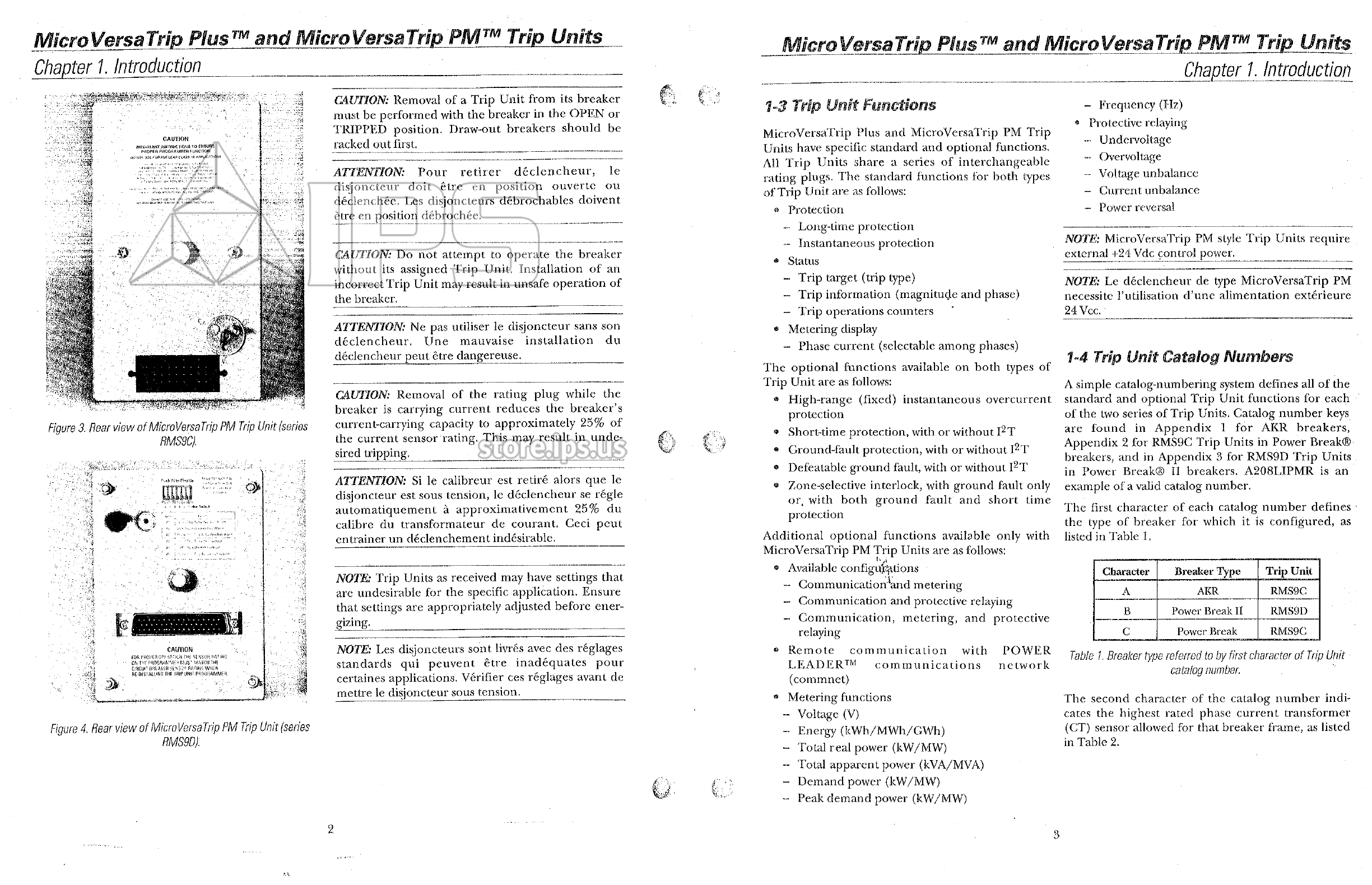
MicroVersaTrip
Plus
and
MicroVersaTrip
PM
Trip
Units
Chapter
1
.
Introduction
ft
/
Pr
3
1
.
Breaker
type
r
eferred
to
by
first
character
of
Trip
Unit
catalog
number
.
2
.
Breaker
frame
size
maximum
CT
referred
to
by
second
character
of
Trip
Unit
catalog
number
.
3
.
Installed
breaker
CT
size
referred
to
by
third
and
fourth
characters
of
Trip
Unit
catalog
number
.
4
.
Trip
Unit
catalog
number
suffixes
for
optional
functions
.
.
5
.
MicroVersaTrip
PM
Trip
Unit
suffixes
for
communication
,
metering
,
and
relaying
6
.
Rating
plug
catalog
numbers
.
7
.
Protective
relay
and
metering
accuracies
and
resolutions
.
8
.
Trip
-
time
curves
for
breaker
types
covered
in
this
guide
.
9
.
Abbreviations
used
in
setup
procedure
descriptions
.
10
.
Actions
of
function
keys
in
Trip
Unit
operating
modes
.
11
.
Lower
-
limit
delays
for
long
-
time
delay
bands
.
12
.
Lower
-
limit
delays
for
I
^
T
OUT
short
-
time
delay
bands
.
13
.
Ground
-
fault
pickup
settings
,
as
a
function
of
sensor
rating
.
..
14
.
Lower
-
limit
delays
for
ground
-
fault
delay
bands
.
15
.
Trip
Unit
rating
plug
options
.
16
.
Accessory
configuration
switch
settings
,
including
factory
defaults
.
.
17
.
Trip
Unit
display
targets
for
protective
relays
.
A
7
-
1
Read
This
First
**
.
4
)
-
The
MicroVersaTrip
Plus
and
MicroVersaTrip
PM
Trip
Units
described
in
this
publication
are
used
on
Power
Break
®
and
Power
Break
®
II
insulated
-
case
circuit
breakers
,
Type
AKR
low
-
voltage
power
circuit
breakers
,
R
-
Frame
rnolded
-
case
circuit
breakers
,
and
low
-
voltage
power
circuit
breaker
conversion
kits
.
Spectra
RMSm
molded
-
case
circuit
breakers
use
different
versions
of
MicroVersaTrip
Plus
and
MicroVersaTrip
PM
Trip
Units
that
are
not
interchangeable
with
the
units
described
here
.
Refer
to
GEH
-
5934
for
information
on
these
Trip
Units
.
4
mmmmm
:
.
s
•
:
l
4
v
.
4
4
4
5
9
ffPE
Tmmmm
a
isfifi
If
i
?
.
W
*
'
3000
A
su
t
9
10
:
•
v
.
-
f
-
ll
AW
ir
*
gm
\
:
St
i
(
§
)
v
-
r
(
GEEftctriwI
Distribution
&
Control
r
&
v
#
te
,
cr
!
?
..
:
„
16
i
'
.
HtttHtmtmiHiiiimmtMHMtHm
.
iimmHHitxtmtHtm
.
xomimHtHUMXimtHxiMi
17
1
-
2
Product
Structure
19
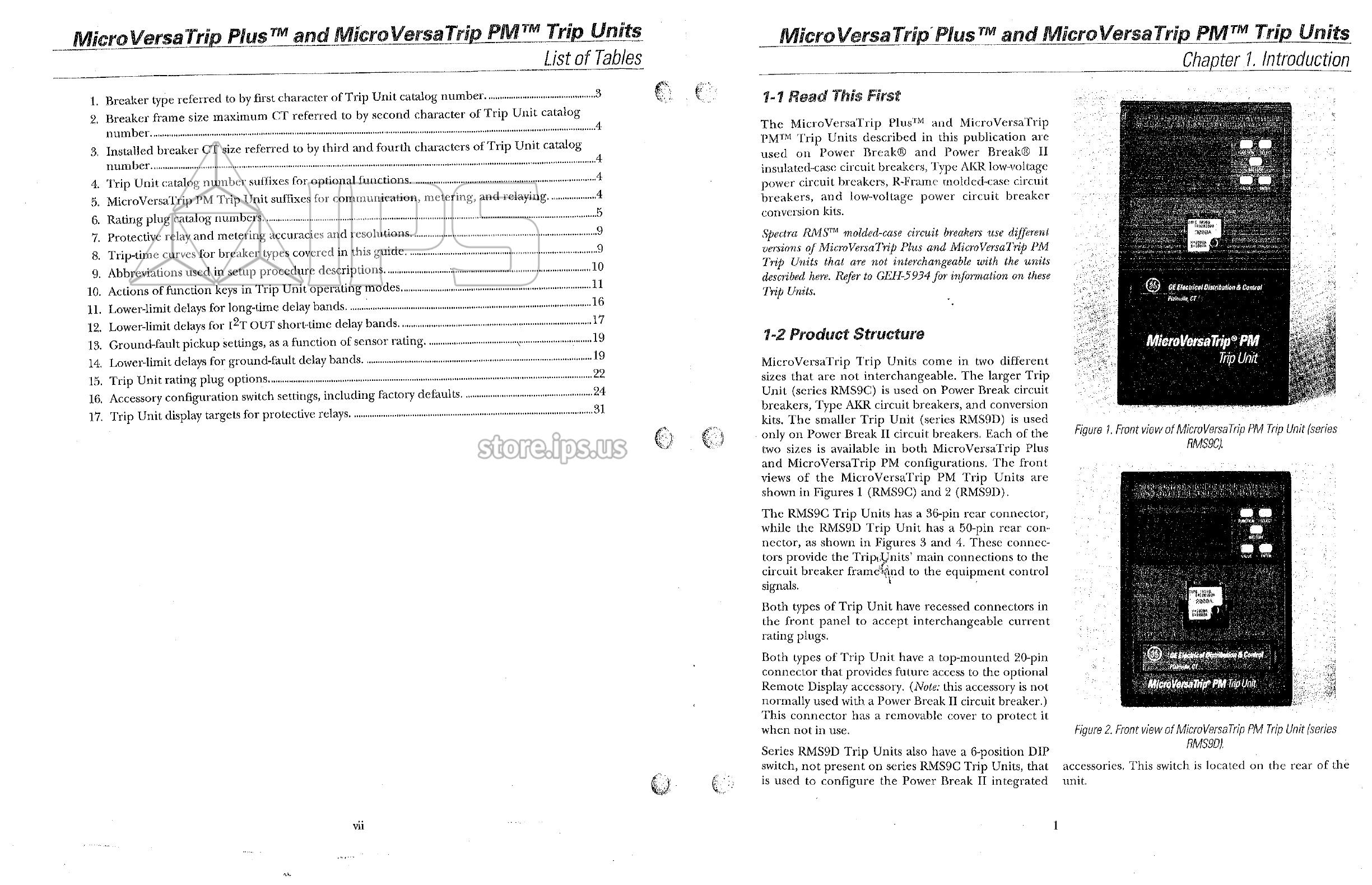
MicroVersaTrip
?
PM
19
»
MicroVersaTrip
Trip
Units
come
in
two
different
sizes
that
are
not
interchangeable
.
The
larger
Trip
Unit
(
series
RMS
9
C
)
is
used
on
Power
Break
circuit
breakers
,
Type
AKR
circuit
breakers
,
and
conversion
kits
.
The
smaller
Trip
Unit
(
series
RMS
9
D
)
is
used
only
on
Power
Break
II
circuit
breakers
.
Each
of
the
two
sizes
is
available
in
both
MicroVersaTrip
Plus
and
MicroVersaTrip
PM
configurations
.
The
front
views
of
the
MicroVersaTrip
PM
Trip
Units
shown
in
Figures
1
(
RMS
9
C
)
and
2
(
RMS
9
D
)
.
»
>
•
.
.
22
;
MHmtlUMmmoiMMMMOfJHMMMMlMIHOOmotMMMOMnMMMMtMMMMtUMHHMMIIMmMtMMMHHlUIMtMUM
»
•
>
|
I
<
M
;
.
;
=
V
V
•
V
"
,
24
•
:
:
•
.
/
;
<
.
r
31
MlMlfMMUniMlhlMtMIHHmmiMHItMHnuMHMtMtMIHOMOMtHMtimrMtlMHOHtiMMt
.
*
y
-
T
‘
I
!
W
Figure
l
Front
view
of
MicroVersaTrip
PM
Trip
Unit
(
series
RMS
9
C
)
.
i
-
are
;
'
iS
*
sssiaisii
#
*
K
:
•
•
v
•
*
•
I
-
t
The
RMS
9
C
Trip
Units
has
a
36
-
pin
rear
connector
,
while
the
RMS
9
D
Trip
Unit
has
a
50
-
pin
nector
,
as
shown
in
Figures
3
and
4
.
These
tors
•
#
4
•
i
*
.
•
.
rear
con
-
connec
-
ipiUnits
’
main
connections
to
the
circuit
breaker
framefend
to
the
equipment
control
signals
.
*
;
.
,
I
•
>
r
-
..
.
T
'
v
'
•
•
‘
viiur
ftfn
*
,
5
•
?
,
f
'
!
‘
ISP
1
'
:
§
;
1
F
'
1
‘
-
y
.
,
t
..
.
*
d
mMBmmSKI
-
-
1
'
:
r
-
Both
types
of
Trip
Unit
have
recessed
connectors
in
the
front
panel
to
accept
interchangeable
current
rating
plugs
.
Both
types
of
Trip
Unit
have
a
top
-
mounted
20
-
pin
connector
that
provides
future
access
to
the
optional
Remote
Display
accessory
.
(
Note
:
this
accessory
is
not
normally
used
with
a
Power
Break
II
circuit
breaker
.
)
This
connector
has
a
removable
cover
to
protect
it
when
not
in
use
.
Series
RMS
9
D
Trip
Units
also
have
a
6
-
position
DIP
switch
,
not
present
on
series
RMS
9
C
Trip
Units
,
that
is
used
to
configure
the
Power
Break
II
integrated
-
.
-
"
I
f
®
*
.
•.•
;
.
-
wi
i
,
:
.
m
SsVl
3
-
f
•
*
.
•
u
-
y
^
fomrsaThfPMTnpm
-
,
;
*
Figure
2
.
Front
view
of
MicroVersaTrip
PM
Trip
Unit
(
series
RMS
9
D
)
.
accessories
,
This
switch
is
located
on
the
rear
of
the
unit
,
©
C
T
-
v
i
*
VU
1