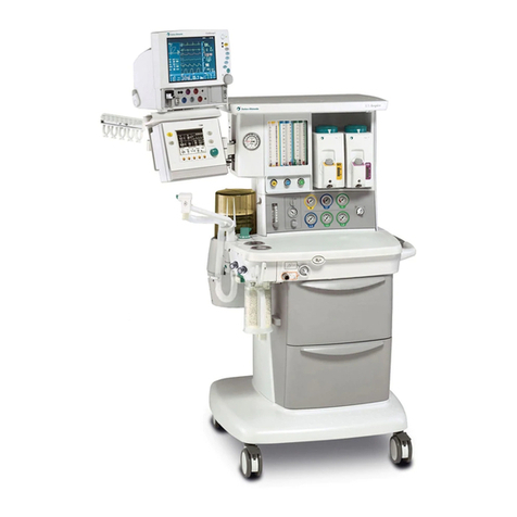
GE auisys cs2 Assembly instructions

Aisys CS²
User's Reference Manual
Software Revision 10.X

User responsibility
Datex-Ohmeda, Inc. a General Electric Company, doing business as
GE Healthcare.
This product will perform in conformity with the description thereof
contained in this User’s Reference manual and accompanying labels
and/or inserts, when assembled, operated, maintained, and repaired
in accordance with the instruction provided. This Product must be
checked periodically. A defective Product should not be used. Parts
that are broken, missing, plainly worn, distorted, or contaminated
should be replaced immediately. Should repair or replacement
become necessary, Datex-Ohmeda recommends that a telephonic or
written request for service advice be made to the nearest Datex-
Ohmeda Customer Service Center. This Product or any of its parts
should not be repaired other than in accordance with written
instructions provided by Datex-Ohmeda and by Datex-Ohmeda
trained personnel. The Product must not be altered without the prior
written approval of Datex-Ohmeda. The user of this Product shall
have the sole responsibility for any malfunction which results from
improper use, faulty maintenance, improper repair, damage, or
alteration by anyone other than Datex-Ohmeda.
U.S. Federal law restricts this device to sale by or on the
order of a licensed medical practitioner.Outside the
U.S.A., check the local laws for any restriction that may
apply.
CAUTION

Table of Contents
1 Introduction
Intended use .....................................1-2
Indications for use ..............................1-2
General information .............................1-2
Serial numbers .................................1-4
Trademarks ...................................1-5
Symbols used in the manual or on the equipment ........1-6
Symbols used on the equipment ...................1-6
Symbols used on the user interface ................1-9
Typeface conventions used ........................ 1-10
Abbreviations ....................................1-11
System information ...............................1-14
System classification ...........................1-14
Device standards IEC 60601-1:2005 .............. 1-14
Device standards IEC 60601-1:1988 .............. 1-14
Integral system components .....................1-15
Not integral system components ..................1-15
System accessories ............................1-15
System safety ................................... 1-16
Preparing for use ..............................1-16
Inspecting the system ..........................1-17
Electrical safety ...............................1-18
2 System controls and menus
System overview ..................................2-2
Using the brake ................................2-4
Using the O2 flush button ........................2-4
Positioning the display ...........................2-4
Advanced breathing system components ...............2-6
Using the bag support arm .......................2-7
2067226-001 i

Aladin cassette controls ............................ 2-8
Display controls ...................................2-9
Touch points ................................. 2-10
Measured value touch points .................... 2-10
Active alarm touch points ....................... 2-11
Anesthesia system display .........................2-12
Digit fields ................................... 2-13
Waveform fields ...............................2-13
Split screen field .............................. 2-13
Display navigation ................................2-15
Using menus .................................2-15
Using the ComWheel .......................... 2-16
Using quick keys ..............................2-16
3 Operation
System operation safety ............................3-2
Turning on the system ..............................3-3
Start a case ......................................3-4
Minimum Alveolar Concentration .................. 3-4
Starting a case using default settings ...............3-5
Starting a case using custom settings .............. 3-5
End a case ....................................3-6
Turning off the system ..............................3-7
Ventilator setup ...................................3-8
Changing ventilator mode ........................3-8
Changing ventilator settings ......................3-8
Optional ventilator procedures .................... 3-8
Auto limits ....................................... 3-9
Setting auto limits .............................. 3-9
Gas setup ...................................... 3-10
Changing gas settings ..........................3-10
Changing balance gas ..........................3-10
Changing circuit type ...........................3-10
Aisys CS²
ii 2067226-001

System setup ....................................3-13
Patient demographics ..........................3-13
Screen setup menu ............................3-13
Fresh gas usage ..............................3-16
Alarm setup .....................................3-17
Setting CO2 alarms ............................3-17
Setting MV TV alarms ..........................3-18
Setting alarm limits ............................ 3-18
Viewing alarm history .......................... 3-19
Setting alarm volume ...........................3-19
Setting apnea delay ............................3-19
Silencing leak audio alarms ..................... 3-19
Setting auto MV limits ..........................3-20
Setting to default limits ......................... 3-20
Alarms On Off ...................................3-21
Disable alarm limits ............................3-21
Next page ...................................... 3-22
Trends .........................................3-23
Setting trends ................................ 3-23
Spirometry ......................................3-24
Setting loop type ..............................3-24
Setting loop graph scaling .......................3-25
Setting patient and sensor type ...................3-25
Setting the data source .........................3-25
Setting spirometry volume type ...................3-26
Saving, viewing, and deleting spirometry loops ......3-26
Procedures ..................................... 3-27
Pause gas flow ............................... 3-27
Cardiac bypass ...............................3-27
Vital capacity .................................3-28
Cycling ......................................3-29
Timer function ...................................3-31
Using the timer ............................... 3-31
ecoFLOW .......................................3-32
Table of Contents
2067226-001 iii
Using ecoFLOW .............................. 3-33
Alternate O2 control ...............................3-34
Using Alternate O2 control ...................... 3-34
EZchange canister mode .......................... 3-36
Using EZchange canister mode ..................3-37
Condenser ......................................3-38
Draining the condenser .........................3-38
Auxiliary Common Gas Outlet .......................3-40
Using the ACGO ..............................3-40
4 Preoperative checkout
Every day before your first patient .................... 4-2
Before every patient ............................... 4-3
5 Preoperative tests
Aladin cassette installation ..........................5-2
Flow and pressure calibration ........................5-3
Circuit compliance compensation .....................5-4
Checkout menu ...................................5-5
Full test ......................................... 5-6
Vent and gas ..................................5-6
Circuit leak ....................................5-6
Circuit O2 cell ................................. 5-7
External gas monitor ............................5-7
Individual tests ....................................5-8
Vent and gas ..................................5-8
Circuit leak ....................................5-8
Circuit O2 cell ................................. 5-8
Low P leak ....................................5-8
Low P leak (machines with ACGO) .................5-9
Agent delivery .................................5-9
Positive low pressure leak test (ACGO systems only) ....5-10
Aisys CS²
iv 2067226-001

6 Airway modules
Airway modules ...................................6-2
E and M series airway modules ................... 6-3
CARESCAPE airway modules .................... 6-4
Connecting the airway module .......................6-5
Parameters setup ................................. 6-6
Data source ...................................6-6
Automatic agent identification ........................6-7
Calibrating the airway module ........................6-8
7 Alarms and troubleshooting
Alarms ..........................................7-2
Alarm priorities .................................7-2
Pausing alarms ................................7-2
Cancelling audio pause ..........................7-3
Display changes during alarms ....................7-3
De-escalating alarms ............................7-3
Battery indicator ................................7-3
Internal failure .................................7-4
Informational tones .............................7-4
List of alarms .....................................7-5
Sustained pressure threshold ....................7-12
Alarm ranges ....................................7-13
Alarm tests ......................................7-15
Breathing system problems .........................7-17
Electrical problems ............................... 7-18
Pneumatic problems ..............................7-19
8 Setup and connections
Setup safety ......................................8-2
Moving and transporting the system ...................8-4
Table of Contents
2067226-001 v

Setting up the absorber canister ......................8-5
When to change the absorbent ....................8-6
Removing a canister ............................8-7
Removing an EZchange canister ..................8-7
Filling the Reusable Multi Absorber canister ......... 8-8
Electrical connections .............................8-10
Mains inlet ...................................8-10
Equipotential stud .............................8-10
Outlets ......................................8-10
Serial port ................................... 8-11
Pneumatic connections ............................8-12
Pipeline inlets ................................ 8-12
Scavenging ..................................8-12
Sample gas return port .........................8-14
Pneumatic power outlet .........................8-15
Vacuum suction regulator (optional) ...............8-15
Venturi suction regulator (optional) ................8-16
Auxiliary O2 flowmeter (optional) ................. 8-16
Installing gas cylinders ............................ 8-18
Installing cylinders with pin indexed yokes ..........8-18
Installing cylinders with DIN connections ...........8-18
Performing a high-pressure leak test .............. 8-18
Attaching equipment to the top of the machine ......... 8-20
Passive AGSS ...................................8-21
Connecting passive AGSS ......................8-21
Active AGSS ....................................8-22
Connecting active AGSS with a flow indicator .......8-22
Connecting active adjustable AGSS ...............8-23
9 User maintenance
Maintenance safety ................................9-2
Repair policy .....................................9-3
Maintenance summary and schedule ..................9-4
Aisys CS²
vi 2067226-001

Circuit O2 cell replacement ..........................9-5
Calibration menu ..................................9-6
Flow and pressure calibration .....................9-6
Circuit O2 cell ................................. 9-6
Airway gas calibration ...........................9-7
Water buildup ..................................9-7
10 Parts
Flow sensor module .............................. 10-2
Breathing circuit module ...........................10-3
Bellows ........................................ 10-4
Complete advanced breathing system ................10-5
Absorber canister ................................ 10-6
Exhalation valve assembly .........................10-7
AGSS ..........................................10-8
EZchange canister system ........................10-10
Condenser .....................................10-11
Test tools and system parts ....................... 10-12
11 Specifications and theory of operation
System pneumatic circuit .......................... 11-2
Gas supplies .................................11-4
O2 flow ......................................11-4
Air and N2O ..................................11-4
Mixed gas ................................... 11-5
EZchange canister .............................11-5
Condenser ...................................11-5
Pneumatic specifications ...........................11-6
Gas supplies .................................11-6
ACGO port relief .............................. 11-6
Non-circle circuit relief ..........................11-6
Pneumatic power outlet .........................11-7
Electrical block diagram ........................... 11-8
Table of Contents
2067226-001 vii

Electrical power .................................11-10
Power cord ..................................11-10
Battery information ........................... 11-10
Flow specifications .............................. 11-12
Breathing system specifications ....................11-13
Gas scavenging ..............................11-14
Physical specifications ........................... 11-16
Lower dovetail loading .........................11-16
Upper dovetail loading .........................11-17
Environmental requirements .......................11-18
Airway module specifications ...................... 11-19
Gas specifications for E-, M-series modules ....... 11-19
Gas specifications for CARESCAPE modules ......11-20
Typical performance ..........................11-21
Suction regulators (optional) .......................11-22
Ventilator theory ................................ 11-23
O2 monitoring theory of operation ............... 11-23
ecoFLOW theory of operation ...................11-24
Ventilation modes ............................11-24
Ventilation modes factory default settings ......... 11-35
Ventilation mode transition .....................11-36
Ventilator operating specifications .................. 11-37
Pneumatics .................................11-37
Fresh gas compensation .......................11-37
Pressure ................................... 11-37
Volume .....................................11-37
Oxygen .................................... 11-38
Ventilator accuracy data ..........................11-39
Electronically controlled vaporizer and Aladin cassette ..11-40
Aladin2 cassettes ............................ 11-44
Aladin cassettes ............................. 11-44
Electromagnetic compatibility (EMC) ................11-46
Cables .....................................11-46
Aisys CS²
viii 2067226-001

Guidance and manufacturer’s declaration -
electromagnetic emissions .....................11-47
Guidance and manufacturer’s declaration -
electromagnetic immunity ......................11-47
Power immunity ..............................11-48
Radiated immunity ............................11-48
Recommended separation distances .............11-50
12 Super user mode
Super user mode .................................12-2
Gas usage ......................................12-3
Resetting cumulative gas usage ..................12-3
Setting ecoFLOW ............................. 12-3
Setting agent costs ............................12-3
System configuration ..............................12-5
Display settings ...............................12-5
Ventilator settings .............................12-5
Alarm settings ................................12-6
Parameter settings ............................ 12-6
Trends setup .................................12-8
Page setup ...................................12-8
Case defaults ...................................12-10
Configuring case defaults ......................12-10
Setting case name ............................12-10
Setting volume apnea defaults ..................12-10
Default case type settings ......................12-11
Gas controls ....................................12-15
Setting gas preset values ......................12-15
Setting fresh gas controls ......................12-15
Procedures setup ............................... 12-16
Setting vital capacity defaults ...................12-16
Setting cycling controls and settings ..............12-16
Table of Contents
2067226-001 ix

13 Vaporizer cassettes
Vaporizer .......................................13-2
Aladin2 cassette variants ....................... 13-2
Aladin cassette variants ........................ 13-3
Changing a cassette during a case ...................13-6
Removing a cassette ..............................13-7
Installing a cassette ...............................13-8
Cassette maintenance .............................13-9
Cleaning .....................................13-9
Draining cassettes .............................13-9
Draining halothane cassettes ...................13-10
Filling Aladin2 cassettes ..........................13-11
Filling with Easy-Fil system .....................13-11
Filling with Quik-Fil system .....................13-13
Filling with Saf-T-Fill bottle ..................... 13-14
Filling Aladin cassettes ...........................13-16
Filling with keyed filler system ...................13-16
Filling with Quik-Fil system .....................13-17
Filling with Saf-T-Fil bottle ......................13-18
Index
Aisys CS²
x2067226-001

1 Introduction
Introduction
Intended use.....................................1-2
Symbols used in the manual or on the equipment........1-6
Typeface conventions used........................1-10
Abbreviations................................... 1-11
System information...............................1-14
System safety...................................1-16
In this section
2067226-001 1-1

Intended use
The Aisys CS2 is scalable, flexible, and functionally integrated,
featuring the most advanced design, ventilation, respiratory
monitoring, and breathing system. Module bays allow for the physical
integration of legacy Datex-Ohmeda patient monitors and supports
mounting of other GE Healthcare monitors. Optionally, the open
architecture design supports mounting of non-Datex-Ohmeda patient
monitors, record keeping, and connections to the hospital information
system. The INview movable display arm helps keep the
anesthetist’s focus on the patient by offering control of all
hemodynamic, gas delivery, anesthetic agent, and ventilation
parameters.
This anesthesia system is designed for mixing and delivering
inhalation anesthetics, Air, O2, and N2O.
The anesthesia system’s small breathing system volume allows an
anesthetic agent delivery response time of less than 7 seconds.
(Agent response time defined as achieving 90% of the setting
change measured while in non-circle circuit with a 2 l/min fresh gas
flow.)
This anesthesia system uses SmartVent ventilation technology
offering Volume Control Ventilation with tidal volume compensation
and electronic PEEP. The proven SmartVent technology also
features optional Pressure Control Ventilation, Pressure Support
Ventilation with an Apnea Backup (PSVPro) that is used for
spontaneously breathing patients, Synchronized Intermittent
Mandatory Ventilation (SIMV) modes, Pressure Control Ventilation-
Volume Guarantee (PCV-VG), Continuous Positive Airway Pressure
+ Pressure Support Ventilation (CPAP + PSV), and VCV Cardiac
Bypass. In Volume Control Ventilation, a patient can be ventilated
using a minimal tidal volume of 20 ml. In Pressure Control
Ventilation, volumes as low as 5 ml can be measured. These
advanced features allow for the ventilation of a broad patient range.
This system is not suitable for use in an MRI
environment.
Indications for use
The system is intended to provide general inhalation anesthesia and
ventilatory support to a wide range of patients (neonate, pediatric,
and adult). The device is intended for volume or pressure control
ventilation.
General information
This anesthesia system uses the Advanced Breathing System
(ABS). This integrated breathing system is easy to remove and
disassemble and is autoclavable. Its fully integrated design
WARNING
Aisys CS²
1-2 2067226-001

enhances the system’s elegance while minimizing tube connections,
minimizing circuit volume, and increasing the work surface area.
This anesthesia system is designed for expansion and upgrades, so
it is easy to add new technologies and ventilation capabilities without
investing in a new system.
The anesthesia system is suitable for use in a patient environment.
The system must only be operated by personnel trained and
qualified in the administration of general anesthesia. The User’s
Reference manual is intended to provide training on the operation of
the system. Operate the system from the front with a clear view of
the display. It must be operated according to the instructions in this
User’s Reference manual. Make sure that all user documents are
obtained from the manufacturer.
Refer to the Technical Reference manual for service information
including: special installation instructions, installation checklist,
means of isolating the supply mains, and replacement of fuses,
supply cord, and other parts.
Explosion Hazard. Do not use this system with flammable
anesthetic agents.
Configurations available for this product depend on local market and
standards requirements. Illustrations in this manual may not
represent all configurations of the product. This manual does not
cover the operation of every accessory. Refer to the accessory
documentation for further information.
WARNING
Note
1 Introduction
2067226-001 1-3

AB.75.253
Figure 1-1 • Front view
Serial numbers
Datex-Ohmeda products have unit serial numbers with coded logic
which indicates a product group code, the year of manufacture, and
a sequential unit number for identification. The serial number can be
in one of two formats.
Aisys CS²
1-4 2067226-001

AAAX11111 AAAXX111111AA
The X represents an alpha character
indicating the year the product was
manufactured; H = 2004, J = 2005,
etc. I and O are not used.
The XX represents a number
indicating the year the product was
manufactured; 04 = 2004, 05 = 2005,
etc.
Trademarks
Aisys, Carestation, Advanced Breathing System, ComWheel, D-
fend, EZchange, Disposable Multi Absorber, Reusable Multi
Absorber, PSVPro, SmartVent, Easy-Fil, Aladin, and Aladin2 are
registered trademarks of Datex-Ohmeda, Inc.
Other brand names or product names used in this manual are
trademarks or registered trademarks of their respective holders.
1 Introduction
2067226-001 1-5

Symbols used in the manual or on the equipment
Symbols replace words on the equipment, on the display, or in
product manuals.
Warnings and Cautions tell you about dangerous conditions that can
occur if you do not follow all instructions in this manual.
Warnings tell about a condition that can cause injury to the operator
or the patient.
Cautions tell about a condition that can cause damage to the
equipment. Read and follow all warnings and cautions.
Symbols used on the equipment
.
O2 Flush button O2 cell connection
Air Air
APL settings are approximate Anesthetic Gas Scavenging System
Maximum Vacuum
Serial number Stock number
Exhaust Bellows volumes are approximate
Plus, positive polarity Minus, negative polarity
Maximum mass of configured mobile
equipment
Caution: federal law prohibits
dispensing without prescription.
Autoclavable
On (power) Off (power)
Standby Interference
Type BF equipment Type B equipment
Dangerous voltage Frame or chassis ground
Protective earth ground Earth ground
Direct current Alternating current
Caution Refer to instruction manual or booklet
(blue background)
Aisys CS²
1-6 2067226-001

Operating instructions General warning (yellow background)
Electrical input/output Sample gas inlet to scavenging
Pneumatic inlet Pneumatic outlet
Equipotential Lamp, lighting, illumination
Variability Variability in steps
Suction bottle outlet Vacuum inlet
Bag position/manual ventilation Mechanical ventilation
Inspiratory flow Expiratory flow
Movement in one direction Movement in two directions
Lock Unlock
Open drain (remove liquid) Low pressure leak test
This way up Not autoclavable
Read to center of float EZchange canister (CO2 bypass)
Systems with this mark agree with the
European Council Directive (93/42/
EEC) for Medical Devices when they
are used as specified in their User’s
Reference manuals. The xxxx is the
certification number of the Notified
Body used by Datex-Ohmeda’s Quality
Systems.
Authorized representative in the
European Community
Date of manufacture Manufacturer
1 Introduction
2067226-001 1-7

Indicates that the waste of electrical
and electronic equipment must not be
disposed as unsorted municipal waste
and must be collected separately.
Please contact an authorized
representative of the manufacturer for
information concerning the
decommissioning of equipment.
GOST R Russian certification
Stepping prohibited When moving or transporting
anesthesia machine, place the display
arm and shelf in the transport position
as shown.
Device contains phthalates
XXXX indicates phthalate
Possible phthalates include:
DBP: Di-n-butyl phthalate
DNPP: 1,2-Benzenedicarboxylic acid,
dipentylester, branched and linear; N-
pentyl-isopentylphthalate; Di-n-pentyl
phthalate; Diisopentylphthalate
BBP: Benzyl butyl phthalate
DEHP: Bis(2-ethylhexyl) phthalate; Di-
(2-ethylhexyl) phthalate
DMEP: Bis(2-methoxyethyl) phthalate
DIBP: Dissobutyl phthalate
Single use device
Union made Stacking limit by mass
Keep dry Do not stack
Temperature limitation Fragile, handle with care
Protect from heat and radioactive
sources
Recyclable material
Humidity limitation Electrical test certification
USB port Network
Not a USB port VGA connection
Serial connection Pinch hazard
Aisys CS²
1-8 2067226-001
Table of contents
Other GE Medical Equipment manuals
Popular Medical Equipment manuals by other brands

ResMed
ResMed VS Ultra Patient manual

Mirion Technologies
Mirion Technologies BIODEX ECONO 058-726 Operation manual

Sirona
Sirona Heliodent plus operating instructions

NanoVibronix
NanoVibronix PAINSHIELD MD user manual

Synovis
Synovis GEM FlowCoupler Instructions for use

FaceLake
FaceLake CMS-50D Plus user manual

Medezine
Medezine 5000 Safety instructions

Accora
Accora FloorBed 2 instruction manual

Welch Allyn
Welch Allyn Spot Vision Screener VS100 Directions for use

Mindray
Mindray DC-8 EXP Operator's manual

FLAEM NUOVA
FLAEM NUOVA Primo.Neb Instructions for use manual

Acteon
Acteon X-MIND trium Installation checklist