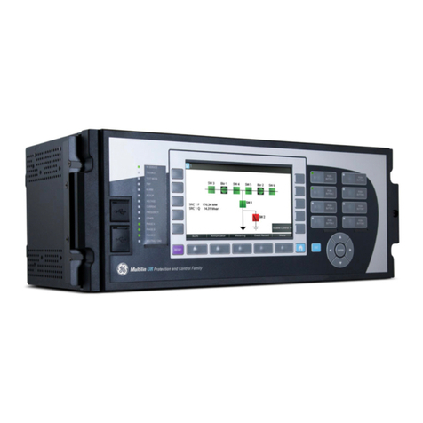
GE MM200 User manual

*1601-9030-A7*
MM200
Motor Management System
Low voltage motor protection and control
GE
Grid Solutions
LISTED
52TL
IND.CONT. EQ.
E83849
Quick Start Guide
MM200 Revision: 1.2x
Manual P/N: 1601-9030-A7
Manual Order Code: GEK-113401F

© 2015 GE Multilin Incorporated. All rights reserved.
GE Multilin MM200 Motor Management System QuickStart Guide for revision 1.2x.
MM200 Motor Management System, EnerVista, EnerVista Launchpad, EnerVista MM300/
MM200 Setup, and FlexLogic are registered trademarks of GE Multilin Inc.
The contents of this manual are the property of GE Multilin Inc. This documentation is
furnished on license and may not be reproduced in whole or in part without the permission
of GE Multilin. The content of this manual is for informational use only and is subject to
change without notice.
Part number: 1601-9030-A7 (November 2015)

MM200 MOTOR MANAGEMENT SYSTEM – QUICK START GUIDE
Storage
Store the unit indoors in a cool, dry place. If possible, store in the original packaging. Follow
the storage temperature range outlined in the Specifications.
To avoid deterioration of electrolytic capacitors, power up units that are stored in a de-
energized state once per year, for one hour continuously.
Warranty
For products shipped as of 1 October 2013, GE warrants most of its GE manufactured
products for 10 years. For warranty details including any limitations and disclaimers, see
our Terms and Conditions at https://www.gegridsolutions.com/multilin/warranty.htm
For products shipped before 1 October 2013, the standard 24-month warranty applies.
Repairs
The firmware and software can be upgraded without return of the device to the factory.
For issues not solved by troubleshooting, the process to return the device to the factory for
repair is as follows:
• Contact a GE Grid Solutions Technical Support Center. Contact information is found in
the first chapter.
• Obtain a Return Materials Authorization (RMA) number from the Technical Support
Center.
• Verify that the RMA and Commercial Invoice received have the correct information.
• Tightly pack the unit in a box with bubble wrap, foam material, or styrofoam inserts or
packaging peanuts to cushion the item(s). You may also use double boxing whereby
you place the box in a larger box that contains at least 5 cm of cushioning material.
• Ship the unit by courier or freight forwarder, along with the Commercial Invoice and
RMA, to the factory.
Customers are responsible for shipping costs to the factory, regardless of whether the
unit is under warranty.
• Fax a copy of the shipping information to the GE Grid Solutions service department.
Use the detailed return procedure outlined at
https://www.gegridsolutions.com/multilin/support/ret_proc.htm
The current warranty and return information are outlined at
https://www.gegridsolutions.com/multilin/warranty.htm
This product cannot be disposed of as unsorted municipal waste in the European
Union. For proper recycling return this product to your supplier or a designated
collection point. For more information go to www.recyclethis.info.

TABLE OF CONTENTS
MM200 MOTOR MANAGEMENT SYSTEM – QUICKSTART GUIDE toc–1
Table of Contents
OVERVIEW
Cautions and Warnings ....................................................................................................................... 2
Safety words and definitions ......................................................................................................................2
General Safety Precautions - MM200.....................................................................................................3
For Further Assistance.......................................................................................................................... 4
INSTALLATION
Mechanical installation ........................................................................................................................ 5
Dimensions..........................................................................................................................................................5
Product identification .....................................................................................................................................6
Mounting ..............................................................................................................................................................7
Electrical installation ............................................................................................................................. 8
Full-voltage non-reversing starter ........................................................................................................ 12
RS485 connections....................................................................................................................................... 13
Control panel...........................................................................................................................................14
Basic control panel....................................................................................................................................... 14
SETPOINTS
Understanding setpoints...................................................................................................................17
Configuration setpoints......................................................................................................................17
Motor setpoints .............................................................................................................................................. 17
Current transformers................................................................................................................................... 19
PROTECTION ELEMENTS
Thermal protection...............................................................................................................................21
Overload curve ...............................................................................................................................................21
COMMUNICATIONS INTERFACES
SPECIFICATIONS
Protection specifications...................................................................................................................27
User interface specifications...........................................................................................................28
Control specifications .........................................................................................................................29
Inputs specifications............................................................................................................................29
Outputs specifications........................................................................................................................30
Power supply specifications ............................................................................................................30
Communications specifications.....................................................................................................30
Testing and certification....................................................................................................................31
Physical specifications........................................................................................................................32
Environmental specifications..........................................................................................................32
MM200 ORDER CODES
Example of an MM200 order code................................................................................................35
MAINTENANCE
General Maintenance..........................................................................................................................37
In-service maintenance .............................................................................................................................37

toc–2 MM200 MOTOR MANAGEMENT SYSTEM – QUICKSTART GUIDE
TABLE OF CONTENTS
Out-of-service maintenance ....................................................................................................................37
Unscheduled maintenance (system interruption) ..........................................................................38
Backup and restore settings ...........................................................................................................38
Backing up settings.......................................................................................................................................38
Restoring settings ..........................................................................................................................................38
Upgrading firmware .....................................................................................................................................39
Upgrading the software..............................................................................................................................40
Uninstalling files and clearing data.......................................................................................................40

MM200 MOTOR MANAGEMENT SYSTEM – QUICK START GUIDE 1
MM200 Motor Management System
Chapter 1: Overview
GE
Grid Solutions
Over view
The MM200 is a motor protection and control system designed specifically for low-voltage
motor applications. The MM200 provides the following key benefits.
• Protection, control, and communication options to suit low-voltage motor
applications.
• Small footprint designed specifically for IEC and NEMA MCC applications.
• DIN rail Mounting.
• Multiple communication protocols allows simple integration into monitoring and
control systems.
• Optional basic control panel interface provides local control and access to system
information.

2MM200 MOTOR MANAGEMENT SYSTEM – QUICK START GUIDE
CAUTIONS AND WARNINGS CHAPTER 1: OVERVIEW
Figure 1-1: Single line diagram
Table 1-1: MM200 protection functions
Cautions and Warnings
Before attempting to install or use the device, review all safety indicators in this document
to help prevent injury, equipment damage, or downtime.
Safety words and definitions
The following symbols used in this document indicate the following conditions
RS485 - Modbus RTU
Profibus/DeviceNet
52
METERING
A
51R 49 37 46
50G
MOTOR
LOAD
Temperature
Thermistor
Phase CT 3
Ground CT 1
Power Fuse
BUS
MM200
MOTOR MANAGEMENT SYSTEM
Contactor
888739A2.CDR
LO: 7 inputs and 3 outputs
HI: 6 inputs and 3 outputs
LO:24VDC
HI:84to250VDC/60to300VAC
ANSI device Description
37 Undercurrent and underpower
46 Current unbalance
49 Thermal overload
50G Ground instantaneous overcurrent
51R Locked/stalled rotor, mechanical jam

CHAPTER 1: OVERVIEW CAUTIONS AND WARNINGS
MM200 MOTOR MANAGEMENT SYSTEM – QUICK START GUIDE 3
DANGER: Indicates a hazardous situation which, if not avoided, will result in death or serious
injury.
IMPORTANT: Indicates a hazardous situation which, if not avoided, could result in death or serious
injury.
CAUTION: Indicates a hazardous situation which, if not avoided, could result in minor or
moderate injury.
NOTE
NOTE: Indicates practices not related to personal injury.
General Safety Precautions - MM200
CAUTION: Failure to observe and follow the instructions provided in the equipment manual(s)
could cause irreversible damage to the equipment and could lead to property damage,
personal injury and/or death.
Before attempting to use the equipment, it is important that all danger and caution
indicators are reviewed.
If the equipment is used in a manner not specified by the manufacturer or functions
abnormally, proceed with caution. Otherwise, the protection provided by the
equipment may be impaired and can result in Impaired operation and injury.
Caution: Hazardous voltages can cause shock, burns or death.
Installation/service personnel must be familiar with general device test practices,
electrical awareness and safety precautions must be followed.
Before performing visual inspections, tests, or periodic maintenance on this device or
associated circuits, isolate or disconnect all hazardous live circuits and sources of
electric power.
Failure to shut equipment off prior to removing the power connections could expose
you to dangerous voltages causing injury or death.
All recommended equipment that should be grounded and must have a reliable and
un-compromised grounding path for safety purposes, protection against
electromagnetic interference and proper device operation.
Equipment grounds should be bonded together and connected to the facility’s main
ground system for primary power.
Keep all ground leads as short as possible.
At all times, equipment ground terminal must be grounded during device operation
and service.
In addition to the safety precautions mentioned all electrical connections made must
respect the applicable local jurisdiction electrical code.
Before working on CTs, they must be short-circuited.

4MM200 MOTOR MANAGEMENT SYSTEM – QUICK START GUIDE
FOR FURTHER ASSISTANCE CHAPTER 1: OVERVIEW
For Further Assistance
For product support, contact the information and call center as follows:
GE Grid Solutions
650 Markland Street
Markham, Ontario
Canada L6C 0M1
Worldwide telephone: +1 905 927 7070
Europe/Middle East/Africa telephone: +34 94 485 88 54
North America toll-free: 1 800 547 8629
Fax: +1 905 927 5098
Website: http://www.gegridsolutions.com/multilin

MM200 MOTOR MANAGEMENT SYSTEM – QUICK START GUIDE 5
MM200 Motor Management System
Chapter 2: Installation
GE
Grid Solutions
Instal lati on
Mechanical installation
This section describes the mechanical installation of the MM200 system, including
dimensions for mounting.
Dimensions
The MM200 is packaged in a fixed format divided into three specific sections.
The dimensions of the MM200 are shown below. Additional dimensions for mounting are
shown in the following sections.

6MM200 MOTOR MANAGEMENT SYSTEM – QUICK START GUIDE
MECHANICAL INSTALLATION CHAPTER 2: INSTALLATION
Figure 2-1: MM200 dimensions
Product identification
The product identification label is located on the side panel of the MM200. This label
indicates the product model, serial number, firmware revision, and date of manufacture.
Figure 2-2: MM200 Identification label
888748A1.CDR
Model:
Serial Number:
Firmware: Mfg.Date:

CHAPTER 2: INSTALLATION MECHANICAL INSTALLATION
MM200 MOTOR MANAGEMENT SYSTEM – QUICK START GUIDE 7
Figure 2-3: MM200 ratings label
Mounting
The MM200 is DIN rail mounted.
The standard DIN rail mounting is illustrated below. The DIN rail conforms to EN 50022.
CAUTION: To avoid the potential for personal injury due to fire hazards, ensure the unit is
mounted in a safe location and/or within an appropriate enclosure.
Figure 2-4: DIN rail mounting

8MM200 MOTOR MANAGEMENT SYSTEM – QUICK START GUIDE
ELECTRICAL INSTALLATION CHAPTER 2: INSTALLATION
Electrical installation
This section describes the electrical installation of the MM200 system. An overview of the
MM200 terminal connections is shown below.
CAUTION: MM200 is not to be used in any way other than described in this manual.
Figure 2-5: MM200 terminal connection overview
A Modbus RTU RS485 port, a thermistor input, and a 50:0.025 CBCT input are provided.
Profibus and Devicenet are provided as options.
Table 2-1: Slot position
Figure 2-6: MM200 terminal connection torque rating
Slot Type
A PSU/Inputs/Control Panel
BCPU/CTs
C Outputs/CBCT/Thermistor/RS485
Control Panel
Profibus or DeviceNet
Optional fieldbus protocols
888740A2.CDR
CTs
PSU
Inputs
RS485
Thermistor
CBCT
2 x Form A
1 x Form C
connector screw torque
CT 4.5 lb-in
IPS, output 5.0 lb-in
Fieldbus, 3.0 lb-in
Thermistor & RS485

CHAPTER 2: INSTALLATION ELECTRICAL INSTALLATION
MM200 MOTOR MANAGEMENT SYSTEM – QUICK START GUIDE 9
CAUTION: Use gauge size appropriate for the voltage and current draw of the device.
Table 2-2: Wire Gauge Sizes
NOTE
NOTE: It is recommended that you install a circuit disconnection system for control power, near
the device, which should be easily accessible after installation of the unit. This is in case an
emergency power shut-down of the unit is required.
Figure 2-7: Top and Rear panel arrangement
The MM200 I/O terminals are labeled with a two-character identifier. The first character
identifies slot position and the second identifies the terminal.
Slot A PSU and Inputs 12 AWG (2.5 mm2) (5.00mm pitch terminals)1
1.Wire gauge size remains constant; increased pitch distance reflects higher voltage rating.
Slot B Fieldbus,
CT Connections
16 AWG (1.5 mm2) (3.50mm pitch terminals)12 AWG
(2.5 mm2) (7.62mm pitch terminals)1
Slot C RS485 & ThermistorOutput Relays,
CBCT
16 AWG (1.5 mm2) (3.50mm pitch terminals12 AWG
(2.5 mm2) (5.00mm pitch terminals)1

10 MM200 MOTOR MANAGEMENT SYSTEM – QUICK START GUIDE
ELECTRICAL INSTALLATION CHAPTER 2: INSTALLATION
CAUTION: Check the voltage rating of the unit before applying control power! Control power
outside of the operating range of the power supply will damage the MM200.
Figure 2-8: CBCT ground CT connection
HI
LO
888351A3-P2
888741A3.CDR
A
C
B
Contactor
Contactor
TO
CONTROL
PANEL
C1
C2
C4
C3
C5
C6
MM200
Motor Management System
C8
C9
C10
C7
Two form-A
contact outputs
CONTACT OUTPUT 2
One form-C
contact output
CONTACT OUTPUT 1
CONTACT OUTPUT 3
THERMISTOR
CBCT
RS485
R
I
-
+
-
+
C
B3 B4 B5 B6 B7 B8
IRIRIR
CT1 CT2 CT3
CT MODULE
RJ45
PROFIBUS OR DEVICENET
V- LHV+
MOTOR
M
M
SG
LO and HI inputs
- see below -

CHAPTER 2: INSTALLATION ELECTRICAL INSTALLATION
MM200 MOTOR MANAGEMENT SYSTEM – QUICK START GUIDE 11
Figure 2-9: CBCT ground CT connection - LO and HI inputs
The exact placement of a zero-sequence CT to detect only ground fault current is shown
below. If the core balance CT is placed over shielded cable, capacitive coupling of phase
current into the cable shield during motor starts may be detected as ground current unless
the shield wire is also passed through the CT window. Twisted-pair cabling on the zero-
sequence CT is recommended.
Figure 2-10: Core balance ground CT installation, shielded cable
M
-
+
A1
A2
A4
A3
A5
A6
A8
A9
A10
A7
+
-
24 VDC CONTACT INPUTS
CONTROL
POWER (VDC)
CONTROL
POWER
24 VDC
FIELD STOP
FIELD START
RESET
M
N
L
A1
A2
A4
A3
A5
A6
A8
A9
A10
L
N
VAC CONTACT INPUTS
CONTROL
POWER (VAC)
CONTROL
POWER
VAC
FIELD STOP
FIELD START
RESET
NR
LO HI
888742A3.cdr
RETURN
NOTE: AC power and AC input wiring shown.
POWER CABLE
TO MOTOR
TO STARTER
GROUND BUS
CABLE LUGS
TO SOURCE
TERMINATION
(TWISTED PAIR)
SPLIT-BOLT CONNECTOR
888712A1.CDR
CORE BALANCE CT
SECONDARY CONNECTION
TO MM200 IED
IMPORTANT: FOR SHIELDED
CABLE, THE GROUND WIRE
MUST PASS THROUGH THE
CT WINDOW.
50:0.025 CORE BALANCE CT
FOR GROUND SENSING
STRESS CONE
SHIELD GROUND
CONNECTION
BOTTOM OF
MOTOR STARTER
COMPARTMENT

12 MM200 MOTOR MANAGEMENT SYSTEM – QUICK START GUIDE
ELECTRICAL INSTALLATION CHAPTER 2: INSTALLATION
Figure 2-11: Core balance ground CT installation, unshielded cable
Full-voltage non-reversing starter
Figure 2-12: Full-voltage non-reversing starter wiring
POWER CABLE
TO MOTOR
50:0.025 CORE BALANCE CT
FOR GROUND CT SENSING
TO STARTER
GROUND BUS
CABLE LUGS TO SOURCE
TERMINATION
(TWISTED-PAIR)
888713A1.CDR
GROUND CONDUCTOR DOES
NOT PASS THROUGH CT, AS THE
CT IS NOT MOUNTED OVER
GROUND WITHIN THE CABLE
JACKET.
BOTTOM OF
MOTOR STARTER
COMPARTMENT
CORE BALANCE CT
SECONDARY CONNECTION
TO MM200 IED
888741A3.CDR
A
C
B
Contactor
Contactor
TO
CONTROL
PANEL
C1
C2
C4
C3
C5
C6
MM200
Motor Management System
C8
C9
C10
C7
Two form-A
contact outputs
CONTACT OUTPUT 2
One form-C
contact output
CONTACT OUTPUT 1
CONTACT OUTPUT 3
THERMISTOR
CBCT
RS485
R
I
-
+
-
+
C
B3 B4 B5 B6 B7 B8
IRIRIR
CT1 CT2 CT3
CT MODULE
RJ45
PROFIBUS OR DEVICENET
V- LHV+
MOTOR
M
M
SG
LO and HI inputs
- see below -

CHAPTER 2: INSTALLATION ELECTRICAL INSTALLATION
MM200 MOTOR MANAGEMENT SYSTEM – QUICK START GUIDE 13
Figure 2-13: LO and HI inputs
The full-voltage non-reversing starter type is a full voltage or across-the-line non-reversing
starter.
When a start control is received, the pre-contactor relay (if any) is picked up for the set pre-
contactor time. When the pre-contactor timer times out, relay contact output 1 closes and
seals-in, picking up contactor M, which starts the motor. When a stop control is received,
relay contact output 1 drops out, contactor M drops out, and the motor stops. The pre-
contactor is omitted on forced starts (for example, External Start).
RS485 connections
Figure 2-14: Typical RS485 connection
M
-
+
A1
A2
A4
A3
A5
A6
A8
A9
A10
A7
+
-
24 VDC CONTACT INPUTS
CONTROL
POWER (VDC)
CONTROL
POWER
24 VDC
FIELD STOP
FIELD START
RESET
M
N
L
A1
A2
A4
A3
A5
A6
A8
A9
A10
L
N
VAC CONTACT INPUTS
CONTROL
POWER (VAC)
CONTROL
POWER
VAC
FIELD STOP
FIELD START
RESET
NR
LO HI
888742A1.cdr
RETURN
NOTE: AC power and AC input wiring shown.
Connect NR to Neutral if DC power supply used.
SCADA, PLC, OR
PERSONAL COMPUTER
COM
OPTOCOUPLER
DATA
MM200 IED
SHIELD
888745A1.CDR
UP TO 32 MM200
OR OTHER IEDs,
MAXIMUM CABLE
LENGTH OF
1200 m (4000 ft.)
LAST
DEVICE
(*) TERMINATING IMPEDANCE AT EACH END
(typically 120 ohms and 1 nF)
TWISTED PAIR
ZT(*)
RS485 +
RS485 -
COMMON
RS485 +
RS485 -
COMMON
IED
RS485 +
IED
RS485 -
COMMON
GROUND THE SHIELD AT THE
SCADA/PLC/COMPUTER ONLY
OR THE MM200 ONLY
DATA
OPTOCOUPLER
ZT(*)
+
-
C

14 MM200 MOTOR MANAGEMENT SYSTEM – QUICK START GUIDE
CONTROL PANEL CHAPTER 2: INSTALLATION
One two-wire RS485 port is provided. Up to 32 MM200 IEDs can be daisy-chained together
on a communication channel without exceeding the driver capability. For larger systems,
additional serial channels must be added. Commercially available repeaters can also be
used to add more than 32 relays on a single channel. Suitable cable should have a
characteristic impedance of 120 ohms and total wire length should not exceed 1200
meters (4000 ft.). Commercially available repeaters will allow for transmission distances
greater than 1200 meters.
Voltage differences between remote ends of the communication link are not uncommon.
For this reason, surge protection devices are internally installed across all RS485 terminals.
Internally, an isolated power supply with an optocoupled data interface is used to prevent
noise coupling.
CAUTION: To ensure that all devices in a daisy-chain are at the same potential, it is imperative
that the common terminals of each RS485 port are tied together and grounded only
once, at the master or at the MM200. Failure to do so may result in intermittent or
failed communications.
The source computer/PLC/SCADA system should have similar transient protection devices
installed, either internally or externally. Ground the shield at one point only, as shown in the
figure above, to avoid ground loops.
Correct polarity is also essential. The MM200 IEDs must be wired with all the positive (+)
terminals connected together and all the negative (–) terminals connected together. Each
relay must be daisy-chained to the next one. Avoid star or stub connected configurations.
The last device at each end of the daisy-chain should be terminated with a 120 ohm
¼ watt resistor in series with a 1 nF capacitor across the positive and negative terminals.
Observing these guidelines will ensure a reliable communication system immune to
system transients.
Control panel
This section provides an overview of the interfacing methods available with the MM200.
For additional details on interface parameters (for example, settings, actual values, etc.),
refer to the individual chapters.
There are two methods of interfacing with the MM200 Motor Management System.
• Via the basic control panel.
• Via the EnerVista MM200 Setup software.
NOTE
NOTE: For full details on handling the EnerVista MM200 Setup software, please use the EnerVista
MM200 Setup Software Guide which accompanies this manual.
Basic control panel
The MM200 basic control panel provides the basic start and stop panel functionality, as
well as a series of LED indications. The basic control panel is illustrated below.

CHAPTER 2: INSTALLATION CONTROL PANEL
MM200 MOTOR MANAGEMENT SYSTEM – QUICK START GUIDE 15
Figure 2-15: Basic control panel
The following LEDs are provided:
• Two USER LEDs (USER 1 and USER 2). the user can select parameters from a list
• 50%/80%/100% - showing motor load
• RUNNING, STOPPED, TRIPPED, and ALARM
• COMMS OK
•AUTOandMANUAL
888750A1.CDR
Other manuals for MM200
1
Table of contents
Other GE Relay manuals