GE Druck TRX-II User manual

GE
Sensing
Druck TRX-II and TRX-II IS
Multi-function Calibrator
User manual - K319
[EN] English 1 ... 50
[FR] French 1 ... 50
[DE] German 1 ... 52
[IT] Italian 1 ... 50
[ES] Spanish 1 ... 50
[PT] Portuguese 1 ... 52


K319 Issue 2 EN-i
English
Table of Contents
INTRODUCTION ..............................................................................1
The TRX-II calibrator ........................................................................1
Pressure Measurements and Calibrations........................................1
Automatic Calibration........................................................................1
Standard Accessories.......................................................................1
Optional Accessories ........................................................................1
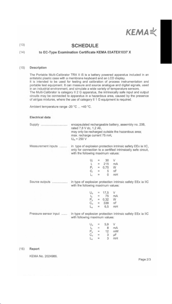
FUNCTIONALITY.............................................................................2
Parts Identification ......................................................................2
Screens to work with ......................................................3
Keys to work with ........................................................................3
Functional Modes .............................................................................4
Keystroking .......................................................................................5
POWER SOURCES .........................................................................6
SET-UP.............................................................................................8
Language Setting..............................................................................8
Date and Time Settings ....................................................................8
Temperature Setting .........................................................................8
Pressure Units Setting......................................................................9
Access Code Settings.......................................................................9
Pressure Sensors ...........................................................................10
Calibration.......................................................................................10
System Setting................................................................................11
TO MEASURE ELECTRICAL SIGNALS .......................................13
Millivolts ..........................................................................................13
Volts................................................................................................13
Milliamps/XMT ................................................................................13
Ohms ..............................................................................................14
Frequency.......................................................................................14
Counter ...........................................................................................15
Switch Contact Position Test ..........................................................15
Circuit Continuity Tester .................................................................16
THERMOCOUPLE MEASUREMENTS..........................................17
Using compensation wires..............................................................17
Using standard test leads (copper wires) .......................................17
TO MEASURE A RTD....................................................................18
TO MEASURE PRESSURE ...........................................................19
The TRX-II Pressure Sensor Option...............................................19
Preparation .....................................................................................19
General ...........................................................................................19
Operating the TRX-II with Pressure Sensor ...................................19
SPECIAL MEASUREMENT FUNCTIONS .....................................22
Scaled Readings.............................................................................22
SOURCING OF ELECTRICAL SIGNALS......................................23

EN-ii K319 Issue 2
Menu Selections ............................................................................ 23
Millivolts ......................................................................................... 24
Volts ............................................................................................... 24
Milliamps/XMT ............................................................................... 24
Ohms ............................................................................................. 25
Frequency ...................................................................................... 25
Counter .......................................................................................... 26
TO SIMULATE A THERMOCOUPLE ........................................... 27
TO SIMULATE A RTD................................................................... 27
SPECIAL SOURCE/SIMULATION FUNCTIONS.......................... 28
Step Mode...................................................................................... 28
Automatic Ramp Mode .................................................................. 29
TRANSMITTER CALIBRATION ................................................... 31
Setting-up a Calibration ................................................................. 31
To Check or Calibrate a Transmitter.............................................. 31
Pressure Transmitter Calibrations ................................................. 32
TRANSMITTER SIMULATION...................................................... 33
Setting-up a Simulation.................................................................. 33
To Simulate a Transmitter.............................................................. 33
PROGRAMMABLE SIGNAL CONVERTER ................................. 34
CE REMARKS............................................................................... 35
SUPPLEMENT FOR INTRINSICALLY SAFE CALIBRATOR
TRX-II IS ........................................................................................ 36
SERVICE, REPAIR AND PARTS.................................................. 39
Recalibration of the TRX-II............................................................. 39
Pressure Sensor ............................................................................ 40
Fault Finding Procedures ............................................................... 41
Spare Parts List TRX-II .................................................................. 43
SPECIFICATIONS - TRX-II ........................................................... 44
Standard Specification ................................................................... 44
Pressure Sensors (optional) .......................................................... 48
Protocol for RS232 System Integration.......................................... 49
Return Goods Procedure ............................................................... 50

K319 Issue 2 EN-iii
English
IMPORTANT NOTE
Unless otherwise indicated in the text, the operating instructions
contained in this publication apply to both the TRXII Multi-Calibrator
instruments and the TRXII IS Multi-Calibrator instruments.
Only the intrinsically safe version of this Multi-Calibrator instrument
(TRX II IS) may be used in hazardous areas and the following
general warnings and conditions of use summarized below are
applicable. Pages 36 to 38 provide supplementary information for
the intrinsically safe variants
Before using TRXII IS, intrinsically safe versions of this Multi-
Calibrator, read the following warnings and read and fully understand
the special conditions of use detailed in the attached certificate of
compliance. IF UNSURE, CHECK BEFORE USE.
BEFORE USE.
WARNINGS
1. DO NOT exceed the maximum measurement ratings given on
page 2 of the Certificate of Compliance.
2. DO NOT open the instrument case in a hazardous area.
3. Batteries must ONLY be fitted in a SAFE AREA.
4. If fitted with rechargeable batteries, the batteries must ONLY be
charged in a safe area and only with the charger Type 13603
supplied for use with the Multi-Calibrator.
5. The RS232 communication circuit may only be used outside the
hazardous area.
6. When the Multi-Calibrator, Type TRXII IS, is used as a source for
intrinsically safe apparatus, that apparatus may not be connected
to any other intrinsically safe circuit simultaneously. The
parameters of the apparatus must comply with the output
parameters of the Multi-Calibrator.
7. To prevent electrical shocks or damage to the instrument, do not
connect more than 30 V between the terminals, or between the
terminals and the ground (earth).

EN-iv K319 Issue 2

K319 Issue 2 EN-v
English

EN-vi K319 Issue 2

K319 Issue 2 EN-vii
English

EN-viii K319 Issue 2
Blank page

K319 Issue 2 EN-1
English
INTRODUCTION
The TRX-II Calibrator
The Multi-Calibrator model TRX-II has been designed for testing and
calibration of process instrumentation and portable test equipment.
The unit provides data to comply with the ISO 9000 requirements for
calibration. The TRX-II can be used to measure and source
analogue and digital signals often used in an industrial environment.
It can also be used to simulate a wide variety of temperature sensors.
Measurement and source/simulation functions can be operated and
read simultaneously.
Model TRX-II IS marked with label “Ex” has been built in accordance
with European Norm II 2 (1) G EEx ia IIC T5 and may be used in IEC
defined zones 0,1 and 2. for special precautions for use deviations to
the standard unit see the chapter “SUPPLEMENT FOR
INTRINSICALLY SAFE CALIBRATOR TRX-II iS”.
Pressure Measurements and Calibrations
A range of pressure sensors is optionally available for pressure
measurements and calibration.
Automatic Calibration
To automate calibration routines and to store calibration data the unit
has been provided with a memory card slot. For the same purpose
the unit has a RS232 cable connector to interface directly with a
Personal Computer. To perform automatic calibration, in the field or
in the workshop, the TRX-II is supported by a Druck Calibration
Management software. The software package and Memory Cards
are optionally available from your local Druck Sales Office or
Distributor.
Standard Accessories
The standard TRX-II Calibrator is packed together with the following
parts:
Operating Manual
Test leads (5x)
Carrying Case
Alkaline Batteries LR14 or C (4x)
Spare fuses 400 mA (3x)
Calibration certificate
Optional Accessories
Line Adaptor/Charger 230 V #13603/230
Line Adaptor/Charger 115 V #13603/115
Line Charger 230 V #13603/230 iS
Line Charger 115 V #13603/115 iS
Pressure Sensors
Calibration Management Software

EN-2 K319 Issue 2
FUNCTIONALITY
Parts Identification ( )
1. POWER switch
Switch the calibrator "ON" and "OFF".
2. EXT. POWER MEASURE
Connector for external power source.
Only suitable for optional line adaptor/charger #13603.
3.* Battery compartment cover
Release screws to get access to batteries.
4.* Battery selector switch
To select Alkaline or Rechargeable batteries.
IMPORTANT:
Switch position must comply with the installed battery type.
5.* Spare fuse
For replacement of a blown fuse.
6.* Fuse mA, Fuse holder
Protects the milliamps measurement circuit.
7. Fuse ohms, Fuse holder
Protects the ohms/RTD measurement circuit.
8. Source terminals for 4 mm plugs
Suitable for standard test leads.
9. Source terminals for wire leads and 4 mm plugs
Suitable for compensation wire leads and standard test leads.
10. Measure terminals for 4 mm plugs
Suitable for standard supplied test leads.
11. Measure terminals for wire leads and 4 mm plugs
Suitable for compensation wire leads and standard test leads.
12. RS232 Connector
To interface directly with Personal Computers.
[Use is optional with compatible software]
13.*Memory card slot *
(PCMCIA)
To interface indirectly with Personal Computers.
[Use is optional with compatible software]
14. Auxiliary Connectors
For use with pressure sensors.
[Do not make any other connections to these terminals]
15. Key-pad numeric
Contains numeric and operating keys.
16. Display
17. Key-pad documenting
Contains keys dedicated for data storage.
* Not Applicable for Model TRX-II IS
[contact your local agent for a list of compatible software]

K319 Issue 2 EN-3
English
Screens to work with
The TRX-II has four types of screen display to work with:
• Menu Selection Screen ( )
Offers selection of choices. Move cursor with arrow keys to your
choice.
• Set-up Screen ( )
Move cursor with arrow keys to fill in the blanks.
• Working Screen ( )
Displays readings of measured and generated values. Source or
simulated temperatures are set with the numerical key-pad or
can be ramped up and down in different ways.
•HelpScreen
Your guide, available in many operational situations. Press INFO
to call a Help screen.
Note:
After switching the calibrator on, the
display screen will be as shown (left)
• Battery type
• Battery voltage
• TRX-II Serial No
• EPROM versions installed
•DATE/TIME
• Days left to next calibration
Keys to work with ( )
• The EXE key
Pressing this key will execute choices or source level
adjustments.
• The CE key
Press to cancel your previous key operation or to correct a typing
error.
• The NUMERICAL key-pad
Used to dial source levels or simulated temperatures. Also used
to fill out levels and time settings for special functions.
• The ARROW keys
Moves the cursor position and ramps source levels up or down.
• The # key
Used in combination with other keys for special functions. Press
# first and hold, while pressing the next key:
# + Numerical key 1-9
Stores key-pad operations (Keystroking).
# + CE
Returns directly to the Main Menu.

EN-4 K319 Issue 2
# + EXE
Opens set-up menu.
Opens signal converter set-up screen.
• The RCL key + Numerical key 1-9
Recalls stored key-pad operations (Keystroking). Press RCL first
and hold, while pressing the next key.
• The 0 key
Changes the sign when display reads all zeros.
• The zero key
To reset the pressure sensor reading at zero. To reset counter/
totalizer function to zero.
• The info key
Give additional information at various menus. Calls the Help
screen.
• The key*
Press the light key to switch the back light ON or OFF.
* not applicable for Model TRX-II IS.
The following functions are only available with Software option.
• The Set-up key
Used to access the recording set-up.
• The As Fnd key
To start As Found calibration procedure.
• The Adjust key
To start adjust procedure.
• The As Left key
To start As Left calibration procedure.
• The View key
To view recorded calibration results.
Functional Modes
• Reading measure signals only
Leave the cursor at NONE in the source menu and select the
required measure function.
• Reading source signals only
Leave the cursor at NONE in the measure menu and select the
required source function.
• Simultaneous reading of measure and source signals
Select required measure and source functions. Menu selections
for both measure and source functions are made after each
other. After finishing all the selections for one function, the menu
prompts to proceed to the other function.

K319 Issue 2 EN-5
English
Keystroking
Keystroking is a solution to eliminate time consuming key-pad
operations for frequently used functions. It can store 9 different
sequences of key-pad operations. Recalling a sequence
immediately returns to the function as stored. A sequence from any
operational situation can be recalled.
• Storing a key-pad operation sequence
Perform all key-pad operations for the function required to
"keystroke" up to working screen. Press # and hold while
pressing the numerical key under which required to store the
sequence. To store a new function under a "used" key, repeat
above procedure to overwrite the old function.
• Recalling a key-pad operation sequence
Press RCL and hold, while pressing the appropriate numerical
key. To clear all keystroke memories, press # and EXE to open
the set-up menu.
Select SYSTEM and press EXE. Select CLEAR KEYSTROKE
MEMORY and press EXE again. Press CE to leave the set-up
menu.

EN-6 K319 Issue 2
POWER SOURCES
Power from internal batteries
Internal power is obtained from 4x 1.5 V Alkaline batteries or four
1.2V, rechargeable batteries, Model R14, Baby or C size.
Note: Not applicable for Model TRX-II IS.
Installation of the batteries
Switch the calibrator off before installing new batteries.
Note: Not applicable for Model TRX-II IS.
Release both mounting screws retaining the battery compartment
cover. Remove the old batteries and check that the contact plates
are clean. Place the new batteries in position observing polarity as
indicated.
Use of Alkaline batteries (supplied as standard)
The calibrator is supplied with one set of 4 Alkaline batteries. Check
that the Battery Selector Switch is in the "Alkaline" position before
replacing the batteries. Battery switch position will be confirmed on
the screen during start-up of the calibrator. Replace batteries when
the screen shows the battery symbol.
IMPORTANT:
• Be sure that batteries are inserted so that they are placed correctly
with respect to the (+) and (-) indications in the battery
compartment. If the batteries are not inserted correctly, they may
leak and damage the calibrator.
• Do not mix old and new batteries, or batteries of different types
(such as carbon and alkaline.)
• If the calibrator is not to be used for a long period of time, take out
the batteries.
• Remove and dispose of worn-out batteries.
• Never attempt to recharge or short-circuit the batteries.
Changing from Alkaline to Rechargeable batteries
Remove the Alkaline batteries. Slide the battery type switch to the
"Ni-Cd" position.
Install 4 rechargeable batteries (purchased locally). Battery switch
position will be confirmed on the screen during start-up of the
calibrator. Recharge batteries when the screen shows the battery
symbol.
WARNING:
Never place Alkaline or other non-rechargeable batteries after
setting the switch position to "Ni-Cd".
Recharging batteries
Use the Line Adaptor/Charger #13603 only; other equipment may
cause damage to the calibrator. Check the indicated Line Voltage
and turn the charger switch on. Connect the appropriate Adaptor/
Charger plugs to the line and to the calibrator.
As the adaptor and charger functions are fully independent from each
other, the calibrator can be used while charging.
Recharging time from fully discharged to fully charged is 14 hours.
You may charge for periods longer than 14 hours. Note that at lower
ambient temperatures, the capacity of Ni-Cd batteries is significantly

K319 Issue 2 EN-7
English
lowered. If the batteries do not reach their normal capacity after a 14
hour charging period, cycle complete discharging and charging at
least twice. If the batteries remain weak they should be replaced. No
particular brand of Ni-Cd is recommended although cells rated at 2.0
Ah have preference over the more generally available 1.8 Ah cells.
Operating from 115 V or 230 V line voltage (50 or 60 Hz)
Use the Line Adaptor/Charger #13603 only. Other equipment may
cause damage to the calibrator. Check the indicated line voltage.
Connect the appropriate Line Adaptor/Charger plugs to the line and
to the calibrator.
Note: Not applicable for Model TRX-II iS.

EN-8 K319 Issue 2
SET-UP
Language Setting
The TRX-II has multilingual software. The factory setting is
ENGLISH.
Setting the Language
Leave the cursor at NONE at the measure and source menu and
press # and EXE keys simultaneously to open the Set-up menu.
Select LANGUAGE and press EXE. Select required language and
press EXE. Press CE to leave the set-up menu.
Date and Time Settings
The TRX-II is equipped with a real time clock. At calibration, the
clock is set to Central European Time.
• To record Date and Time on the memory card when using
compatible software;
• To indicate how many days are left before last calibration expires.
Setting the clock to local date and time
Leave the cursor at NONE at the measure and source menu and
press the # and EXE keys simultaneously to open the set-up menu.
Select DATE/TIME. Press EXE again. Select date and enter new
date. Press EXE to accept new date. Repeat the above for time
settings. Press CE to leave the set-up menu.
Temperature Setting
Temperature simulations and measurements can be shown in either
degrees Celsius or degrees Fahrenheit. Factory setting is Celsius.
Readings are based on either IPTS 68 or ITS 90 temperature scales.
Factory setting is IPTS 68.
Changing the temperature units
Leave the cursor at NONE at the measure and source menu and
press the # and EXE keys simultaneously to open the set-up menu.
Select temp. settings and press EXE. Select °C and press EXE to
change from °C to °F or vice versa. Press CE to leave the set-up
menu.

K319 Issue 2 EN-9
English
Changing the temperature scale
Leave the cursor at NONE at the measure and source menu and
press the # and EXE keys simultaneously to open the set-up menu.
Select Temp. settings and press EXE. Select °C and press EXE to
change from °C to °F or vice versa. Press CE to quit the set-up
menu.
Pressure Units Setting
Pressure readings can be shown in different pressure units. The
selection can be made via the Set-up menu.
Changing the pressure units
Leave the cursor at NONE at the measure and source menu and
press # and EXE keys simultaneously to open the set-up menu.
Select PRESSURE UNITS and press EXE. Select one of the 10
different pressure units and press EXE to change. Press CE to leave
the set-up menu.
Note: The reference temperature for in H20 or mH20 automatically
changes according to the defined temperature setting °C or °F.
°C refers to water temperature at 4°C and °F to 68°F.
Access Code Settings
The ACCESS CODE is programmable by the customer. The
following menus are protected by this code;
• ACCESS CODE.
• Calibration menu (Electrical).
• Add pressure sensors.
• Delete pressure sensors.
• Calibration pressure sensors.
Access Code 9410 is the standard factory setting.

EN-10 K319 Issue 2
Changing the ACCESS CODE
Leave the cursor at NONE at the measure and source menu and
press # and EXE simultaneously to open the set-up menu. Select
ACCESS CODE and press EXE.
Type in the access code and press EXE to confirm. You are now in a
mode where you can change the code. If applicable, the new code
can be typed in and confirmed by EXE. 0000 as code is considered
as no existing ACCESS CODE.
Note: Registration of the ACCESS CODE is essential.
Pressure Sensors
This menu enables the user to install and calibrate pressure sensors.
At the end of this manual, a special chapter describes the sensor
installation routine.
Calibration
This menu enables the user to calibrate and adjust the TRX-II. At the
end of this manual a special chapter describes the recalibration
routine. CALIBRATION menu is ACCESS CODE protected.
This manual suits for next models
1
Table of contents
Other GE Test Equipment manuals

GE
GE Druck DPI 150 User manual

GE
GE Druck DPI 610 User manual

GE
GE TVRMS2 Series User manual

GE
GE Druck DPI 620 Genii User manual

GE
GE Druck DPI 832 User manual

GE
GE Druck DPI 832 User manual

GE
GE Druck DPI 841 User manual

GE
GE Druck ADTS 2 Series Use and care manual

GE
GE EVT-Pro User manual

GE
GE Druck DPI 610 User manual
Popular Test Equipment manuals by other brands

Tintometer
Tintometer Lovibond MD100 Manual of Methods

Extech Instruments
Extech Instruments MG320 user manual

Agilent Technologies
Agilent Technologies 85032F User's and service guide

Telegärtner
Telegärtner UCT9 operating instructions

VITO
VITO FT 440 Short instructions

Kingfisher
Kingfisher KI7343C-InGaAs quick start guide