GE Druck ADTS 505 User manual

GE
Measurement & Control
Druck ADTS 505 Air Data Test Set
User Manual K0260

© 2013 General Electric Company. All Rights Reserved. Specifications are subject to change without notice. GE is a
registered trademark of General Electric Company. Other company or product names mentioned in this document may
be trademarks or registered trademarks of their respective companies, which are not affiliated with GE.

i
K0260 Issue No. 8
Introduction
This technical manual provides operating instructions for the Air Data Test System compatible
with the requirements of first line operation for the technician and supervisor.
Scope
This technical manual contains a brief description, operation and testing procedures for the
user of this equipment with software version V1.08.
Safety
The manufacturer has designed this equipment to be safe when operated using the
procedures detailed in this manual. Do not use this equipment for any other purpose than that
stated, the protection provided by the equipment may be impaired.
This publication contains operating and safety instructions that must be followed to make sure
of safe operation and to maintain the equipment in a safe condition. The safety instructions are
either warnings or cautions issued to protect the user and the equipment from injury or
damage.
Use qualified* technicians and good engineering practice for all procedures in this publication.
PIN Protection
The ADTS 505 contains two protected menus, the operating limits (described in this manual)
and the maintain calibration menu (described in the calibration manual).
The factory set PIN codes are contained in an envelope addressed to the Supervisor.
IMPORTANT NOTE
Change these codes for authorised access. Unauthorised access to these two menus can make
this system inaccurate and could, in control mode, cause excessive rates of pressure change.
Pressure
Do not apply pressure greater than the maximum safe working pressure to the equipment.
Toxic Materials
There are no known toxic materials used in this equipment.
Maintenance
The equipment must be maintained using the manufacturer’s procedures and should be
carried out by authorized service agents or the manufacturer’s service departments
Technical Advice
For technical advice contact the manufacturer or subsidiary.
* A qualified technician must have the necessary technical knowledge, documentation, special test
equipment and tools to carry out the required work on this equipment.

ii
K0260 Issue No. 8
Associated Publications
This lists the manuals and publications referenced in this manual.
Calibration Manual K272
Air Data Test Set ADTS 505
Quick Reference Guide K274
Air Data Test Set ADTS 505
Approved Service Agents
Markings and Symbols
This equipment meets the requirements of all relevant European safety directives. The
equipment carries the CE mark.
This symbol, on the instrument, indicates that the user should refer to the user manual. This
symbol, in this manual, indicates a hazardous operation.
Do not dispose of this product as household waste. Use an approved organisation that
collects and/or recycles waste electrical and electronic equipment. For more information,
contact one of these:
• our customer service department (contact us at www.ge-mcs.com)
• your local government office
Approved Service Agents
For a list of approved service agents, visit our website: www.ge-mcs.com
Internet www.ge-mcs.com
Druck ADTS 505 User Manual

iii
K0260 Issue No. 8
Table of Contents
Preliminary pages
Introduction .................................................................................................................................................................................. ............... i
Scope .................................................................................................................................................................................. ............... i
Associated Publication................................................................................................................................................................... ............... ii
Approved Service Agents.............................................................................................................................................................. ............... ii
Table of contents (this table)....................................................................................................................................................... ............... iii
Abbreviations .................................................................................................................................................................................. ............... vii
Glossary .................................................................................................................................................................................. ............... ix
Pressure units and conversion factors................................................................................................................................. ............... xi
Section Title page
1 DESCRIPTION
1.1 Introduction......................................................................................................................................................... ............... 1-1
1.2 Operating Limits............................................................................................................................................... ............... 1-3
2INSTALLATION
2.1 Packaging........................................................................................................................................................... ............... 2-1
2.2 Packaging for Storage and Transportation....................................................................................... ............... 2-1
2.3 Return Goods Procedure............................................................................................................................. ............... 2-3
2.4 Electrical Connection..................................................................................................................................... ............... 2-6
2.5 Pneumatic Pressure Connection............................................................................................................. ............... 2-7
2.6 Positioning of the ADTS 505....................................................................................................................... ............... 2-8
3OPERATION
3.1 Preparation.......................................................................................................................................................... ............... 3-1
3.2 Display Functions and Units of Measure............................................................................................. ............... 3-2
3.3 Quick Reference............................................................................................................................................... ............... 3-3
3.4 First Time Operators....................................................................................................................................... ............... 3-4
3.4.1..... Operating Modes............................................................................................................................ ............... 3-6
3.5 Operation and Example Procedures..................................................................................................... ............... 3-10
3.5.1..... Operating Procedures.................................................................................................................. ............... 3-10
3.5.2..... Power-up............................................................................................................................................. ............... 3-10
3.5.3..... Control or Measure Parameter................................................................................................ ............... 3-11
3.5.4.....Leak Testing the ADTS 505......................................................................................................... ............... 3-11
3.5.5..... Changing the Units of Measurement.................................................................................... ............... 3-13
3.5.6..... Setting Limits..................................................................................................................................... ............... 3-13
3.6 Tests Before Use.............................................................................................................................................. ............... 3-15
3.6.1..... Aircraft System Protection......................................................................................................... ............... 3-15
3.7 Testing Aircraft Systems or UUT.............................................................................................................. ............... 3-15
3.7.1.....Testing the Aircraft Static System........................................................................................... ............... 3-16
3.7.2.....Testing the Aircraft Pitot System............................................................................................. ............... 3-17
3.7.3..... Combined Testing of the Aircraft Pitot and Static Systems........................................ ............... 3-18
3.7.4..... Mach Test and Constant Mach................................................................................................ ............... 3-19
3.7.5..... Leak Testing....................................................................................................................................... ............... 3-20
3.7.6..... Airspeed Switch Test..................................................................................................................... ............... 3-21
3.7.7..... Engine Pressure Ratio (EPR)....................................................................................................... ............... 3-22
3.7.8..... Go To Ground.................................................................................................................................... ............... 3-23
CONTENTS

iv
K0260 Issue No. 8
Table of Contents (contd)
Section Title page
3.8 Manual Venting of the Aircraft Pitot and Static Systems............................................................. ............... 3-24
3.9 ADTS 505 Options............................................................................................................................................ ............... 3-24
3.10 Set-up Reference............................................................................................................................................. ............... 3-25
4MAINTENANCE
4.1 Introduction......................................................................................................................................................... ............... 4-1
4.2 Materials and Tools......................................................................................................................................... ............... 4-2
4.3 Maintenance Tasks......................................................................................................................................... ............... 4-3
4.4 Routine Maintenance..................................................................................................................................... ............... 4-4
5 TESTING AND FAULT FINDING
5.1 Introduction......................................................................................................................................................... ............... 5-1
5.2 Standard Serviceability Test...................................................................................................................... ............... 5-2
5.3 Fault Diagnosis................................................................................................................................................. ............... 5-3
5.4 Warnings and Self-test Errors.................................................................................................................. ............... 5-3
5.5 Further Testing.................................................................................................................................................. ............... 5-6
5.6 Fault Finding....................................................................................................................................................... ............... 5-14
6 REFERENCE and SPECIFICATION
6.1 Introduction......................................................................................................................................................... ............... 6-1
6.2 Key-pad Selections and Functions......................................................................................................... ............... 6-1
F1 - F6................................................................................................................................................................... ............... 6-1
ALT/Ps................................................................................................................................................................... ............... 6-2
SPEED Qc.............................................................................................................................................................. ............... 6-2
MACH..................................................................................................................................................................... ............... 6-3
ROC Ps RATE........................................................................................................................................................ ............... 6-3
RATE....................................................................................................................................................................... ............... 6-4
LEAK MEASURE/CONTROL.......................................................................................................................... ............... 6-5
GROUND................................................................................................................................................................ ............... 6-5
0 to 9...................................................................................................................................................................... ............... 6-6
-000........................................................................................................................................................................ ............... 6-6
CLEAR/QUIT......................................................................................................................................................... ............... 6-6
DELETE................................................................................................................................................................... ............... 6-6
HELP....................................................................................................................................................................... ............... 6-7
ENTER.................................................................................................................................................................... ............... 6-7
CLEAR/QUIT + ENTER (ABORT)................................................................................................................... ............... 6-7
Main Menu........................................................................................................................................................... ............... 6-8
[Rate Timer]......................................................................................................................................................... ............... 6-8
[Units].................................................................................................................................................................... ............... 6-9
[EPR]....................................................................................................................................................................... ............... 6-10
[Hold] ..................................................................................................................................................................... ............... 6-10
Nudge [ or ]............................................................................................................................................... ............... 6-10
6.3 SETUP .................................................................................................................................................................... ............... 6-11
6.3.1.....Set-up 1 of 2....................................................................................................................................... ............... 6-11
............... [Display],[Single, Dual, Quad, Hand Term]........................................................................... ............... 6-11
Druck ADTS 505 User Manual

v
K0260 Issue No. 8
Table of Contents (contd)
Section Title page
[Units].................................................................................................................................................................... ............... 6-12
[Limits]................................................................................................................................................................... ............... 6-13
[Alt. Corr.].............................................................................................................................................................. ............... 6-15
[Date Format]..................................................................................................................................................... ............... 6-16
6.3.2.....Set-up 2 of 2....................................................................................................................................... ............... 6-17
............... [Operational Hours]....................................................................................................................... ............... 6-17
............... [Software Versions]........................................................................................................................ ............... 6-17
............... [Security].............................................................................................................................................. ............... 6-17
............... [Maintain Calibration]................................................................................................................... ............... 6-17
............... [Auto Leak].......................................................................................................................................... ............... 6-18
6.4 Other Features................................................................................................................................................... ............... 6-19
Elapsed Time Counter.................................................................................................................................... ............... 6-19
............... Auto Zero............................................................................................................................................. ............... 6-19
............... Hand Terminal Option A.............................................................................................................. ............... 6-19
............... Hand Terminal Option B.............................................................................................................. ............... 6-19
............... ...............Template Format for Creating Test Sequence Files....................................... ............... 6-32
............... ...............Option B Advanced Hand Terminal Specification........................................... ............... 6-41
6.5 Specification........................................................................................................................................................ ............... 6-42
CONTENTS

vi
K0260 Issue No. 8
Table of Illustrations
Figure Title page
1-1 ADTS 505 General View............................................................................................................................... ............... 1-2
2-1 ADTS 505 Accessories................................................................................................................................... ............... 2-4
2-2 ADTS 505 Altitude Correction On-aircraft........................................................................................... ............... 2-9
2-3 ADTS 505 Altitude Correction Off-aircraft........................................................................................... ............... 2-9
2-4 ADTS 505 General View............................................................................................................................... ............... 2-10
3-1 Key-pad and Display...................................................................................................................................... ............... 3-3
4-1 Fuse Replacement........................................................................................................................................... ............... 4-5
5-1 Fault Finding Chart......................................................................................................................................... ............... 5-4
5-2 System Screen for Diagnosis.................................................................................................................... ............... 5-7
5-3 System Screen................................................................................................................................................... ............... 5-9
5-4 Key-pad Test Display..................................................................................................................................... ............... 5-10
6-1 ARINC 565 Limits Graph.............................................................................................................................. ............... 6-14
6-2 Altitude Correction On-aircraft................................................................................................................ ............... 6-15
6-3 Altitude Correction Off-aircraft................................................................................................................ ............... 6-16
6-4 Interconnection................................................................................................................................................ ............... 6-20
6-5 Power-up Displays.......................................................................................................................................... ............... 6-21
6-6 Main Menu Screen.......................................................................................................................................... ............... 6-22
6-7 Main Menu Structure..................................................................................................................................... ............... 6-23
6-8 Manual Control Selections......................................................................................................................... ............... 6-24
6-9 Set-up Menu Selections............................................................................................................................... ............... 6-27
6-10 Test Sequence Selections........................................................................................................................... ............... 6-30
6-11 Customer Test Sequence File Selections............................................................................................. ............... 6-31
6-12 System Status..................................................................................................................................................... ............... 6-38
6-13 Example Error Screen.................................................................................................................................... ............... 6-39
List of Tables
Table Title page
2-1 Parts List............................................................................................................................................................... ............... 2-5
4-1 Maintenance Chart......................................................................................................................................... ............... 4-1
4-2 Materials List....................................................................................................................................................... ............... 4-2
4-3 Tool and Test Equipment Requirements.............................................................................................. ............... 4-2
5-1 Fault Finding...................................................................................................................................................... ............... 5-5
5-2 System Screen Information....................................................................................................................... ............... 5-8
5-3 Error Messages................................................................................................................................................. ............... 5-14
5-4 Warning Messages......................................................................................................................................... ............... 5-15
Druck ADTS 505 User Manual

vii
K0260 Issue No. 8
Abbreviations
The following abbreviations are used in this manual; the abbreviations are the same in the singular and plural.
AAmpere
abs Absolute
a.c. Alternating current
ADTS Air Data Test Set
ALT Altitude
ARINC Air Radio Incorporated
ASI Airspeed indicator
CAS Calibrated airspeed
COSHH Control of Substances Hazardous to Health Regulations
cm Centimetre
d.c. Direct current
Def Define
e.g. For example
EPR Engine pressure ratio
etc. And so on
°F Degrees Fahrenheit
Fig. Figure
ft Foot
g Gauge
hHour
HBC High breaking capacity
Hg Mercury
hm Hecto metre
Hz Hertz
IAS Indicated airspeed
i.e. That is
in Inch
kg Kilogram
km Kilometre
kts Knots
LCD Liquid crystal display
mMetre
mA Milliampere
max Maximum
mbar Millibar
min Minute or minimum
mm Millimetre
mph Miles per hour
MSDS Material safety data sheet
mV Millivolts
No. Number
PIN Personal identification number
Ps Static pressure
psi Pounds per square inch
Pt Total pressure (Pitot)
Qc Differential pressure Ps-Pt
QFE Local atmospheric pressure
QNH Barometric pressure at sea level
Abbreviations

viii
K0260 Issue No. 8
Abbreviations (contd)
RGA Return Goods Authorization (Druck procedure)
RH Relative humidity
RMS Root mean square
ROC Rate of climb
Rt Rate
SST Standard serviceability test
VVolts
+ve Positive
-ve Negative
°C Degrees Celsius
°F Degrees Fahrenheit
Druck ADTS 505 User Manual
ix
K0260 Issue No. 8
Glossary
Terminology
The terminology used in this manual is specific and individual interpretation must not be
introduced. The terms are defined as follows:
Adjust To bring to amore satisfactory state;to manipulatecontrols, levers, linkages,etc. to return equipment
from an out-of-tolerance condition to an in-tolerance condition.
Align To bring into line; to line up; to bring into precise adjustment, correct relative position or coincidence.
Assemble:To fit and secure together the several parts of; to make or form by combining parts.
Calibrate: To determine accuracy, deviation or variation by special measurement or by comparison with a
standard.
Check: Make a comparison of a measure of time, pressure, temperature, resistance, dimension or other
quality with a known figure for that measurement.
Disconnect:To detach the connection between; to separate keyed or matched equipment parts.
Dismantle:To take apart to the level of the next smaller unit or down to all removable parts.
Examine: To perform a critical visual observation or check for specific conditions; to test the condition of.
Fit: Correctly attach one item to another.
Inspect: Review the work carried out by Specialists to ensure it has been performed satisfactorily.
Install: To perform operations necessary to properly fit an equipment unit into the next larger assembly or
system.
Maintain: To hold or keep in any particular state or condition especially in a state of efficiency or validity.
Operate: Make sure that an item or system functions correctly as far as possible without the use of test
equipment or reference to measurement.
Readjust: To adjust again; to move back to a specified condition; to bring back to an in-tolerance condition.
Reconnect:To rejoin or refasten that which has been separated.
Refit: Fit an item which has previously been removed.
Glossary

x
K0260 Issue No. 8
Remove: To perform operations necessary to take an equipment unit out of the next larger assembly or
system. To take off or eliminate. To take or move away.
Repair: To restore damaged, worn out or malfunctioning equipment to a serviceable, usable or operable
condition.
Replace: Remove an item and fit a new or a serviced item.
Reset: To put back into a desired position, adjustment or condition.
Service: To perform such operations as cleaning, lubricating and replenishing to prepare for use.
Test: Ascertain by using the appropriate test equipment that a component or system functions correctly.
Druck ADTS 505 User Manual
xi
K0260 Issue No. 8
Table of pressure units and conversion factors
Unit Conversion
To convert FROM pressure VALUE 1 in pressure UNITS 1
TO pressure VALUE 2 in pressure UNITS 2, calculate as follows:
VALUE 2 = VALUE 1 x FACTOR 1
FACTOR 2
Note:
The conversion factor for pressure units referenced [1] are calculated for a water temperature
of 4°C. Pressure units referenced [2] are calculated for a water temperature of 68°F these units
are normally used in the USA.
tinuerusserP )slacsaP(rotcaF tinuerusserP )slacsaP(rotcaF
rab000001tf/fbl
2
3088.74
ni/fbl
2
)isp(67.4986gHni93.6833
Hm
2
O56.6089Hni
2
]1[O980.942
rabm001Htf
2
]1[O70.9892
mc/fgk
2
5.66089mta0.523101
m/fgk
2
56608.9tf/ldp
2
61884.1
gHmm223.331mc/nyd
2
1.0
gHmc22.3331rabh00000001
gHm0.223331tf/fnot
2
)KU(0.252701
H/mm
2
]1[O56608.9ni/fnot
2
)KU(00344451
H/mc
2
]1[O5660.89Hni
2
]2[)ASU(O53146.842
m/N
2
1Htf
2
]2[)ASU(O3896.3892
aPh001mm/Pk
2
0566089
aPk0001mc/Pk
2
5.66089
aPM0000001m/Pk
2
56608.9
rrot223.331

xii
K0260 Issue No. 8
Druck ADTS 505 User Manual
Description 1 - 1
K0260 Issue No. 8
1
1INTRODUCTION
1.1 Introduction
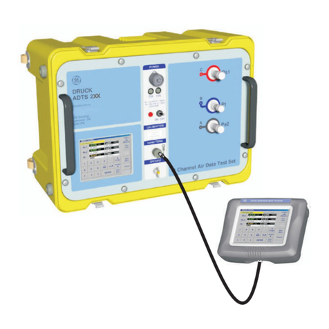
The ADTS 505 is a self-contained flight-line air data test system, enclosed in an ABS case. The
unit provides complete pressure and vacuum measuring and control for on-aircraft sense and
leak testing, functional tests of air data instruments, components and systems.
The ADTS 505 displays and operates in either units of pressure measurement or aeronautical
units. In the control mode, the rate that the pressures change towards new set-points can be
controlled in true aeronautical rate units.
There are two independent pneumatic channels connect to the aircraft or instrument systems,
one for static and one for pitot. They can be operated as measure only channels with leak
testingfacilitiesor eachcan becontrolchannels producingtrue pressureconditions foraltitude
and airspeed. Two pneumatic outlet ports, on the front panel and identified as Ps (static) and
Pt (pitot) provide connection to the aircraft system or unit under test.
To protect sensitive instruments and equipment a `ground' facility automatically and safely
controls both channels to atmospheric pressure at the previously entered rates of change and
then informs the user when both channels are safely at `ground'.
Pre-defined sets of limits, stored in the system, prevent excessive pressures and rates
damaging aircraft systems and components. A further five sets of operating limits can be
defined by the supervisor or quality assurance engineer. The user can select sets of limits but
cannot change the values.
The user interface is either the key-pad and display on the front panel or one of two types of
optional hand terminal connected to the front panel. The two types of hand terminal are
identified as option A and option B.
The option A hand terminal contains all the facilities of the front panel key-pad and display.
The key-pad contains fixed function keys used to select various parameters, modes and enter
numeric values. The display shows various menus, each menu provides selections using six
menu-defined function keys.
The option B advanced hand terminal is a computer-based device that contains all the facilities
of option A on a touch-sensitive, Windows® display, colour screen. It also up-loads and down-
loads user-defined test programs and displays the resulting test data.
The integral pumps of the ADTS 505, produce pressure and vacuum supplies for the unit's
controlling requirements. The power supply connection for the unit is located onthe front panel.

1 - 2 Druck ADTS 505 User Manual
K0260 Issue No. 8
FIGURE 1-1 ADTS 505 GENERAL VIEW
Option A Hand Terminal
Option B Hand Terminal
Air Data Test Set - Hand Terminal
Leak Measure
LEAK MEASURE MODE
Mach
0.001
Mach
DO NOT OBSTRUCT
THESE VENTS
WATER
DRAIN
Advanced Hand TerminalAdvanced Hand Terminal
g
T5.0A
250V
HBC

Description 1 - 3
K0260 Issue No. 8
1
1.2 Operating Limits
The ADTS 505 is supplied with the following pre-defined operating limits.
Civil Limits
Parameter Limit
MIN ALT -1,000 ft
MAX ALT 50,000 ft
MIN CAS 0.0 knots
MAX CAS 450.0 knots
MAX MACH 1.000 Mach
MAX ROC 6,000 ft/min
ARINC LIMITS OFF
ALT CORRECTION 0 ft
MIN Ps 115.972 mbar
MAX Ps 1050.406 mbar
MIN Qc 0.0 mbar
MAX Qc 368.01 mbar
MAX Rate Ps 109.85 mbar/min
MAX Rate Qc 109.85 mbar/min
Standard Limits
Parameter Limit
MIN ALT -2,000 ft
MAX ALT 60,000 ft
MIN CAS 0.0 knots
MAX CAS 650.0 knots
MAX MACH 1.732 Mach
MAX ROC 10,000 ft/min
ARINC LIMITS OFF
ALT CORRECTION 0 ft
MIN Ps 65.00 mbar
MAX Ps 1088.6 mbar
MIN Qc 0.0 mbar
MAX Qc 866.00 mbar
MAX Rate Ps 200 mbar/min
MAX Rate Qc 200 mbar/min

1 - 4 Druck ADTS 505 User Manual

K0260 Issue No. 8
Max Limits
Parameter Limit
MIN ALT -2,000 ft
MAX ALT 60,000 ft
MIN CAS 0.0 knots
MAX CAS 650.0 knots
MAX MACH 2.800 Mach
MAX ROC 40,000 ft/min
ARINC LIMITS OFF
ALT CORRECTION 0 ft
MIN Ps 10.90 mbar
MAX Ps 1355.00 mbar
MIN Qc -1355.00 mbar
MAX Qc 2490.00 mbar
MAX Rate Ps 1000 mbar/min
MAX Rate Qc 1000 mbar/min
EPR Limits
Parameter Limit
MIN INLET 27.0 mbar
MAX INLET 1355.0 mbar
MIN OUTLET 27.0 mbar
MAX OUTLET 2500.0 mbar
MIN EPR 0.1
MAX EPR 10.0
MIN INLET RATE 0
MAX INLET RATE 1000 mbar/min
MIN EPR RATE 0
MAX EPR RATE 60 EPR/min

Druck ADTS 505 User Manual 2 - 1
K0260 Issue No. 8
2
2 INSTALLATION
2.1 Packaging
On receipt of the ADTS 505 check the contents of the packaging against the following lists:
i) ADTS 505 Air Data Test Set
ii) Power supply cable - 5 m, no line plug (regional line plugs require option C)
iii) Option A
comprising:
Hand terminal
Hand terminal cable - 18 m (option A only)
5 m hose - red
5 m hose - blue
Accessory Bag
iv) Option B
comprising:
Advanced hand terminal
Hand terminal cable - 18 m (option B only)
Cable, communications
Cable, power supply
Power pack
Accessory Bag
v) 3 m hose - red
vi) 3 m hose - blue
vii) User Manual (this publication)
viii) Quick Reference Guide K0274
ix) Kit, fuse/o-ring (also see Figure 2-1, item1)
2.2 Packaging for Storage or Transportation
To store the unit or to return the unit for calibration or repair carry out the following procedures:
1. Pack the unit as detailed in the following procedure.
2. To return the unit for calibration or repair complete the return goods procedure as
detailed in 2.3.

2 - 2 Installation
K0260 Issue No. 8
Procedure
The unit should be at zero/ambient pressure. Disconnect the hose assemblies and stow in the
lid.
•Switch OFF and disconnect from the electrical power supply. Disconnect the power
supply cable and the hand terminal cable. Disconnect the hand terminal cable from the
hand terminal.
•Fit the lid to the unit.
•The power supply cable, hand terminal cable and the hand terminal should be placed
in the original packing material.
If available, use the original packing material. When using packing materials other than the
original, proceed as follows.
•Wrap unit in polyethylene sheeting.
•
Select a double-wall cardboard container. Inside dimensions must be at least 15 cm
greater than the equipment. The carton must meet test strength requirements of >125 kg.
•Protect all sides with shock-absorbing material to prevent equipment movement within
the container.
Seal carton with approved sealing tape.
Mark carton “FRAGILE” on all sides, top, and bottom of shipping container.
To return the unit for calibration or repair complete the return goods procedure as detailed in 2.3.
Environment
The following conditions apply for both shipping and storage:
•Temperature Range........... ............-20 to +70°C (-4 to +158°F)
•Altitude......... ............Up to 15,000 feet (4,570 metres)
Table of contents
Other GE Test Equipment manuals

GE
GE XL VU User manual

GE
GE Druck DPI 620 Genii User manual

GE
GE PACE Series User manual

GE
GE NOVA Parts list manual

GE
GE Druck DPI 620-IS User manual

GE
GE MicroVersaTrip TVTS1 User manual

GE
GE Druck DPI612 User manual

GE
GE EVT-Pro 2.0 User manual

GE
GE Druck ADTS 405 R/F Mk2 User manual

GE
GE Multilin EPM 7000 User manual