GE Druck DPI 610 User manual

i K0430 Issue No. 2
WARNING
Before operating this intrinsically safe instrument, read the safety instructions and
the special conditions stated on the ATEX certificate (Appendix 2)
Safety
The manufacturer has designed this equipment to be safe when operated using the
procedures detailed in this manual. Do not use this equipment for any other purpose
than that stated.
This publication contains operating and safety instructions that must be followed to
ensure safe operation and to maintain the equipment in a safe condition. The safety
instructions are either warnings or cautions issued to protect the user and the equipment
from injury or damage.
Use suitably qualified * technicians and good engineering practice for all procedures in
this publication.
Pressure
Do not apply pressures greater than the safe working pressure to this equipment.
Maintenance
The equipment must be maintained using the procedures in this publication. Further
manufacturer’s procedures should be carried out by authorized service agents or the
manufacturer’s service departments.
www.gesensinginspection.com
For technical advice contact the manufacturer.
* A qualified technician must have the necessary technical knowledge,
documentation, special test equipment and tools to carry out the required work on
this equipment.
Symbols
This equipment meets the requirements of all relevant European safety
directives. The equipment carries the CE mark.
This symbol, on the instrument, indicates that the user should refer to
the user manual. This symbol, in this manual, indicates a hazardous
operation.
This symbol, on the instrument, indicates do not throw-away in
domestic bin, hazardous material, dispose correctly in accordance with
local regulations.

K0430 Issue No. 2 ii

iii K0430 Issue No. 2
ATEX Approved Models
Introduction
These instructions detail the requirements for using the DPI 610 IS and DPI 615 IS
intrinsically safe pressure calibrator in a hazardous area. Read the whole publication
before starting.
Markings
II 1 G.................................................................... Equipment group & category
Ex ia IIC T4 Ga.................................................................. Hazardous location markings
BAS02ATEX1174X ................................................................................ Certificate number
1180.................................................................................................................................. CE Mark
DPI 61X IS ......................................................................................Specific apparatus type
(Pressure Range in mbar or psi........................................Full-scale pressure rating
Druck LTD. Groby LE6 OFH, UK .................... Manufacturer's name and address
SN *******/YY-MM.................................. Serial number and date of manufacture,
Year-Month.
Requirements and Conditions
Batteries
WARNING: Only replace batteries in a safe area.
• Power supply use only 6 x LR14 (C): Duracell MN1400-LR14, Procell lndustrial
MN1400-LR14, Energizer E93.KR14.C.AM2, Energizer Industrial EN93 or Varta
4014 LR14.C.AM2.
Special Conditions for Safe Use
1. The DPI 61X IS Series Pressure Calibrator is not capable of withstanding the 500V
r.m.s. electric field strength test between the external connectors and frame of the
apparatus as required by Clause 6.4.12 of EN 50020 and this must be taken into
account when using the apparatus for input measurements in a system.
2. The outer enclosure may contain light metals in the form of aluminium, magnesium,
titanium or zirconium. Therefore, the apparatus must be installed in such a manner
as to prevent the possibility of it being subject to impacts or friction. An optional
carrying case is case is available for transporting the pressure calibrator to and from
the location of use. When the carrying case is used, special condition for safe use
item #2 does not apply.

K0430 Issue No. 2 iv
Electrical Parameters
Maximum Output Parameters at the External Measurement Connectors:
The output parameters at sockets SK1, SK2 and SK3 do not exceed the values specified
in Clause 5.4, Simple Apparatus, of EN 50020.
Maximum Safe Input Parameters:
Sockets SK1, SK2, SK3 and SK6
Ui= 30V
li= 100 mA
Pi= 1.0W
Installation
WARNING: Do not use tools on the pressure calibrator that might cause
incendive sparks - this can cause an explosion.
• Provide additional protection for equipment that may be damaged in service.
• Installation should be carried out by qualified plant installation technicians in
compliance with the latest issue of EN 60079-14.
Declaration Requirements
The DPI 610 IS and DPI 615 IS pressure calibrators are designed and manufactured to
meet the essential health and safety requirements not covered by the EC Type
Examination Certificate BAS02ATEX1174X when installed as detailed above. The
intrinsically safe pressure calibrators are designed and manufactured to protect against
other hazards as defined in paragraph 1.2.7 of Annex 11 of the ATEX Directive 94/9/EC.
lin (SK1) Vin (SK2) SwitchIn (SK3)
U
o
= 1.1V d.c.
I
o
= 0.16 mA d.c.
P
o
= 0.15 mW
C
i
= 0.05 µF
L
i
= 0
U
o
= 1.1V d.c.
I
o
= 0.11 µA d.c.
P
o
= 0.03 µW
C
i
= 0
L
i
= 0
U
o
= 1.1V d.c.
I
o
= 12 mA d.c.
P
o
= 11 mW
C
i
= 0.05 µF
L
i
= 0
lout (SK6) RS232 External Transducer
U
o
= 7.9V d.c.
C
i
= 0
L
i
= 0.1 mH
U
o
= 7.6V d.c.
I
o
= 82 mA d.c.
P
o
= 162 mW
C
i
= 0
L
i
= 0
U
m
= 250V
U
o
= 7.6V d.c.
I
o
= 155 mA d.c.
P
o
= 0.43 W
C
i
= 0.15 µF
L
i
= 0.9 mH
C
o
= 8.6 µF
L
o
= 0.3 mH
Test Equipment Depot - 800.517.8431 - 99 Washington Street Melrose, MA 02176
TestEquipmentDepot.com

v K0430 Issue No. 2
Specification
Safe working pressure
20 bar range (300 psi) 1.75 x full-scale
350 bar range (5000 psi) 1.2 x full-scale
400 bar range (6000 psi) 1.5 x full-scale
All other ranges 2 x full-scale
Accuracy
Combined non-linearity, hysteresis and repeatability
±70 mbar range (2 inHg) 0.05% F.S.
up to ±150 mbar (4.4 inHg) 0.05% span
200 mbar to 20 bar (3 psi to 300 psi) [Calibrator]): 0.025% F.S.
35 bar to 700 bar (500 psi to 10000 psi) [Indicator] 0.025% F.S.
70 bar to 400 bar (1000 psi to 6000 psi) [Hydraulic] 0.025% F.S.
Pressure Ranges
Refer to the pressure range matrix in the data sheet.
Temperature Effects
±0.004% of reading/°C (averaged over -10° to +40°C w.r.t. 20°C)
±0.002% of reading/°F (averaged over +14° to 104°F w.r.t. 68°F)
Power supply
Batteries 6 x 1.5 V C cells, alkaline (up to 60 hours nominal use at 20°C)
Voltage Inputs
Range: ±30V
Accuracy ±0.05% rdg, ±0.004% F.S.
Resolution 100µV max
Current Inputs
Range: ±55mA
Accuracy ±0.05% rdg, ±0.004% F.S.
Resolution 1µA max
Current sink
Range: 24mA
Accuracy ±0.05% rdg, ±0.01% F.S.
Resolution 1µA max
Display
Size: 60 x 60 mm (2.36” x 2.36”) LCD Graphics
Reading ±99999, update rate 2 readings/sec
Environment
Operating Temperature: -10°C to 50°C (+14°F to 122°F)
Calibrated Temperature: -10°C to 40°C (+14°F to 104°F)
Storage Temperature: -20°C to 60°C (-4°F to 140°F)
Calibration Temperature: 21°C ±2°C (70°F ±4°F)
Sealing
Sealed to IP54 (NEMA 4)
Physical
Size: 300 x 170 x 140 mm (11.8” x 6.7” x 5.5”)
Weight: 3 kg (6.6lb)

K0430 Issue No. 2 vi
Introduction
General
Description of Procedures 1
Summary of Functions
Using this Guide 2
OPERATOR CONTROLS 3
DISPLAY 3
HARD KEY FUNCTIONS 4
SOFT KEYS 5
CURSOR KEYS 5
ELECTRICAL CONNECTIONS 6
Getting Started
Fitting Batteries 7
Switching On 7
Change Pressure Units 8
Voltage and Current Measurement 8
Typical Calibration Set-up (Pressure to Voltage) 9
Zero Display Reading 9
Task Selection
Task Key 10
Using Task Functions 10
Set Units 10
Cal Mode (DPI 615 instruments only) 11
Basic Mode (Task BASIC) 11
Taking Measurements
Pressure Transmitter (P-I) Task 12
Voltage Output Pressure Transmitter (P-V) Task 12
Pressure Converter (P-P) Task 13
Current to Pressure Converter (I-P) Task 14
Pressure Switch Test (P-Switch) Task 14
Pressure to Display (P-Display) Task 15
Leak Test (Leak Test) Task 16
Transmitter Simulator (TX SIM) Task 17
Relief Valve Test (REL VALVE) Task 18

vii K0430 Issue No. 2
Advanced Task
General 19
Select Input 19
Ambient Temperature Measurement 19
Process Functions 20
Tare Process Function 21
Min/Max Process Function 22
Filter Process Function 22
Flow Function 23
% Span 23
Select Output 24
Electrical Outputs (Loop Power) 24
mA Step 25
mA Ramp 26
mA Value 27
Define New Task 28
Clear Task 28
Memory Operations
Saving Display or Data Log 29
Store Operations (Screen Snapshots) 29
Recalling Stored Data (Screen Snapshots) 29
Datalog Operations 30
Auto Log (Timer) 30
Manual Logging 30
Recall Data Log Files 31
Uploading Data Log Files 32
Delete Data Log and Procedure Files 32
Downloading Procedure Files (DPI 615 instruments only) 33
Running Procedure Files (DPI 615 instruments only) 34
Recalling Data Files (DPI 615 instruments only) 35
Using Set-up
General 36
Store Mode 36
Contrast 36
Settings - Select Set-up Option 37
Units 37
Define Special Units 37
Language 38
RS232 38
Powerdown 39
Calibration 39

K0430 Issue No. 2 viii
Date and Time (Real Time Clock) 40
Date Format 40
Set Date 40
Set Time 40
Calibration
General 41
Calibration Check 41
Calibration Adjustment 41
Guide to Calibration Procedures 41
Test Equipment 42
Using the Calibration Menu 43
Change PIN 43
Calibrate Internal Ranges 43
Internal Pressure Range 44
Voltage Input Range (5 Volts) 45
Voltage Input Range (30 Volts) 47
Current Input Range (55 mA) 49
Current Output Range (24 mA) 51
Ambient Temperature Channel 54
Calibrate External Sensors 55
Add External Sensor 56
Hydraulic Calibrator Versions
Introduction 59
Safety Instructions 60
Preparation for Use 60
Bleeding the System 61
Operation 62
Draining the Hydraulic Fluid 62
Flushing, Replenishing or Changing the Hydraulic Fluid 63
Appendix 1 - Datalog File Example
Typical Uploaded Datalog File (DPI 610) 67
Typical Uploaded Procedure Data File (DPI 615) 68
Appendix 2 - ATEX Certificate of Conformity

1 K0430 Issue No. 2
General
The DPI 610 IS and DPI 615 IS intrinsically safe instruments measure and display
pneumatic and hydraulic pressure applied to the test port. Pressure measurement can
be absolute, gauge and sealed gauge and in ranges from 2.5 mbar to 700 bar (1.0 inH2O
to 10000 psi).
Calibrator versions of this instrument contain pneumatic or hydraulic pressure
generation components to produce pneumatic pressure ranges between -1 to 20 bar (-
14.5 psi to 300 psi) and hydraulic pressure ranges up to 400 bar (6000 psi)
Using external electrical connections, the DPI 610 IS and DPI 615 IS intrinsically safe
instruments measure ±30 volts d.c. and ±55 mA. An integral sensor provides
measurement of ambient temperature. Additional sensors (option B1) connect to an
external connector and extend the pressure measurement range and include differential
pressure measurement. The DPI 615 instrument has an RS232 connector to enable
downloading of test data to a compatible documenting system. Six alkaline C size
batteries, IEC Type LR14, power the instrument.
Important Notice
Zinc-carbon and zinc-chloride cells must NOT be used in this instrument.
Use only the battery types as shown in the table on page 7.
Description of Procedures
The procedures apply to both the DPI 610 IS and the DPI 615 IS instruments unless
otherwise stated. In the procedures in this manual, hard (fixed function) and soft
(variable function) key operations are shown in bold type : TASK and F1. These
statements mean press the TASK key and press the F1 key. Soft key operations can be
assigned to both the F1 and F2 keys. Where a specific soft function is referred to it is
written in bold italics (e.g.) PROCESS.
This instrument has a number of operating modes that are described in simplified form in
the following sections. Diagrams accompanying the procedures give typical selection
sequences and shaded controls indicate that this control key should be pressed in the
appropriate sequence. Diagrams should be read from left to right, top to bottom where
appropriate. A shaded display soft box indicates that the function key immediately
below that soft box should be pressed (either F1 for the left hand soft box or F2 for the
right).
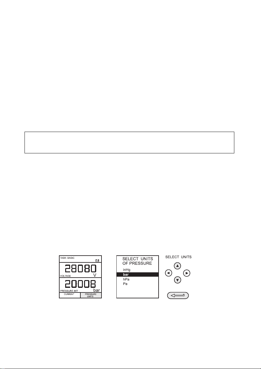
In the above diagram the following key sequence is indicated.
(a) Press the F2 key (the key immediately below the UNITS soft box).
(b) Use the Up and Down cursor keys (only) to select the required option. (If all keys
shaded, use all these keys to select or enter data).
(c) Press the ENTER key.
INTRODUCTION Summary of Functions

K0430 Issue No. 2 2
Using This Guide
The following key symbols are used in the procedure diagrams:
Shaded cursor keys indicate that a combination of these four keys, Up,
Down, Left and Right should be used to (e.g.) enter an alpha numeric
value or to select a function.
Indicates the ENTER key. Used to confirm an operation or a selection.
Shading indicates key operation.
Exit key, used to clear current menu selection and return to next menu
level above current level. Used as an escape key from current operation.
Shading indicates key operation.
Hardkey (total 7). Legend beside key symbol indicates function. Shading
indicates key operation.
Maximum Instrument Ratings
The following table shows the maximum measurement input ratings of the instrument
which should not be exceeded.
Note 1: The display flashes if the input pressure, voltage or current overrange.
Note 2: Max applied voltage for external loop supply = 30V dc (see page 8).
PRESSURE 120% FULL SCALE
VOLTAGE 30 V d.c.
CURRENT 55 mA d.c.
INTRODUCTION Summary of Functions

3 K0430 Issue No. 2
OPERATOR CONTROLS (Figure 1 and 2)
These divide into two groups, the operator/display controls (Figure 1) and the pressure/
vacuum generation components (Figure 2). The operator controls and a typical display,
common to all instrument versions, is shown below.
1 Display 2 Electrical Measurement Input Sockets 3 Cursor Keys
4 Enter Key 5 Function (soft) Keys 6 Hard Keys 7 On/Off Key
Figure 1 - DPI 610/615 IS Key-pad
DISPLAY
The display and key-pad of the instrument divides into four distinct sections. The two
main sections of the display are used to show an input and an output. The remaining
two sections show the status display area and define the soft key functions. A typical
display is shown below:
PRESSURE INT bar
VOLTAGE V
F2F1
2
3
4
5
76
1
CURRENT PRESSURE
UNITS
max 30V
TASK: BASIC
DPI 615 IS
PRESSURE INT
bar
VOLTAGE
V
CURRENT
UNITS
PRESSURE
TASK: BASIC
+
-
Input display
Output display
Soft boxes
Status display
INTRODUCTION Summary of Functions

K0430 Issue No. 2 4
HARD KEY FUNCTIONS (Fig. 1)
* These key functions are not available in BASIC mode
Key Function Page
reference
I/O
This key selects the instrument ON and OFF. 7
SETUP*
The
SETUP
key provides access to the instrument’s general
configuration parameters that are set-up to certain default
parameters on delivery.
36
ZERO
The
ZERO
key zeroes either the selected input or output display, only if
the display reading is within 5% of zero. Attempts to zero a larger
offset result in an error message,
Zero too large.
9
INPUT*
The
INPUT
key selects the input parameter to be displayed. 18, 19
TASK
The
TASK
key rapidly configures the instrument for a number of
different types of external device calibration. There are twenty task
configurations available, eleven pre-programmed configurations and
nine user defined configurations
10
OUTPUT*
The
OUTPUT
key selects the output parameter to be displayed. 24-27
STORE*
Depending upon how the instrument’s
STORE
mode is set-up, this key
is used either to store up to 20 display screens (in
SNAPSHOT
mode),
or to manually log a screen in
DATALOG
mode.
29, 36
RECALL*
This key recalls a previously stored screen to the display. Depending
on the
STORE
mode set-up, operation of this key recalls either the
snapshot of a previously stored screen or data log file. In
STORE
mode, selection displays the last screen stored. By using the cursor
keys, the operator can scroll either forward or back through memory
locations.
28, 31, 35
ENTER
The
ENTER
key either enters data (accept entered data), or, in
conjunction with the soft keys, accepts a given selection.
2
EXIT
The
EXIT
key operates in conjunction with all the other hard and soft
keys to exit from the current screen or menu level, to the level
immediately preceding it. To quit completely from any menu level,
press
EXIT
until the
MEASURE/SOURCE
screen is displayed.
2
INTRODUCTION Summary of Functions

5 K0430 Issue No. 2
SOFT KEYS (Fig. 1)
Three soft keys, designated F1, EXIT and F2, are situated immediately below the display
as shown below. These keys have their function allocated by the instrument software
which is indicated in the bottom of the display (Voltage for F1 and Units for F2 in this
example). They are used to select menu (program) options and are fully described under
the appropriate section headings.
CURSOR KEYS (Fig. 1)
The cursor keys consist of a block of four keys, designated up , down , left , and
right . In programs where options need to be selected from a list, (e.g.) the TASK
selection program, the up and down cursor keys are used to highlight one of the
options, from which it can be selected by the ENTER key. In TASK mode, where more
than one page of options are provided, the left , and right cursor keys will switch
between pages.
1 Test port, connect to unit under test 2 Hard keys
3 Cover (external interfaces) 4 Electrical inputs
5Cursorkeys 6Function(soft)keys
7 Release valve (releases pressure through 8) 8 Vent port
9 Select positive or negative pressure 10 Pump
11 Fine pressure adjuster
Figure 2 - DPI 610/615 IS Calibrator Controls
7
8
9
5
6
4
3
10
11
1
2
INTRODUCTION Summary of Functions

K0430 Issue No. 2 6
ELECTRICAL CONNECTIONS
1 Cover, closed when
not using connectors
2 External transducer
3 RS232 connector
4Temperaturesensor
Figure 3 - Electrical System Connections
Measurement inputs and Source outputs are made via the control panel sockets as
shown below:
1 Status window 2 Input window 3 Electrical measurement input sockets
4Outputwindow
Figure 4 - Electrical Measurement Inputs/Source Outputs
1
2
3
USE RS232
IN SAFE
AREA ONLY
4
PRESSURE INT
bar
VOLTAGE
V
F2F1
CURRENT
UNITS
INPUTS
OUTPUTS
4
3
12
PRESSURE
max 30V
CAT II
TASK: BASIC
DPI 615 IS
INTRODUCTION Summary of Functions
Test Equipment Depot - 800.517.8431 - 99 Washington Street Melrose, MA 02176
TestEquipmentDepot.com

7 K0430 Issue No. 2
Fitting Batteries
WARNING: BATTERIES MUST ONLY BE FITTED IN A SAFE AREA.
USE ONLY THE BATTERIES SPECIFIED IN THE TABLE.
Caution: Old batteries can leak and cause corrosion. Never leave discharged batteries in
the instrument. Old batteries should be treated as hazardous waste and
disposed of accordingly.
Switching On
Press the I/O switch on the front panel and proceed as follows:
The first time that the instrument is powered up, it will power-up in BASIC mode with the
main screen displaying voltage in the input display area and pressure in the source
display area. To switch to Current as input, press F1 as shown. Similarly, F1 to return to
Voltage.
Note: No other keys are active in this mode and the instrument can only be reconfigured
by pressing the TASK key and selecting another mode.
PRESSURE INT bar
VOLTAGE V
CURRENT
UNITS
PRESSURE
TASK: BASIC
+
-
3
2
1
Manufacturer Type No.
Energizer Industrial Type EN93
Energizer Type E93.LR14.C.AM2
Duracell Type MN1400-LR14
Varta No.4014 Type LR14.C.AM2
Procell Industrial Type MN1400-LR14
1Coverfixing
screws.
2SixalkalineC
cells, see table.
Only use the
battery type in
the table.
3 Low battery
indication.
Getting Started

K0430 Issue No. 2 8
Change Pressure Units
To change the pressure units proceed as follows. If the four units displayed are not the
units required, press TASK and select any task, other than BASIC, press SETUP and
proceed as detailed on page 36. To return to BASIC mode, press TASK and select BASIC.
In BASIC mode, the unit is configured to carry out basic Pressure to Voltage (P to V) or
Pressure to Current (P to I) tests, a typical test procedure follows:
Voltage and Current Measurements
Connect the electrical input sockets as follows for voltage and current measurements.
Use the test leads provided and DO NOT push bare wires into the sockets.
55mA
Vin
mA in
mA Sink
max 30V
max
+
-
V
55mA
Vin
mA in
mA Sink
max 30V
max
+
-
Current
Maximum input current = 55mA dc (at 30 V dc)
Voltage
Maximum applied voltage = 30V dc.
Getting Started

9 K0430 Issue No. 2
Typical Calibration Set-up (Pressure to Voltage)
Connect a device under test to the instrument as shown below:
A - External pressure source (indicator instruments only) B - Pressure regulator
C - Pressure/voltage device D - Barrier E - Excitation 10V F - Safe area
• General Procedure
Use the hand-pump to pressurize the system to the required level as indicated on
the display. Allow the display to settle and screw the volume adjuster in or out as
a fine adjustment to the required pressure. Record the input: Voltage, reading at
each applied pressure.
Zero Display Reading
Both the input and output readings can be set to zero by using the ZERO key and if the
displayed reading is within 5% of zero. To zero either the INPUT or OUTPUT displays,
proceed as follows:
P
V
+
A
B
PRESSURE INT bar
VOLTAGE
F2F1
EXIT
V
CURRENT
PRESSURE
UNITS
Max 30V
CAT II
TASK: BASIC
DPI 615 IS
CD
3
--
++
-
-
C
D
E
F
D
Getting Started

K0430 Issue No. 2 10
Task Key
The TASK key is used to set-up the instrument for a number of specific types of test.
There are two modes BASIC and ADVANCED and nine other specific types of test which
automatically configure the instrument on selection from the TASK menu. The tasks
available under the TASK menu are held on three pages shown below. To select a task
from the menu, press the TASK key, position the cursor over the required task and press
the ENTER key as shown below. Use the right/left cursor keys to switch between pages.
Using TASK Functions
Specific tasks are selected as shown above. The following diagrams show how to
connect the unit under test (UUT) for each task selectable under the TASK menu.
Input and output units, where applicable, can be selected by pressing either the INPUT or
OUTPUT keys as shown below.
Set Units
Note: If the four units displayed are not the units required, press SETUP, select SETTINGS
and refer to select regular units on page 37.
Task Selection

11 K0430 Issue No. 2
Cal Mode (DPI 615 versions only)
Cal mode, which is available in tasks P-I, P-P, P-V, P-P, P-DISPLAY and P-SWITCH, provides
a method of setting up test parameters manually. Downloaded test procedures can also
automatically set up and turn on the Cal Mode function. The method of turning on and
setting up Cal Mode is shown below for a P-I task. A similar method can be used for all
the other tasks applicable to the Cal Mode function.
Pressing the F1 key (TURN ON CAL MODE), provides the set-up screen for the CAL mode.
Initially, the cursor is placed in the UUT SPAN field to allow the required span range to be
entered. The corresponding values for the UUT output parameter (current) are then set,
followed by the maximum error value and error type (%rdg or % span). When all test
parameters have been set-up, the screen changes to display the input and output and
the test results. The test result can only be displayed to within a range of ±9.99%. If the
test result is outside this range, either the left pointing (-ve error) or right pointing (+ve
error) chevrons are displayed. Within this error band, the actual tolerance value is
displayed. Test results can either be stored as snapshots or logged as data log files,
depending on how the instrument has been set-up.
Basic Mode (Task BASIC)
This instrument will power-up in this mode the first time that it is used. To select BASIC
from any other task, press the TASK key and select BASIC and press the ENTER key.
BASIC mode is fully described in the Getting Started, section (see page 7).
0.00
2000.00
OUTPUT
MAX. ERROR
ERROR TYPE
CHANGE
VALUE
psi
=
=
=
=
=
mA
4.00
20.00
LINEAR
0.05%
%span
PI SELECT VALUE
psi
mA
TASK : P-I
DATALOG
24V OFF
..........
. %span FAIL
TURN OFF
CAL MODE
TURN ON
CAL MODE
mA
TASK : P-I
DATALOG
24V OFF
..........
psi
Task Selection
Other manuals for Druck DPI 610
2
This manual suits for next models
1
Table of contents
Other GE Test Equipment manuals

GE
GE ADTS542F User manual

GE
GE MicroVersaTrip TVTS1 User manual

GE
GE DMS Go+ User manual

GE
GE PACE5000 Use and care manual

GE
GE Druck DPI 841 User manual

GE
GE Druck DPI611 User manual

GE
GE Multilin EPM 7000 User manual

GE
GE Druck ADTS 405 R Mk2 User manual

GE
GE EVT-Pro User manual

GE
GE Druck ADTS 405 R/F Mk2 User manual