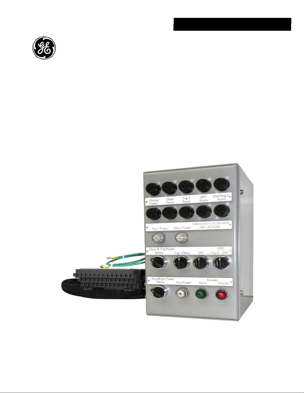
EntelliGuard GTM Breaker Test Cabinet
Section 1. Introduction
1-1 Introduction
This manual provides the information needed by the user
to properly install, operate and maintain the Test Cabinet.
1-2 Safety
Each user must maintain a safety program for the
protection of personnel, as well as other equipment, from
the potential hazards associated with electrical
equipment.
The following requirements are intended to augment the
user’s safety program, but NOT supplant the user’s
responsibility for devising a complete safety program.
The following basic industry practiced safety
requirements are applicable to all major electrical
equipment such as switchgear or switchboards. GE
neither condones nor assumes any responsibility for
practices which deviate from the following:
1. ALL CONDUCTORS MUST BE ASSUMED TO BE
ENERGIZED UNLESS THEIR POTENTIAL HAS BEEN
MEASURED AS GROUND AND SUITABLE GROUNDING
CONDUCTORS HAVE BEEN APPLIED TO PREVENT
ENERGIZING. Many accidents have been caused by
back feeds from a wide variety of sources.
2. Although interlocks to reduce some of the risks are
provided, the individual’s actions while performing
service or maintenance are essential to prevent
accidents. Each person’s knowledge; his mental
awareness; and his planned and executed actions
often determine if an accident will occur. The most
important method of avoiding accidents is for all
associated personnel to carefully apply a thorough
under-standing of the specific equipment from the
viewpoints of its purpose, its construction, its
operation and the situations that could be
hazardous.
All personnel associated with installation, operation and
maintenance of electrical equipment, such as power
circuit breakers and other power handling equipment,
must be thoroughly instructed, with periodic retraining,
regarding power equipment in general as well as the
particular model of equipment with which they are
working. Instruction books, actual devices and
appropriate safety and maintenance practices such as
OSHA publications, National Electric Safety Code (ANSI
C2), the National Electric Code, and National Fire
Protection Association (NFPA) 70B Electrical Equipment
Maintenance must be closely studied and followed.
During actual work, supervision should audit practices to
assure conformance.
1-3 Maintenance
Excellent maintenance is essential for reliability and
safety of any electrical equipment. Maintenance
programs must be tuned to the specific application, well
planned and carried out consistent with both industry
experience and manufacturer’s recommendations. Local
environment must always be considered in such
programs, including such variables as ambient
temperatures, extreme moisture, number of operations,
corrosive atmosphere or major insect problems and any
other unusual or abusive condition of the application.
One of the critical service activities, sometimes neglected,
involves the calibration of various control devices. These
monitor conditions in the primary and secondary circuits,
sometimes initiating emergency corrective action such
as opening or closing circuit breakers. In view of the vital
role of these devices, it is important that a periodic test
program be followed. As was outlined above, it is
recognized that the interval between periodic checks will
vary depending upon environment, the type of device
and the user’s experience. It is the GE recommendation
that, until the user has accumulated enough experience
to select a test interval better suited to his individual
requirements, all significant calibrations be checked at an
interval of one to two years.
To accomplish this, some devices can be adequately
tested using test sets. Specific calibration instructions on
particular devices typically are provided by supplied
instruction books.
Instruction books supplied by manufacturers address
components that would normally require service or
maintenance during the useful life of the equipment.
However, they cannot include every possible part that
could require attention, particularly over a very long
service period or under adverse environments.
Maintenance personnel must be alert to deterioration of
any part of the supplied switchgear, taking actions, as
necessary to restore it to serviceable status.
Industry publications of recommended maintenance
practices such as ANSI/NFPA 70B, Electrical Equipment
Maintenance, should be carefully studied and applied in
each user’s formation of planned maintenance.
4